Table of Contents
Advertisement
Quick Links
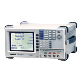
Precision LCR Meter
LCR-8000G Series
USER MANUAL
GW INSTEK PART NO. 82CR-81010MD1
ISO-9001 CERTIFIED MANUFACTURER
This manual contains proprietary information, which is protected by
copyright. All rights are reserved. No part of this manual may be
photocopied, reproduced or translated to another language without
prior written consent of Good Will company.
The information in this manual was correct at the time of printing.
However, Good Will continues to improve products and reserves the
right to change specification, equipment, and maintenance
procedures at any time without notice.
Good Will Instrument Co., Ltd.
No. 7-1, Jhongsing Rd., Tucheng City, Taipei County 236, Taiwan. . . .
Advertisement
Chapters
Table of Contents

Related Manuals for GW Instek LCR-8101G


Summary of Contents for GW Instek LCR-8101G
- Page 1 Precision LCR Meter LCR-8000G Series USER MANUAL GW INSTEK PART NO. 82CR-81010MD1 This manual contains proprietary information, which is protected by copyright. All rights are reserved. No part of this manual may be photocopied, reproduced or translated to another language without prior written consent of Good Will company.
-
Page 2: Table Of Contents
TABLE OF CONTENTS LCR-8000G Series User Manual Speed / Step Setting ......101 Running Graph Measurement .... 103 Table of Contents R R R R EMOTE CONTROL EMOTE CONTROL ........ EMOTE CONTROL EMOTE CONTROL ......................................107 S S S S AFETY INSTRUCTION AFETY INSTRUCTION... - Page 3 TABLE OF CONTENTS LCR-8000G Series User Manual Do not dispose electronic equipment as unsorted municipal waste. Please use a separate collection facility or contact the supplier from which this instrument was purchased. AFETY INSTRUCTION Safety Guidelines This chapter contains important safety instructions that you must follow when operating General Do not place any heavy object on the...
- Page 4 SAFETY INSTRUCTION LCR-8000G Series User Manual (Pollution Degree) EN 61010-1:2001 specifies the pollution degrees Fuse Fuse type: T3A/250V and their requirements as follows. The LCR-8000G falls under • degree 2. Make sure the correct type of fuse is installed • Pollution refers to “addition of foreign matter, solid, liquid, or before power up.
-
Page 5: Etting Started
SAFETY INSTRUCTION LCR-8000G Series User Manual Power cord for the United Kingdom When using an LCR-8000G series LCR meter in the United Kingdom, make sure the power cord meets the following safety instructions. ETTING STARTED NOTE: This lead/appliance must only be wired by competent persons WARNING: THIS APPLIANCE MUST BE EARTHED This chapter describes the LCR-8000G series in a IMPORTANT: The wires in this lead are coloured in accordance with the... -
Page 6: Main Features
GETTING STARTED LCR-8000G Series User Manual Fixture Fixture structure............24 Main Features connection Fixture connection ............25 Tutorial Basic measurement (without Pass/Fail test) .....26 Performance 20Hz ~ 10MHz wide test frequency (LCR- • Pass/Fail test (Single step) .........28 8110G) Pass/Fail test (Multiple step)........30 6 digit measurement resolution •... -
Page 7: Package Contents
Ensure all the package contents are included and defect-free before 1st measurement 2nd measurement Circuit model Graph *Prog using the LCR-8000G. If any of the contents in your package are missing or damaged, please contact your nearest GW Instek G Angle Series Parallel distributor. Capacitance (C) Inductance (L) -
Page 8: Model Comparison
Model Comparison Single/ Main Function Local Menu Calibration Unit Trigger Repetitive Display Keys Keys Major Model Differences Arrow Keys Model LCR-8101G LCR-8105G LCR-8110G Menu D / Q Trig V / A Local Code Measurement 20Hz~1MHz 20Hz~5MHz 20Hz~10MHz ∝ Ω Frequency Clear... - Page 9 GETTING STARTED LCR-8000G Series User Manual Calibration key Enters the calibration mode. See Enter key Confirms the entered value or Enter Calibration page123 for calibration details. selection. Unit keys Enters unit when editing values. Numerical keys Enters numeric values. Dissipation factor or Quality factor Voltage or Ampere Henry (for Inductance) Measurement...
-
Page 10: Rear Panel Overview
GETTING STARTED LCR-8000G Series User Manual Voltage selector / The voltage selector sets the AC Rear Panel Overview Fuse holder / mains voltage: Display Mains socket AC 115V (+10% / -25%), AC 230V Contrast GPIB RS-232C Voltage Fuse Mains (+15% / -14%) (Selectable), Knob Port Port... -
Page 11: Tilt Stand & Power Up
GETTING STARTED LCR-8000G Series User Manual Tilt Stand & Power Up Power up Tilt stand 1. Set the rear panel 230V 115V Voltage selector to the Low angle Panel operation correct position according to the AC mains voltage. 2. Connect the power cord to the socket. -
Page 12: Fixture Connection
GETTING STARTED LCR-8000G Series User Manual Fixture Connection Select AC mains frequency (50/60Hz) Fixture structure Background Although the LCR-8000G works under both 50 and 60Hz power frequencies, we recommend selecting the frequency that matches the local setting to get Background The standard fixture is a four-wire type with a the best measurement precision, especially at common terminal for screen connection. -
Page 13: Tutorials (Step By Step Operations)
GETTING STARTED LCR-8000G Series User Manual Tutorials (Step by Step Operations) Fixture connection Basic measurement (without Pass/Fail test) Panel operation 1. Discharge the test component before connecting the fixture set. Step Description Details 2. Connect each fixture terminal to the front panel 1. - Page 14 GETTING STARTED LCR-8000G Series User Manual Optional settings To hide the drive Voltage/Current, press Page57 the Code key, type 80, then press Enter. Pass/Fail test (Single step) Page51 Set the Range (internal setting) to Auto, Step Description Details use the Left/Right key to move the cursor and Up/Down key to change the setting.
- Page 15 GETTING STARTED LCR-8000G Series User Manual 10b. Select Press the Sing/Rep key to select Page56 Repetitive Repetitive (automatic trigger) Pass/Fail test (Multiple step) measurement measurement. Press the Left/Right arrow key and move the cursor to Speed. Press Step Description Details the Up/Down key to select the speed.
- Page 16 GETTING STARTED LCR-8000G Series User Manual 8. Enter Run Press F6 (Run). The Run menu opens. Page80 menu Graph mode 9. Set Single or Press the Sing/Rep key to select Single Page80 Repetitive (manual trigger) or Repetitive (auto Step Description Details trigger).
-
Page 17: Measurement Tip
GETTING STARTED LCR-8000G Series User Manual 8b. Set vertical Press F2 (Abs/%) to select Abs, then press Page94 Measurement tip scale (Absolute + F3 (Manual/Auto fit) to select Manual fit. Manual fit) Move the cursor to Hi, set the Hi value. Repeat this for Lo as well. - Page 18 GETTING STARTED LCR-8000G Series User Manual Wire capacitance When measuring the wire capacitance, the fixture clips that are marked with H (High Force)/H (High Sense) should always be connected to the point that is influenced the most by noise. ASIC MEASUREMENT Wire inductance The wire inductance should be subtracted from the measurement result.
-
Page 19: Measurement Item Description
BASIC MEASUREMENT LCR-8000G Series User Manual Measurement Item Description Series/Parallel circuit models In general, two items, primary and secondary, are combined in a single measurement. The following table shows the available Background For measuring AC Resistance, Capacitance, combinations. Overview of each measurement item is listed from Reactance, Inductance, and Susceptance, series and the next page. -
Page 20: Resistance (R) And Conductance (G = 1/R)
BASIC MEASUREMENT LCR-8000G Series User Manual Series formula Parallel formula Resistance (R) and Conductance (G = 1/R) Background Resistance measures how difficult it is for the ... -
Page 21: Capacitance (C)
BASIC MEASUREMENT LCR-8000G Series User Manual Capacitance (C) Inductance (L) Background Capacitance measures the amount of electronic Background Inductance measures the amount of magnetic flux charge stored between two terminals. generated in certain electrical current. Display Range 0.001pF ~ 1F Display Range 0.1nH ~ 100kH Type... -
Page 22: Reactance (X) And Susceptance (B = 1/X)
BASIC MEASUREMENT LCR-8000G Series User Manual Reactance (X) and Susceptance (B = 1/X) Impedance (Z) and Admittance (Y = 1/Z) Background Reactance measures the imaginary part of Background Impedance measures the total amount of Impedance (Z) caused by capacitors or inductors. opposition between two terminals in an AC circuit. -
Page 23: Quality Factor (Q) And Dissipation Factor (D)
BASIC MEASUREMENT LCR-8000G Series User Manual Quality factor (Q) and Dissipation factor (D) Angle (θ) Background Both Quality factor and its reciprocal, Dissipation Background The Angle (θ) measures the phase on which factor, are used for measuring the rate of energy Impedance (Z), Admittance (Y), Quality factor (Q), dissipation relative to the measurement frequency. -
Page 24: Measurement Mode Overview
BASIC MEASUREMENT LCR-8000G Series User Manual Measurement Mode Overview Display overview Normal mode Enter measurement mode Type C, L, X, B, Z, Y, Q, D, R, G, θ Menu Panel operation 1. Press the Menu key. The main menu appears. MAIN MENU AC MEAS Rdc MEAS... -
Page 25: Parameter Configuration
BASIC MEASUREMENT LCR-8000G Series User Manual Delta mode (Pass/Fail test) Parameter Configuration Select measurement item *This is not necessary for Rdc measurement. Measurement The following list shows the available combination combination of the first and second measurement items. Capacitance (C) Series C-Q, C-D, C-R Parallel C-Q, C-D, C-R, C-G... -
Page 26: Set Measurement Range To Auto
– 0.2179 2. Enter the frequency using the numerical keys. Panel operation 1. Press the Left/Right key Range 20Hz ~ 1MHz (LCR-8101G) repeatedly to move the cursor to 20Hz ~5MHz (LCR-8105G) Range position. 20Hz ~10MHz (LCR-8110G) Range Auto Speed Slow 1.2kHz... -
Page 27: Set Measurement Voltage
BASIC MEASUREMENT LCR-8000G Series User Manual Select frequency For frequency increase/decrease using Up/Down Set measurement voltage step resolution keys, fine and coarse step settings are available. Fine digit: 1, 2, 3, 4, 5, 6... Background The measurement voltage, together with the Coarse digit: 10, 12, 15, 20, 25, 30, 40, 50, 60, 80 measurement frequency, defines the electrical... -
Page 28: Running Measurement
BASIC MEASUREMENT LCR-8000G Series User Manual Running Measurement Select Repetitive measurement Select Single measurement Background The data capture can be manually controlled (Single) or automatically updated (Repetitive). In single measurement, the measurement is Background The data capture can be manually controlled activated by pressing the Trigger key. -
Page 29: Ass
BASIC MEASUREMENT LCR-8000G Series User Manual AC≤ AC≤ AC> AC≥ 100Hz 2kHz 2kHz 1MHz Slow 900ms 1.3s 600ms 600ms 620ms 120ms 1.2s 470ms 450ms 470ms ASS-FAIL MODE Fast 60ms 650ms 180ms 150ms 150ms 30ms 600ms 120ms 75ms 120ms In the Pass/Fail test mode, measurement results are compared with user-defined limits and the results Beep setting If the beep setting (page61) is active and... -
Page 30: Single-Step Test Configuration
PASS-FAIL MODE LCR-8000G Series User Manual Overview ..............70 Multi-step Single-Step Test Configuration configuration Configure beep setting ..........72 Configure the Average ..........73 Overview Enter multi-step mode..........74 Create new program ............74 Background / test Pass/Fail test checks whether the measurement Edit program step ............76 type result sits between the Hi(high) and Lo(low) limit. -
Page 31: Configure The Average
PASS-FAIL MODE LCR-8000G Series User Manual Parallel resistance θ Angle Beep in repetitive If the repetitive measurement is On, the beep For detailed description of each item, see page37. mode might sound continuously. If this becomes a problem, either use the Single mode (press Sing/Rep key) or turn Off the beep. - Page 32 PASS-FAIL MODE LCR-8000G Series User Manual Select test item and scale (Pass/Fail test) Set parameters For more detailed descriptions, see Basic measurement, page47. Test item To select the first measurement item, How to edit Example press F1 repeatedly. Enter 100mV L X B Z Y Backspace All clear...
-
Page 33: Single-Step Test Run
PASS-FAIL MODE LCR-8000G Series User Manual Frequency (except Press the Left/Right key repeatedly to Single-Step Test Run Rdc) move the cursor to Frequency, and use the numerical and unit keys to enter the value. Run in Absolute mode 2.00 195.00 kHz 1. - Page 34 PASS-FAIL MODE LCR-8000G Series User Manual Result > Hi Hi and Lo values are automatically swapped if necessary Hi and Lo Swapped Result < Lo 4. The display updates the Hi/Lo result Lo < Result < Hi PASS immediately. The result is pass if the bar stays (Pass) in the central area.
-
Page 35: Multi-Step Test Configuration
PASS-FAIL MODE LCR-8000G Series User Manual Backspace All clear Multi-Step Test Configuration Clear Hi and Lo values are automatically swapped if Overview necessary Hi and Lo Swapped Background The multi-step function can configure and run multiple measurement steps. Maximum 64 programs, 30 steps each, can be programmed and 4. - Page 36 (1mV step) 10mV ~ 1V (AC>3 MHz) Background The beep sounds when the pass/fail test result Frequency 20Hz ~ 1MHz (LCR-8101G) matches the setting: failed or passed. 20Hz ~ 5MHz (LCR-8105G) 20Hz ~ 10MHz (LCR-8110G) Panel operation 1. Press the Menu key, then F5...
-
Page 37: Enter Multi-Step Mode
PASS-FAIL MODE LCR-8000G Series User Manual Configure the Average Enter multi-step mode Background The Average function sets the number of samples Panel operation Press the Menu key, then F3 (Multi Menu used, which are then averaged as the final output. Step). -
Page 38: Edit Program Step
PASS-FAIL MODE LCR-8000G Series User Manual Move cursor JKLMNOPQRS (Left/Right keys) Edit program step Enter the letter program name: N_ How to edit For selecting parameters, press F1 • (Down key) parameter (Prog) repeatedly. For entering values, use the numerical and unit •... - Page 39 PASS-FAIL MODE LCR-8000G Series User Manual Set frequency Set Hi limit Move the cursor to Freq column. Move the cursor to Hi column. Func Enter the frequency using the Enter the Hi limit using the Freq 500.00 1.0000H numerical keys and unit keys. numerical keys and unit keys.
-
Page 40: Multi-Step Program Run
PASS-FAIL MODE LCR-8000G Series User Manual Multi-Step Program Run Copy (duplicate) program step Background Copying the step inserts a new, identical step next Run program to the current step (= the step where the cursor resides). Panel operation 1. When editing is completed, press F6 Panel operation Press F2 (Copy). - Page 41 PASS-FAIL MODE LCR-8000G Series User Manual The rightmost row shows the result for each 3. In Manual (single) mode press F1 Trig step. (Start) or the Trigger key to Failed: below the Lo limit manually start the program. The test results show up according to the Failed: above the Hi limit program contents.
-
Page 42: Multi-Step Program File Operation
PASS-FAIL MODE LCR-8000G Series User Manual 3. Press the Enter key to confirm the Multi-Step Program File Operation Enter file name. To quit the Save as mode, press the Clear key. Clear Save program 4. The display goes back to the previous mode, Save (overwrite) with the program changed to the new name. -
Page 43: Recall (Load) Existing Program
PASS-FAIL MODE LCR-8000G Series User Manual Recall (load) existing program Delete existing program Panel operation 1. Press F5 (File). The file menu Recall program 1. Press F5 (File), then F2 (Delete). The appears. existing programs appear, listed in alphabetical order. 2. -
Page 44: Raph Mode
GRAPH MODE LCR-8000G Series User Manual Item Selection Enter graph mode RAPH MODE Panel operation 1. Press the Menu key. The main menu Menu appears. The graph function shows the component characteristics in visual manner. Voltage and Frequency sweep are selectable for the horizontal MAIN MENU scale. -
Page 45: Horizontal Scale Setting
GRAPH MODE LCR-8000G Series User Manual Horizontal Scale Setting Select measurement item Range Series inductance θ Angle Set horizontal axis (Voltage) Parallel inductance Rs Series resistance Background The X (horizontal) axis is selectable from Voltage Quality factor Parallel resistance and Frequency sweep. Series capacitance Reactance When Voltage sweep is selected: measurement... -
Page 46: Set Horizontal Axis (Frequency)
GRAPH MODE LCR-8000G Series User Manual Unit Mismatched Set horizontal axis (Frequency) If a value outside of the range is entered, the closest available value is automatically selected. Background The X (horizontal) axis is selectable from Voltage and Frequency sweep. Nearest Available When Voltage sweep is selected: measurement •... -
Page 47: Vertical Scale Setting
GRAPH MODE LCR-8000G Series User Manual Unit Mismatched Vertical Scale Setting If a value outside of the range is entered, the closest available value is automatically selected. Set vertical axis (Manual + Absolute) Nearest Available Background The Y (vertical) axis configuration is available for: If the entered start Frequency is higher than the Manual or Automatic fit: Selects whether the •... -
Page 48: Set Vertical Axis (Manual + Percentage)
GRAPH MODE LCR-8000G Series User Manual Backspace All clear Clear Set vertical axis (Manual + Percentage) If a wrong unit is entered, the value is cancelled. Background The Y (vertical) axis configuration is available for: Manual or Automatic fit: Selects whether the Unit Mismatched •... -
Page 49: Set Vertical Axis (Auto + Absolute)
GRAPH MODE LCR-8000G Series User Manual Set vertical axis (Auto + Absolute) If a wrong unit is entered, the value is cancelled. Background The Y (vertical) axis configuration is available for: Unit Mismatched Manual or Automatic fit: Selects whether the •... -
Page 50: Set Vertical Axis (Auto + Percentage)
GRAPH MODE LCR-8000G Series User Manual Backspace All clear Clear Set vertical axis (Auto + Percentage) Background The Y (vertical) axis configuration is available for: If a wrong unit is entered, the value is cancelled. Manual or Automatic fit: Selects whether the •... -
Page 51: Speed / Step Setting
GRAPH MODE LCR-8000G Series User Manual Select step size Speed / Step Setting Background The step size selects whether to plot every captured data (step size 1) or to plot only the selected data (step size 2, 4, 8 = every 2, 4, 8 data). Select measurement speed (capture timing) Step size 1: detailed graph, slow capturing Background... -
Page 52: Running Graph Measurement
GRAPH MODE LCR-8000G Series User Manual Marker Running Graph Measurement CAPACITANCE VS FREQUENCY FUNCTION Run measurement 300.0n Panel operation 1. When the configuration is 250.0n completed, press F4 (Start) to start the graph measurement. (Hz) 20.0 40.0 60.0 80.0 2. The display changes into graph mode and starts MKR: 32.000 Hz LEVEL: 10.0mV RETURN... - Page 53 GRAPH MODE LCR-8000G Series User Manual Adjust vertical scale Observe Graph Data Background When the measured data does not fit into the Background When the graph is completed (page103) and the original vertical scale, use this function so that the vertical scale is adjusted (page105), use the marker LCR-8000G automatically adjusts the scale to to observe the measurement data in detail.
-
Page 54: Emote Control
6 7 8 9 7: RTS (Request to send) 8: CTS (Clear to send) 1, 4, 6, 9: No connection PC connection Use the Null Modem connection as in the below diagram. LCR-8101G Pin2 Pin2 Pin3 Pin3 Pin5 Pin5 Pin7... - Page 55 REMOTE CONTROL LCR-8000G Series User Manual Select GPIB 1. Press the Menu key and F5 (System). Menu Configure GPIB interface address The system configuration appears. Connection Connect the GPIB cable to the rear panel port: 24-pin female connector. Pin assignment Pin1 Pin13 Data line 5 Data line 1...
-
Page 56: Command Syntax
*idn? Returns the LCR identification: Manufacturer, Model No, Serial No, Firmware version. <NR1> integers 0, 1, 2, 3 Example: GW INSTEK, 8101, 0, 2.04 <NR2> decimal numbers 0.1, 3.14, 8.5 *loc Sets the instrument to local state. <NR3> floating point 4.5e-1, 8.25e+1... - Page 57 REMOTE CONTROL LCR-8000G Series User Manual *stb? Returns the current contents of the Status Byte :meas:func:minor Returns the second AC function. with the Master Summary bits as an integer in the Parameter: 0 (Q), 1 (D), 2 (R), 3 (G) range 0 to 255.
- Page 58 REMOTE CONTROL LCR-8000G Series User Manual :meas:speed Selects or returns measurement speed. :multi:delay Sets or returns trigger delay time for currently <disc> <NR2> selected step in millisecond. Send parameter: max, fast, med, slow :meas:speed? :multi:delay? Parameter: 0ms ~ 1000ms Return parameter: 0 (max), 1 (fast), 2 (med), 3 (slow) Example: :multi:delay 10m (10ms) :meas:test:ac...
- Page 59 REMOTE CONTROL LCR-8000G Series User Manual Graph command :multi:new Create a new multi-step program. <filename> Example: :multi:new demo (file name demo) :graph Select graphing mode / path. :multi:res? Query the results of the test for each step. Set the measurement function for the graph mode. : graph:func Parameter: 0 (Pass), 1 (Fail Hi), 2 (Fail Lo) Parameter: ls lp q cs cp d z phase rs rp x g b y rdc...
- Page 60 REMOTE CONTROL LCR-8000G Series User Manual Returns the frequency if the sweep mode is drive Set the minimum value for Y-axis in the graph :graph:freq? level mode. Parameter: real number up to 1^12 (1e+12) Set the drive level if the sweep mode is frequency. :graph:lo-lim <NR3>...
- Page 61 REMOTE CONTROL LCR-8000G Series User Manual Returns the measurement from the current marker Move the marker to the highest point on the position. current graph. :graph:peak Returned parameter: Depending on the measured Example: :graph:peak :graph:mk? parameters. Move the marker to the lowest point on the current Example: (Series inductance) -3.510606e-03 (mH) graph.
- Page 62 CALIBRATION LCR-8000G Series User Manual Alternative S/C An alternative method of S/C trimming. trimming ALIBRATION Overview Background Calibration (trimming) eliminates stray capacitance and series impedance from the testing fixture. It is required when using the instrument in a new environment, or using a new set of testing fixtures.
- Page 63 Frequency range is 0Hz ~ 10kHz. CALIBRATE MODE O/C Trim <= 100kHz Frequency range is 0Hz ~ 100kHz. All freq S/C Trim 0Hz~=<1MHz (LCR-8101G) 0Hz~=<5MHz (LCR-8105G) 0Hz~=<10MHz (LCR-8110G) Frequency limit example: When using a special MEASURE fixture set, trimming failed at 50kHz which is...
- Page 64 CALIBRATION LCR-8000G Series User Manual using to calculate a measurement. However, this 5. The trimming starts and ends automatically. measurement is only an approximation. To obtain the most optimized measurement accuracy and to clear the warning message, it is best to perform O/S trimming again, based on the actual measuring ALL FREQUENCY SHORT CIRCUIT TRIM...
-
Page 65: Ppendix
LCR-8000G Series User Manual PPENDIX Q1. The beep keeps sounding. Fuse Replacement A1. The beep sounds according to the pass/fail test result, which in this case is set to repetitive mode. Do one of the following. Step 1. Take off the power cord and remove the fuse socket using a minus driver. -
Page 66: O/S Trimming Points
An “O/S Trim Error!” warning should not appear after running an The frequency of the extra trimming point is the measurement all frequency O/S trimming. frequency you were using before entering the calibration mode. Model LCR-8101G LCR-8105G LCR-8110G Trimming Point 13 points... -
Page 67: Z| Accuracy Chart
≦ kHz trimming if you choose to use a measuring frequency higher than 10 kHz or other than where you were when you ran the ≦ kHz trimming. LCR Models LCR-8101G LCR-8105G LCR-8110G Trimming Point 7 points 7 points 7 points... - Page 68 APPENDIX LCR-8000G Series User Manual |Z| vs L, C Chart Accuracy Definition |Z|, |Y| High Impedance Ae[%]=±((A+0.0000001*Zx)*Kv*Kt) Low Impedance Ae[%]=±((A+0.1/Zx)*Kv*Kt) L, C, X, B High Impedance when D < 0.1 Ae[%] = ± (( A + 0.0000001*Zx ) * Kv * Kt) High Impedance when D ≥...
- Page 69 APPENDIX LCR-8000G Series User Manual AC≥1~10MHz Max:120ms; Fast:150ms; (LCR-8110G) Medium:470ms; Slow:620ms Specification Test Frequency LCR-8101G DC, AC:20Hz~1MHz LCR-8105G DC, AC:20Hz~5MHz Drive Signal Level LCR-8101G DC:0.01V~2V LCR-8110G DC, AC:20Hz~10MHz AC: 20Hz~1MHz: 0.01V~2Vrms Basic Accuracy R,Z,X,G,Y,B,L,C ±0.1%@1kHz LCR-8105G DC:0.01V~2V R&G Accuracy AC 20Hz~≤3MHz:0.01V~2Vrms AC >3MHz~5MHz:0.01V~1Vrms...
- Page 70 APPENDIX LCR-8000G Series User Manual AC Drive Signal 5 Digits, Frequency ±0.005% Accuracy LCD Display 320×240 Dot Matrix Interface RS-232, GPIB GPIB Address 0~30 inclusive Dimensions 330 (W) × 170 (H) × 340 (D), Unit: mm Weight Approx. 5kg Power Source AC 115V (+10% / -25%), AC 230V (+15% / -14%) (Selectable), 50/60Hz.
-
Page 71: Accuracy Definition
66 display faq ......... 129 accessories ....... 13 Type of Product: High Precision LCR Meter Model Number: LCR-8101G; LCR-8105G; LCR-8110G accuracy overview ........ 48 are herewith confirmed to comply with the requirements set out in the dissipation factor specification ...... -
Page 72: Specification
INDEX LCR-8000G Series User Manual graph mode......87 power supply speed setting trimming ........125 configuration......88 frequency selection ....23 graph mode......101 UK power cord......9 run .........103 socket overview..... 20 step size setting, graph mode unit keys overview ....17 tutorial ........32 power up sequence ....
Need help?
Do you have a question about the LCR-8101G and is the answer not in the manual?
Questions and answers