Table of Contents
Advertisement
Quick Links
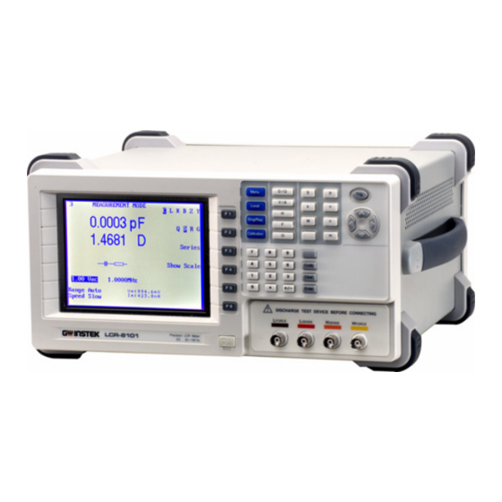
Precision LCR Meter
LCR-8101
USER MANUAL
GW INSTEK PART NO. 82CR-81010M01
ISO-9001 CERTIFIED MANUFACTURER
This manual contains proprietary information, which is protected by
copyrights. All rights are reserved. No part of this manual may be
photocopied, reproduced or translated to another language without
prior written consent of Good Will company.
The information in this manual was correct at the time of printing.
However, Good Will continues to improve products and reserves the
rights to change specification, equipment, and maintenance
procedures at any time without notice.
Good Will Instrument Co., Ltd.
No. 7-1, Jhongsing Rd., Tucheng City, Taipei County 236, Taiwan.
Advertisement
Chapters
Table of Contents

Related Manuals for GW Instek LCR-8101


Summary of Contents for GW Instek LCR-8101
- Page 1 Precision LCR Meter LCR-8101 USER MANUAL GW INSTEK PART NO. 82CR-81010M01 This manual contains proprietary information, which is protected by copyrights. All rights are reserved. No part of this manual may be photocopied, reproduced or translated to another language without prior written consent of Good Will company.
-
Page 2: Table Of Contents
TABLE OF CONTENTS LCR-8101 User Manual REMOTE CONTROL ............94 Table of Contents Interface Configuration ......95 Command Syntax ......... 98 Command Set ........99 SAFETY INSTRUCTION ............. 5 CALIBRATION ..............105 GETTING STARTED ............9 Main Features ........10 FAQ ................109 Measurement Type ....... -
Page 3: Safety Instruction
Do not disassemble LCR-8101 unless you are • Safety Symbols qualified as service personnel. These safety symbols may appear in this manual or on LCR-8101. (Measurement categories) EN 61010-1:2001 specifies the measurement categories and their requirements as follows. LCR- 8101 falls under category I. - Page 4 Make sure the cause of fuse blowout is fixed • Power cord for the United Kingdom before fuse replacement. When using LCR-8101 in the United Kingdom, make sure the power Disconnect the power cord before cleaning. Cleaning LCR- • cord meets the following safety instructions.
-
Page 5: Getting Started
ETTING STARTED 6 digit measurement resolution • 10mV ~ 2V measurement drive level • This chapter describes LCR-8101 in a nutshell, 0.1% basic measurement accuracy • including its main features, front / rear panel appearance, and power up sequence. Use the... -
Page 6: Measurement Type
GETTING STARTED LCR-8101 User Manual Measurement Type Front Panel Overview Single/ Measurement item Main Function Local Menu Calibration Unit Trigger Repetitive Display Keys Keys Arrow Capacitance (C) Inductance (L) Primary Keys measurement D / Q Menu Trig Reactance (X) Susceptance (B) (=1/X) - Page 7 GETTING STARTED LCR-8101 User Manual Calibration key Enters the calibration mode. See Enter key Confirms the entered value or Enter Calibration page105 for calibration details. selection. Enters unit when editing values. Enters numeric values. Unit keys Numerical keys Dissipation factor or Quality factor...
-
Page 8: Rear Panel Overview
GETTING STARTED LCR-8101 User Manual Rear Panel Overview Tilt Stand & Power Up Display Contrast GPIB RS-232C Voltage Fuse Mains Tilt stand Knob Port Port Selector Holder Socket Low angle RS232 GPIB AC 115 / 230V 50 / 60Hz FUSE 250V T 3A WARNING SER.NO. -
Page 9: Select Ac Mains Frequency (50/60Hz)
Panel operation 1. Set the rear panel 115V 230V Background Although LCR-8101 works under both 50 and Voltage selector to the 60Hz power frequencies, we recommend selecting correct position the frequency that matches the local setting to get according to the AC the best measurement precision, especially at mains voltage. -
Page 10: Fixture Connection
GETTING STARTED LCR-8101 User Manual Fixture Connection Fixture connection Fixture structure Panel operation 1. Discharge the test component before connecting the fixture set. The standard fixture is a four-wire type with a Background 2. Connect each fixture terminal to the front panel common terminal for screen connection. -
Page 11: Tutorials (Step By Step Operations)
GETTING STARTED LCR-8101 User Manual Tutorials (Step by Step Operations) Pass/Fail test (Single step) Step Description Details Basic measurement (without Pass/Fail test) 1. Connect fixture Connect the fixture to the DUT. Page19 Step Description Details 2. Set buzzer Press the Menu key, then F5 (System). -
Page 12: Pass/Fail Test (Multiple Step)
GETTING STARTED LCR-8101 User Manual Press F5 (Abs/%) to select Abs. Press the Page58 9a. Select Absolute Left/Right key to move the cursor to Lo Pass/Fail test (Multiple step) measurement (Low limit). Use the numerical and unit keys to set the Low limit. Repeat this for... -
Page 13: Graph Mode
Page78 7. Select linear or log scale logarithmic horizontal scale. Press F2 (Abs/%) to select Abs, then press Page86 8a. Set vertical scale (Absolute + F3 (Manual/Auto fit) to select Auto fit. Auto fit) LCR-8101 automatically configures the vertical scale. -
Page 14: Measurement Tip
S/C trim at the measurement frequency (Spot (Peak). To move to the dip, press F4 (Dip). trimming). LCR-8101 measures the difference Press F1 (View) to go back. between the inductance of S/C trimming and the inductance of test component. Four-terminal... - Page 15 GETTING STARTED LCR-8101 User Manual When an inductor is measured at a frequency Frequency factor in inductor much lower than that for which it is designed (for measurement example, an HF choke tested at AF), the inductor tends to behave as an inductive resistor. In these...
-
Page 16: Basic Measurement
BASIC MEASUREMENT LCR-8101 User Manual Measurement Item Description Series/Parallel circuit models In general, two items, primary and secondary, are combined in a single measurement. The following table shows the available Background For measuring AC Resistance, Capacitance, combinations. Overview of each measurement items is listed from Reactance, Inductance, and Susceptance, series and the next page. -
Page 17: Resistance (R) And Conductance (G = 1/R)
BASIC MEASUREMENT LCR-8101 User Manual Series formula Parallel formula Resistance (R) and Conductance (G = 1/R) ⎛ ⎞ ⎜ ⎜ ⎟ ⎟ ⎛ ⎞ ⎝ ⎠ ⎜ ⎜ ⎟ ⎟ Background Resistance measures how difficult it is for the ⎝... -
Page 18: Capacitance (C)
BASIC MEASUREMENT LCR-8101 User Manual Capacitance (C) Inductance (L) Background Capacitance measures the amount of electronic Background Inductance measures the amount of magnetic flux charge stored between two terminals. generated in certain electrical current. 0.001pF ~ 1F 0.1nH ~ 100kH... -
Page 19: Reactance (X) And Susceptance (B = 1/X)
BASIC MEASUREMENT LCR-8101 User Manual Reactance (X) and Susceptance (B = 1/X) Impedance (Z) and Admittance (Y = 1/Z) Background Reactance measures the imaginary part of Background Impedance measures the total amount of Impedance (Z) caused by capacitors or inductors. -
Page 20: Quality Factor (Q) And Dissipation Factor (D)
BASIC MEASUREMENT LCR-8101 User Manual Quality factor (Q) and Dissipation factor (D) Angle (θ) Background Both Quality factor and its reciprocal, Dissipation Background The Angle (θ) measures the phase on which factor, are used for measuring the rate of energy Impedance (Z), Admittance (Y), Quality factor (Q), dissipation relative to the measurement frequency. -
Page 21: Measurement Mode Overview
BASIC MEASUREMENT LCR-8101 User Manual Measurement Mode Overview Display overview Normal mode Enter measurement mode Measurement Range Measurement 2 Measurement C, L, X, B, Z, Y, Q, D, R, G, θ Type MEASUREMENT MODE L X B Z Y 0.01234... -
Page 22: Parameter Configuration
BASIC MEASUREMENT LCR-8101 User Manual Parameter Configuration Show circuit model or scale (pass/fail) Select measurement item Background The center of the display can be filled with the diagram of equivalent circuit model, or the *This is not necessary for Rdc measurement. -
Page 23: Set Measurement Range To Auto
Range 5 Range Auto Speed Slow Speed Slow When the entered value does not fit in the range, LCR-8101 automatically selects the nearest value. Nearest Available When the wrong unit (such as Ω) is entered, the value is cancelled. Unit Mismatched... -
Page 24: Set Measurement Voltage
Enter Backspace All clear Clear Increase Decrease When the entered value does not fit in the range, LCR-8101 automatically selects the nearest value. Nearest Available When the wrong unit (such as Ω) is entered, the value is cancelled. Unit Mismatched... -
Page 25: Running Measurement
BASIC MEASUREMENT LCR-8101 User Manual Running Measurement Select Repetitive measurement Select Single measurement Background The data capture can be manually controlled (Single) or automatically updated (Repetitive). In single measurement, the measurement is The data capture can be manually controlled Background activated by pressing the Trigger key. -
Page 26: Pass-Fail Mode
BASIC MEASUREMENT LCR-8101 User Manual 150mS (AC), 60mS (Rdc) Fast 75mS (AC), 30mS (Rdc) If the beep setting (page54) is active Beep setting ASS-FAIL MODE Sing/Rep and the display is in Pass/Fail test mode, it might sound continuously depending on the measurement result. -
Page 27: Single-Step Test Configuration
(System). The system configuration are available: absolute limit and percentage limit. appears. The Hi and Low limit are defined by Absolute absolute values. limit Precision LCR Meter LCR-8101 Software version 2.00 Jan 20 2007 Limit Limit Frequency 1MHz RS-232 Pass... -
Page 28: Select Test Item And Scale (Pass/Fail Test)
PASS-FAIL MODE LCR-8101 User Manual Select test item and scale (Pass/Fail test) Set parameters For more detailed descriptions, see Basic measurement, page41. Test item To select the first measurement item, How to edit Example press F1 repeatedly. Enter 100mV L X B Z Y... -
Page 29: Single-Step Test Run
PASS-FAIL MODE LCR-8101 User Manual Press the Left/Right key repeatedly to Frequency (except Single-Step Test Run Rdc) move the cursor to Frequency, and use the numerical and unit keys to enter the value. Run in Absolute mode 2.00 195.00 kHz 1. -
Page 30: Run In Percentage Mode
PASS-FAIL MODE LCR-8101 User Manual Hi and Lo values are automatically swapped if Result > Hi necessary Hi and Lo Swapped Result < Lo 4. The display updates the Hi/Lo result Lo < Result < Hi PASS immediately. The result is pass if the bar stays (Pass) in the central area. -
Page 31: Multi-Step Test Configuration
(System). The system configuration stored in the instrument. appears. Limit type Only the absolute limit Limit Limit testing is available. For Precision LCR Meter LCR-8101 percentage limit test, use Software version 2.00 Jan 20 2007 Pass the single mode (page53). Frequency 1MHz RS-232... -
Page 32: Enter Multi-Step Mode
PASS-FAIL MODE LCR-8101 User Manual 2. Enter the new program name using the arrow Enter multi-step mode keys. Move cursor JKLMNOPQRS Panel operation Press the Menu key, then F3 (Multi (Left/Right keys) Menu Step). The multi-step mode menu appears. The last recalled program... -
Page 33: Edit Program Step
PASS-FAIL MODE LCR-8101 User Manual Move the cursor to Freq column. Set frequency Func Edit program step Enter the frequency using the Freq 500.00 numerical keys and unit keys. Volt 2.00 V How to edit For selecting parameters, press F1 •... -
Page 34: Copy (Duplicate) Program Step
PASS-FAIL MODE LCR-8101 User Manual Move the cursor to Lo column. Set Lo limit Copy (duplicate) program step Enter the Lo limit using the 1.0000H numerical keys and unit keys. 0.0000H Copying the step inserts a new, identical step next... -
Page 35: Multi-Step Program Run
One or more steps failed FAIL Auto Auto trigger trigger Starts running the program when 4. To return to the program setting menu, press F6 (Set). LCR-8101 detects the DUT is connected to the fixture (scans the fixture continuously). Manual triggering is also available. -
Page 36: Multi-Step Program File Operation
PASS-FAIL MODE LCR-8101 User Manual 3. Press the Enter key to confirm the Multi-Step Program File Operation Enter file name. To quit the Save as mode, press the Clear key. Clear Save program 4. The display goes back to the previous mode, with the program changed to the new name. -
Page 37: Recall (Load) Existing Program
PASS-FAIL MODE LCR-8101 User Manual Recall (load) existing program Delete existing program Panel operation 1. Press F5 (File). The file menu Recall program 1. Press F5 (File), then F2 (Delete). The appears. existing programs appear, listed in alphabetical order. 2. Press F1 (Load). The existing programs appear, listed in alphabetical order. -
Page 38: Graph Mode
Voltage and Frequency sweep are selectable for the horizontal MAIN MENU scale. When the graph gets out of the vertical AC MEAS range, LCR-8101 can automatically adjust the scale. Marker operation is available for detailed Rdc MEAS observation. MULTI STEP Graph item Enter graph mode ........... -
Page 39: Horizontal Scale Setting
GRAPH MODE LCR-8101 User Manual Horizontal Scale Setting Select measurement item Set horizontal axis (Voltage) Series inductance θ Angle Range Parallel inductance Rs Series resistance The X (horizontal) axis is selectable from Voltage Background Quality factor Parallel resistance and Frequency sweep. -
Page 40: Set Horizontal Axis (Frequency)
GRAPH MODE LCR-8101 User Manual If a wrong unit is entered, the value is cancelled. Set horizontal axis (Frequency) Unit Mismatched If a value outside of the range is entered, the The X (horizontal) axis is selectable from Voltage Background closest available value is automatically selected. -
Page 41: Vertical Scale Setting
GRAPH MODE LCR-8101 User Manual If a wrong unit is entered, the value is cancelled. Vertical Scale Setting Unit Mismatched If a value outside of the range is entered, the Set vertical axis (Manual + Absolute) closest available value is automatically selected. -
Page 42: Set Vertical Axis (Manual + Percentage)
GRAPH MODE LCR-8101 User Manual 1.5kH Enter Set vertical axis (Manual + Percentage) Backspace All clear Clear The Y (vertical) axis configuration is available for: Background Increase Decrease Manual or Automatic fit: Selects whether the • vertical range is manually set or automatically adjusted as the graph is plotted. -
Page 43: Set Vertical Axis (Auto + Absolute)
2. Press F3 to select Auto Fit. Auto Fit According to each measurement item Range (see page31). 3. Nothing new appears on the display: LCR-8101 1.2mΩ Ω Enter automatically configures the vertical scale according to the measured data. 1.5kH... -
Page 44: Set Vertical Axis (Auto + Percentage)
Nearest Available Panel operation 1. Press F2 to select % (Percentage). 6. LCR-8101 automatically configures the percentage (below and above the nominal level) 2. Press F3 to select Auto Fit. of the vertical scale. -
Page 45: Speed / Step Setting
GRAPH MODE LCR-8101 User Manual Speed / Step Setting Running Graph Measurement Select measurement speed (capture timing) Run measurement The speed is the same setting used in the basic Background 1. When the configuration is Panel operation measurement (page50), except in the graph mode, completed, press F4 (Start) to start maximum speed setting is not available. -
Page 46: Adjust Vertical Scale
Background When the measured data does not fit into the 300.0n original vertical scale, use this function so that LCR-8101 automatically adjust the scale to include 250.0n the whole plotted data. (Hz) 1. If part or all of the plotted data are Panel operation 20.0... -
Page 47: Remote Control
GRAPH MODE LCR-8101 User Manual Observe Graph Data EMOTE CONTROL Background When the graph is completed (page90) and the vertical scale is adjusted (page92), use the marker to observe the measurement data in detail. This chapter describes basic aspects of IEEE488.2 In the configuration mode, if the graph based remote control. -
Page 48: Interface Configuration
REMOTE CONTROL LCR-8101 User Manual Interface Configuration Configure GPIB interface Connect the GPIB cable to the Connection Configure RS-232C interface rear panel port: 24-pin female connector. DB-9, Male RS-232C Connector configuration 9600 Baud rate Pin assignment None Parity Data bit... -
Page 49: Command Syntax
GPIB address <disc> 3. Use the numerical keys to enter the GPIB Terminates a command line. Note that LCR-8101 Message accepts only LF (line feed) as the terminator. address, 1 ~ 30. terminator GPIB address... -
Page 50: Command Set
Returns oscilloscope ID as Manufacturer, Model *idn? Sets or returns the buzzer condition. No, Serial No, Firmware version. :beep <disc> Example: GW INSTEK, 8101, 0, 1.84 :beep? Set parameter: off (disabled), pass (beeps when passed), fail (beeps when failed) Sets the instrument to local state. - Page 51 REMOTE CONTROL LCR-8101 User Manual Returns the second AC function. Selects or returns measurement speed. :meas:func:minor :meas:speed <disc> Parameter: 0 (Q), 1 (D), 2 (R), 3 (G) Send parameter: max, fast, med, slow :meas:speed? If the first function is Z or Y, this command returns...
- Page 52 REMOTE CONTROL LCR-8101 User Manual Sets or returns trigger delay time for currently Query the results of the test for each step. :multi:delay :multi:res? selected step in millisecond. <NR2> Parameter: 0 (Pass), 1 (Fail Hi), 2 (Fail Lo) :multi:delay? Parameter: 0ms ~ 1000ms Example: 1, +1.5E-7, 0, –0.2E-4 (step 1 failed on...
-
Page 53: Calibration
CALIBRATION LCR-8101 User Manual Trim LCR-8101 ALIBRATION Fixture setting Prepare the fixture accordingly. (In order to run a complete trimming, both O/C and S/C trimming have to be done.) O/C trimming S/C trimming Overview Calibration (trimming) eliminates stray Background capacitance and series impedance from the testing fixture. - Page 54 Press any key to continue... 4. Always select F5 (All freq) when using the standard fixture set included in LCR-8101 package. (S/C trimming only) Trims at 0Hz. 6. Switch the fixture setting from O/C to S/C (or Trims at the frequency set in the from S/C to O/C) and repeat from step 1.
-
Page 55: Faq
LCR-8101 User Manual PPENDIX Q1. The beep keeps sounding. Fuse Replacement A1. The beep sounds according to the pass/fail test result, which in this case is set to repetitive mode. Do one of the following. Step 1. Take off the power cord and remove the fuse socket using a minus driver. -
Page 56: Z| Accuracy Chart
APPENDIX LCR-8101 User Manual |Z| Accuracy Chart |Z| vs L, C Chart... -
Page 57: Accuracy Definition
APPENDIX LCR-8101 User Manual Accuracy Definition Specification |Z|, |Y| High Impedance Ae[%]=±((A+0.0000001*Zx)*Kv*Kt) Test Frequency 20Hz ~ 1MHz, 5 digits, ±0.005% Low Impedance Ae[%]=±((A+0.1/Zx)*Kv*Kt) Input Impedance 100Ω L, C, X, B High Impedance when D < 0.1 Basic Accuracy ±0.1% (R, Z, X, G, Y, B, L, C) Ae[%] = ±... -
Page 58: Declaration Of Conformity
APPENDIX LCR-8101 User Manual Declaration of Conformity GOOD WILL INSTRUMENT CO., LTD. NDEX (1) No.7-1, Jhongsing Rd., Tucheng City, Taipei County, Taiwan (2) No. 69, Lu San Road, Suzhou City (Xin Qu), Jiangsu Sheng, China declare, that the below mentioned product absolute mode...... -
Page 59: Index
INDEX inductance overview .........39 accuracy definition ....113 reactance measurement tip....28 accuracy definition ....113 overview ......... 36 overview .........37 series/parallel model.... 32 remote control......94 linear/logarithmic scale ..79 faq ..........109 list of features ......10 repetitive mode main menu overview....41 basic measurement ....50 pass/fail single mode....56 marker operation, graph ..93 resistance...
Need help?
Do you have a question about the LCR-8101 and is the answer not in the manual?
Questions and answers