
Related Manuals for GW Instek LCR-1100


Summary of Contents for GW Instek LCR-1100
- Page 1 Handheld LCR Meter LCR-1100/1010 USER MANUAL Rev. 1.00 ISO-9001 CERTIFIED MANUFACTURER...
- Page 2 This manual contains proprietary information, which is protected by copyright. All rights are reserved. No part of this manual may be photocopied, reproduced or translated to another language without prior written consent of Good Will company. The information in this manual was correct at the time of printing. However, Good Will continues to improve products and reserves the rights to change specification, equipment, and maintenance procedures at any time without notice.
-
Page 3: Table Of Contents
Table of Contents Table of Contents SAFETY INSTRUCTIONS ........... 5 GETTING STARTED ............9 LCR-1000 Series Overview ..........9 Appearance ..............12 Main Specifications and Features ........15 Connection of test terminal ..........19 Battery installation and replacement ....... 20 Battery and Power supply .......... - Page 4 LCR-1000 Series BRIGHTNESS ..............38 TOUCH PANEL ..............39 DIM DISPLAY ..............42 APO .................42 VCOM ENDMARK ............43 USB-HID PID ..............44 DEFAULT SET ..............45 SYSTEM INFORMATION ..........46 MEASUREMENT EXAMPLES ..........47 REMOTE CONTROL ............49 Connect to PC to ensure measurement accuracy .....49 USB-VCOM virtual serial port ..........50 USB-HID device class ............51 COMMAND OVERVIEW ..........
-
Page 5: Safety Instructions
SAFETY INSTRUCTIONS AFETY INSTRUCTIONS Read the following before any operation to ensure your safety and to keep the instrument in the best possible condition. Safety Symbols These safety symbols may appear in this manual or on the instrument. Risk of electric shock See instruction manual Battery Fuse... - Page 6 LCR-1000 Series Safety Guidelines General AC or DC Voltage input is strictly prohibited. Guideline Discharge capacitor before testing Do not place any heavy object on the CAUTION instrument. When testing, the inductance should avoid generating induced current, which may cause damage to the instrument.
- Page 7 SAFETY INSTRUCTIONS Power Supply The instrument is powered by an internal LI- ION battery for operation. WARNING You can use the USB power adapter to connect the instrument to the USB port (Type-C) to charge the internal LI-ION battery. ...
- Page 8 LCR-1000 Series Operation Location: Indoor, no direct sunlight, dust free, Environment almost non-conductive pollution (Note below) Temperature: 10°C to 40°C Humidity: 10% to 70%RH(non-condensing) Altitude: <2000m Storage Location: Indoor environment Temperature: -10°C to 70°C ...
-
Page 9: Getting Started
LCR-1000 Series Overview Series lineup The LCR-1000 series consists of 2 models. Model name Basic accuracy Test speed Interface LCR-1000 Series 10 times/s ±0.2% Model name Measurement frequency LCR-1100 DC, 50/100/120/1k/2k/10k/50k/100kHz LCR-1010 DC, 50/100/120/1k/2k/10kHz... - Page 10 The instrument can provide the highest test frequency of 100kHz (LCR-1100), and provide 0.3/0.7/1.0Vrms signal level, automatic measurement of inductance L, capacitance C, resistance value R, complex impedance Z, quality factor Q, loss angle Tangent D, phase and Rdc.
- Page 11 GETTING STARTED Package Contents Check the contents before using the instrument Standard Part Description Accessories LCR-1000 Handheld LCR Meter Manual User Manual Safety Safety Instruction Sheet LCR-100 Short circuit bar LCR-101 Test Fixture (Kelvin Clip) LCR-108 Test Fixture (Tweezers) (GBT-1100 only) LCR-205 USB Cable Type A-C LCR-305...
-
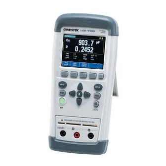
Page 12: Appearance
LCR-1000 Series Appearance Front Panel TFT LCD Function For executing the function indicated for the position corresponding to the Function key. Soft keys for selecting the... - Page 13 GETTING STARTED corresponding option located below the LCD screen. Measure This key is used for entering the measurement display area page. System This key is used for entering system setup page. Power Press the power button for about 2 seconds, the instrument will turn on, the green light of the power button will be on, and the battery power is used.
- Page 14 LCR-1000 Series Top Panel USB port (Type C) This port is used for remote control and battery charging. Using an external power supply, the measurement accuracy will not be guaranteed. Reset When the instrument unexpectedly fails to shut down or freezes, reset and restart the instrument.
-
Page 15: Main Specifications And Features
GETTING STARTED Main Specifications and Features Test Function C-D, C-Q, C-R, L-D, L-Q, L-R, L-Rdc, R-Q, R-X, R-Rdc, Rdc, Z-D, Z-Q, Z-θr, Z-θd Equivalent Circuit Series (subscript s), parallel (subscript p). Actual capacitors, inductors, and resistors are not ideal components of pure reactance and pure resistance. - Page 16 LC oscillator circuit. Test Frequency LCR-1100: 50Hz, 100Hz, 120Hz, 1kHz, 2kHz, 10kHz, 50kHz and 100kHz LCR-1010: 50Hz, 100Hz, 120Hz, 1kHz, 2kHz, 10kHz Accuracy: 0.02%...
- Page 17 Test frequency: 1kHz, range: HOLD Fast: 10 times/s Slow: 2.5 times/s Basic Accuracy 0.2% Display Range Table 2-2 Function Display Range 0.001H ~ 999.9H LCR-1100 Measurement 0.001pF ~ 999.9mF 0.0001Ω ~ 99.99M Display Range R﹑X﹑Z﹑Rdc 0.0001 ~ 9.999 0.0001 ~ 999.9 θd -179.99°~179.99°...
- Page 18 LCR-1000 Series System Settings Data hold function. Measurement parameter settings are automatically saved Touch screen settings Power saving mode settings (Automatic power off, APO; Screen dimming time setting, DIM DISPLAY; Screen brightness adjustment, BRIGHTNESS) Interface The instrument supports USB communication interface, which can be set as HID and virtual serial port (VCOM) two interfaces.
-
Page 19: Connection Of Test Terminal
GETTING STARTED Connection of test terminal The instrument has two kinds of test ports: five-terminal and three- terminal test ports. If you want to meet the accuracy specification of the instrument, you must use the five-terminal test terminal, and the lower accuracy of the three-terminal test will not guarantee the specification. -
Page 20: Battery Installation And Replacement
LCR-1000 Series Battery installation and replacement The instrument has a built-in rechargeable lithium battery, which has been installed in the battery compartment of the instrument at the factory. If replacing the battery, follow the steps below Squeeze the axis of the instrument bracket inward, and remove the bracket. -
Page 21: Battery And Power Supply
GETTING STARTED Battery and Power supply Please turn off the instrument for USB charging, and try to avoid using it while charging. The USB can only charge the battery, cannot supply power for the operation of the instrument. Use a USB charger that meets CE or UL specifications to charge the instrument to avoid personal injury or instrument damage caused by bad chargers. - Page 22 LCR-1000 Series Battery level (white): Sufficient power. charging/battery Battery level (orange): Low power. status display: (upper right Battery level (red): Very low and almost corner) dead. Battery level + lightning (orange): Charging. Battery level + screen: Remote control, not charging. Avoid wrong connection, which would lead to Note incorrect reading value.
-
Page 23: Measure
MEASURE EASURE At any time, you can enter the [MEAS DISPLAY] page by pressing the MEAS key. Use the direction key to move the cursor to the setting item, the optional parameters will be displayed at the bottom of the LCD, press the corresponding function key to set. -
Page 24: Func
Phase angle of impedance(degree) θ Phase angle of impedance(radian) Quality Factor, (Q = 1/D) Dissipation Factor , Loss coefficient (tanδ) Reactance FREQ Measurement frequency. Frequency Accuracy: 0.02% LCR-1010:50Hz, 100Hz, 120Hz, 1kHz, 2kHz, 10kHz LCR-1100:50Hz, 100Hz, 120Hz, 1kHz, 2kHz, 10kHz, 50kHz, 100kHz... -
Page 25: Level
MEASURE LEVEL Measurement signal level. Level Accuracy: 10% 3 levels: 0.3Vrms, 0.7Vrms, 1.0Vrms RANGE There are 8 ranges, including: 10Ω, 100Ω, 300Ω, 1kΩ, 3kΩ, 10kΩ, 30kΩ, 100kΩ. AUTO Automatically selects the range. The instrument will select the appropriate range according to the impedance|Z| of the device under test. -
Page 26: Equ
LCR-1000 Series Equivalent Circuit methods: Series (SER) and Parallel (PAL). Provide equivalent mode selection for R, L, and C, and obtain the measurement parameters of Rs/Rp, Ls/Lp, and Cs/Cp. SPEED Measurement speed: SLOW and FAST Slow: 2.3 times/s (1kHz, AUTO). Fast: 8 times/s (1kHz, AUTO). -
Page 27: Setup
SETUP ETUP At any time, you can enter the [SETUP] page by pressing the SETUP key. Use the direction key to move the cursor to the setting item, the optional parameters will be displayed at the bottom of the LCD, press the corresponding function key to set. -
Page 28: Auto Lcz
LCR-1000 Series AUTO LCZ AUTO LCZ function can automatically help to select the best parameters and the best equivalent circuit method. If the range is set to auto, the LCR will be in a fully automatic test state. After AUTO-LCZ is turned on, the FUNC item will display [AUTO-LCZ] and the EQU item will display [AUTO]. -
Page 29: Beep
SETUP BEEP 2 kinds of beep functions: qualified and bad beeps, which are used to prompt the test results with beeps. When powered by an external power source, the beep will beep continuously until the status changes. When on battery power, the beep will beep short until the status changes. - Page 30 LCR-1000 Series KEYPAD After pressing the [KEYPAD INPUT] key, the INPUT keyboard input box will be displayed. Use your finger to lightly touch the number keys on the touch screen to enter the nominal value or use the direction keys to select a number and then press the key to enter the nominal value.
-
Page 31: Tol(±)
SETUP TOL(±) If the COMP function is enabled, the calculation result needs to set a percentage threshold to judge PASS or FAIL. Use the touch screen keyboard to enter the relative deviation (percentage deviation), and also provide 4 common values: 1%, 5%, 10% and 20%. - Page 32 LCR-1000 Series PEN/SHORT Prior to measurement, the user needs to correct the fixture to eliminate stray capacitance and series impedance that may be generated by the fixture. When the instrument is turned on, in order to achieve the accuracy of the technical indicators, please perform open circuit test and short circuit test before measuring after warming up the instrument.
-
Page 33: Open/Short
OPEN/SHORT Open test Open correction capability cancels errors due to the stray admittance(G,B) in the test fixture. Figure Stray admittance Function Enable or Disable the open circuit ON/OFF correction function. MEAS OPEN Open correction for LCR only. DCR OPEN Open correction for DCR only. Steps 1. - Page 34 LCR-1000 Series 4. Press [OK] to start correction. During correction, the LCD will display a progress bar, and you can press the [CANCEL] key to cancel the correction. 5. After the correction is completed, the LCD will prompt: LCR/DCR correction finished. If the correction fails, the LCD will prompt: LCR/DCR correction fail! Please check if there is any error?
-
Page 35: Short Test
OPEN/SHORT Short test Short correction compensates for any residual impedances (R,X), such as the impedance of the cables and the DUT connection points. Figure Residual impedances ON/OFF Enable or Disable the short circuit correction function. MEAS SHORT Short correction for LCR only. DCR SHORT Short correction for DCR only. - Page 36 LCR-1000 Series 4. Press [OK] to start correction. During correction, the LCD will display a progress bar, and you can press the [CANCEL] key to cancel the correction. 5. After the correction is completed, the LCD will prompt: LCR/DCR correction finished. If the correction fails, the LCD will prompt: LCR/DCR correction fail! Please check if there is any error?
-
Page 37: System Config
SYSTEM CONFIG YSTEM CONFIG At any time, you can enter the [SYSTEM CONFIG] page by pressing the SYST key. Use the direction key to move the cursor to the setting item, the optional parameters will be displayed at the bottom of the LCD, press the corresponding function key to set. -
Page 38: Key Beep
LCR-1000 Series KEY BEEP Turn ON or OFF key and touch screen sounds. BRIGHTNESS The instrument has two sections of LCD screen brightness for adjustment: 50%, 100% When powered by external power supply, the screen brightness will be automatically adjusted to 100% When the battery is powered, if you want to extend the working time, you can use 50% brightness to reduce the power consumption of the instrument. -
Page 39: Touch Panel
SYSTEM CONFIG TOUCH PANEL The instrument can complete the measurement operation by using the direction building and function keys. However, when a value needs to be input, a touch screen is required to assist input. When the input box is opened, if the touch screen is closed, it will be automatically opened for use. - Page 40 LCR-1000 Series Touch screen 1. Touch screen calibration requires a touch calibration steps pen, which can be calibrated with a mobile phone/tablet touch pen. It is not recommended to use fingers to calibrate the touch screen, because the finger contact point is large and inaccurate. Press the CALIBRATE function key to enter the calibration page.
- Page 41 SYSTEM CONFIG 3. Calibrate the second point: touch the cross in the lower right corner. 4. Calibration complete. Tap the screen to exit the calibration process.
-
Page 42: Dim Display
LCR-1000 Series DIM DISPLAY Decrease backlight brightness time setting. When the instrument is powered by batteries, it can be set that no button and touch screen operations are performed within a specified period of time, and the screen backlight can be actively reduced to save battery power. -
Page 43: Vcom Endmark
SYSTEM CONFIG VCOM ENDMARK USB virtual serial port terminator. LCR-1000 series has a built-in USB-VCOM virtual serial port for communication with the host computer. USB-VCOM supports the following configurations: Data bits: 8 bits Stop bit: Adaptive, 1 or 2 bits ... -
Page 44: Usb-Hid Pid
LCR-1000 Series USB-HID PID Instrument ID setting. LCR-1000 series has a built-in standard USB-HID communication interface for high-speed communication with the host computer. By setting the PID of USB-HID, the host computer can establish communication with up to 8 LCR-1000s. Before multi-machine communication, be sure to set the PID of each instrument to a different PID. -
Page 45: Default Set
SYSTEM CONFIG DEFAULT SET Reset settings to factory defaults. The factory settings are as follows: SETUP SYSTEM FUNC: C-D KEY BEEP: ON FREQ: 1kHz TOUCH PANEL: DISABLE LEVEL: 1.0V DIM DISPLAY: 5 minutes RANGE: AUTO APO: 10 minutes EQU: SER VCOM ENDMARK: LF SPEED: SLOW USB-HID PID: 1000... -
Page 46: System Information
LCR-1000 Series SYSTEM INFORMATION Displays the model, serial number , firmware/hardware/USB version and USB VID/PID of the instrument. This page has no user configurable options. -
Page 47: Measurement Examples
MEASUREMENT EXAMPLES EASUREMENT EXAMPLES To measure a thin film ceramic capacitor, explain how to measure the capacitance value. Before testing, please determine the following measurement conditions according to the specifications of the capacitor. DUT: film capacitor Test fixture: If the capacitor can be directly inserted into the test terminal of the instrument, there is no need to connect another fixture. - Page 48 LCR-1000 Series Please follow the OPEN/SHORT chapter to perform open circuit and short circuit zero reset calibration. Insert the capacitor into the test slot of the instrument or connect the capacitor with a test fixture. Read the test result. Figure Test results for capacitors ...
-
Page 49: Remote Control
REMOTE CONTROL EMOTE CONTROL LCR-1000 has a USB Type-C interface, which provides a virtual serial port (VCOM) or USB- HID class to connect and control with a computer. Connect to PC to ensure measurement accuracy LCR-1000 needs to be connected to PC for command control measurement. -
Page 50: Usb-Vcom Virtual Serial Port
LCR-1000 Series USB-VCOM virtual serial port LCR-1000 connected to PC, it will automatically install the driver and create a virtual serial port. The serial port number needs to be viewed in the Device Manager (Device Manger): USB-VCOM follows the standard serial protocol for communication. -
Page 51: Usb-Hid Device Class
REMOTE CONTROL USB-HID device class LCR-1000 provides USB-HID class, which can be automatically identified by Windows when connected to a PC. Therefore, the user does not need to install the driver, and the instrument can be installed automatically under the Windows system (as shown below), and the user can use the Windows internal API function to complete the control of the instrument. - Page 52 LCR-1000 Series Here, CreateFile is used to open the HID device, where the device path is obtained through the function SetupDiGetInterfaceDeviceDetail. ReadFile( hDev, // Device handle, which is the return value of CreateFile recvBuffer, // Buffer for receiving data IN_REPORT_LEN, // The length of the data to be read &recvBytes, // The number of bytes of data actually received...
- Page 53 REMOTE CONTROL...
-
Page 54: Command Overview
LCR-1000 Series OMMAND OVERVIEW The LCR-1000 instruction set is common to both USB-HID and USB-VCOM. The difference is that USB-HID needs to be packaged and used, while USB-VCOM can be used directly. USB-HID command package The command packet format sent by the PC (a packet structure defined in C language, other language formats must be similar): #define program pack(1) typedef __packed struct... -
Page 55: Specifiers
0x00 (Note: not the ASCII number 0). A received packet (instrument side) is as follows: ASCII format: GwINSTEK,LCR-1100,0,REV A1.0 Specifiers When describing the directive, we use some specifiers, these specifiers are not part of the directive, just for the convenience of explanation, please don't include it when passing the directive. -
Page 56: Data Types
LCR-1000 Series Data types LCR-1000 supports multiple data types Table Format Description Example List of data <NR1> Integer 100, +100, -100 formats <NR2> Real number 1.23, +1.23, -1.23 <NR3> floating 1.23E4, +1.23E4, - point 1.23E4, -1.23e-4 number <NR4> Floating 1.23K, 1.23N, 1.23U point (see the table below number with... -
Page 57: Command List
COMMAND OVERVIEW Command List Summary of all USB commands Command (sHeader) Parameter (sPara) Description DISP:PAGE MEAS|SETUP|SYSTem|CSET Switch display page |SINF DISP:PAGE? Query the name of the currently displayed page DISP:LINE String(maximum 28 Display the string in the characters) bottom prompt bar FUNC C-D|C-Q|C-R|L-D| L-Q|L-R|L- Set the measurement... - Page 58 LCR-1000 Series CORR:OPEN:STAT ON|OFF|1|0 Open circuit reset switch CORR:OPEN:STAT? Query the open circuit reset switch CORR:SHOR:STAT ON|OFF|1|0 short circuit reset switch CORR:SHOR:STAT? Query the short circuit reset switch CORR:OPEN:LCR Execute LCR open circuit clear CORR:SHOR:LCR Execute LCR short circuit clear CORR:OPEN:DCR Execute DCR open circuit clear...
-
Page 59: Commands
COMMAND OVERVIEW Commands DISP:PAGE <meas|setup|system> DISP:PAGE? Function: It sets or queries the display page. Description: Set parameter <MEAS|SETUP|SYSTem|CSET|SINF> Set syntax DISP:PAGE Query syntax DISP:PAGE? Return data <meas|setup|cset|sinf|system> Note MEAS: Measurement display page SETUP: Setup page SYSTem: System page ... - Page 60 LCR-1000 Series FUNC <C-D, C-Q, C-R, L-D, L-Q, L-R, L-Rdc, R-Q, R-X, R-Rdc, Rdc, Z-D, Z-Q, Z-θr, Z-θd> FUNC? Function: It sets or queries the measurement parameters. Description: Set parameter <C-D|C-Q|C-R|L-D|L-Q|L-R|L-Rdc|R-Q| R-X|R- Rdc|Rdc|Z-D|Z-Q|Z-thr|Z-thd> Set syntax FUNC Query syntax FUNC? Return data <C-D|C-Q|C-R|L-D|L-Q|L-R|L-Rdc|R-Q|R-X| R- Rdc|Rdc|Z-D|Z-Q|Z-thr|Z-thd>...
- Page 61 COMMAND OVERVIEW FUNC:LCR:RANG <0|1|2|3|4|5|6|7> FUNC:LCR:RANG? Function: It sets or queries the LCR measurement range. Description: Set parameter <0|1|2|3|4|5|6|7> 0~7 represents the range number Set syntax FUNC:LCR:RANG Query syntax FUNC:LCR:RANG? Return data <0|1|2|3|4|5|6|7> FUNC:DCR:RANG <0|1|2|3|4|5|6|7> FUNC:DCR:RANG? Function: It sets or queries the DCR measurement range. Description:...
- Page 62 The frequency values for each model are as follows: LCR-1010: 50|100|120|1k|2k|10k LCR-1100: 50|100|120|1k|2k|10k|50k|100k APER <SLOW|FAST> APER? Function: It sets or queries the test speed. Description: Set parameter <SLOW|FAST>...
- Page 63 COMMAND OVERVIEW result> Note The instrument returns the test results of the primary and secondary parameters NR3 type. If the secondary parameter is closed, it will return data +0.000000e+00 Example: +7.929158e-15,+0.000000e+00 COMP <ON | OFF | 0 | 1> COMP? Function:...
- Page 64 LCR-1000 Series COMP:TOL <NR1|NR2|NR3> COMP:TOL? Function: It inputs and queries the percentage deviation. Description: Set parameter <NR1|NR2|NR3> any form of data, the input data is percentage data (no need to divide by 100), Do not enter the percent sign %, Example: COMP:NOM 2 //Indicates 2% Set syntax COMP:TOL Query syntax COMP:TOL?
- Page 65 COMMAND OVERVIEW CORR:OPEN:LCR Function: It executes LCR open circuit correction. Description: Set syntax CORR:OPEN:LCR Return data <pass|fail> Note “LCR open” is prompted when the correction starts Prompt “pass or fail” after correction CORR:SHORT:LCR Function: It executes LCR short circuit correction. Description:...
- Page 66 LCR-1000 Series CORR:SHORT:DCR Function: It executes DCR short circuit correction. Description: Set syntax CORR:SHORT:DCR Return data <pass|fail> Note “DCR short” is prompted when the correction starts Prompt “pass or fail” after correction SYST:KEYL <ON | OFF | 1 | 0> Function:...
- Page 67 Function: It is used to query the manufacturer, model, serial number and version information of the instrument. Description: Query syntax IDN? Return data manufacturer, model, serial number,version Example: GwINSTEK,LCR-1100,<SN>,REV A1.03 ERR? Function: It queries whether the command sent before is wrong? Description: Query syntax ERR?
-
Page 68: Specifications
LCR-1000 Series PECIFICATIONS Specifications If the following conditions are met during the measurement, the measurement result can reach the basic accuracy. Warranted performance. All specification apply at 23 ± 5 °C, unless otherwise stated, and 30 minutes after the instrument has been turned on. - Page 69 Auto range、 Hold range Speed Slow 2.5 times/sec、Fast 10 times/sec Level 0.3V, 0.7V and 1.0Vrms, Accuracy: 10% Frequency LCR-1010: 50Hz, 100Hz, 120Hz, 1kHz, 2kHz, 10kHz LCR-1100: 50Hz, 100Hz, 120Hz, 1kHz, 2kHz, 10kHz, 50kHz , 100kHz Accuracy: 0.02% Output 100Ω, Accuracy: 5% Impedance(RO) Correction Open、Short...
-
Page 70: Accuracy
LCR-1000 Series Accuracy The following accuracy guarantees can only be provided by using a five-wire terminal test socket or a connection test fixture for measurement. Measurements are made using 3-wire terminal sockets for quick measurement reference only. Test Cable Use the five-wire terminal test socket to measure directly, and the accuracy error is only shown in the table. - Page 71 SPECIFICATIONS Accuracy C and D 50Hz/60Hz/100Hz/120Hz Range Display range Accuracy Ce Accuracy De 20mF 5.0000mF - 50.000mF 2.0%+5 counts 0.0200 500.0F - 4.9999mF 1.0%+3 counts 0.0100 0.5%+2 counts 0.0050 500F 50.00F - 499.99F 5.000F – 49.999F 0.35%+2 counts 0.0020 50F 500.0nF –...
- Page 72 LCR-1000 Series Accuracy L and Q 50Hz/60Hz/100Hz/120Hz Range Display range Accuracy Le Accuracy Qe 500.0H – 1000.0H 1000H 1.0%+3 counts 0.0100 500H 50.00H - 499.99H 0.3%+2 counts 0.0030 5.000H – 49.999H 0.2%+2 counts 0.0020 500.0mH – 4.9999H 0.2%+2 counts 0.0020 50.00mH –...
- Page 73 SPECIFICATIONS Accuracy Z and <=10kHz Accuracy e Range Display range Accuracy Ze 3.0%+5 counts 10M 5.000M - 10.000M 2.0 5M 500.0k - 4.9999M 1.2%+3 counts 0.7 500k 50.00k - 499.99k 0.3%+3 counts 0.2 0.2%+2 counts 50k 5.000k - 49.999k 0.2...
- Page 74 LCR-1000 Series Accuracy ESR and Φ ESR is equal to the series equivalent resistance (Rs) [Ω] ESR accuracy formula: Where: e is ’s accuracy. Among them, Xx is the measured reactance value 2 Phase Angle Accuracy: Where: Lx is the measured L value.
- Page 75 SPECIFICATIONS Accuracy DCR DCR Range Display range Accuracy 3.0%+5 counts 10M 5.000M - 10.000M 1.2%+3 counts 5M 500.0k - 4.9999M 0.3%+3 counts 500k 50.00k - 499.99k 50k 5.000k - 49.999k 0.2%+2 counts 5k 500.0 - 4.999k 0.2%+2 counts 0.2%+2 counts 500...
-
Page 76: Dimensions
LCR-1000 Series Dimensions...
Need help?
Do you have a question about the LCR-1100 and is the answer not in the manual?
Questions and answers