GW Instek LCR-800 User Manual
Precision lcr meter
Hide thumbs
Also See for LCR-800:
- User manual (40 pages) ,
- User manual (72 pages) ,
- User manual (42 pages)
Table of Contents
Advertisement
Quick Links
Precision LCR Meter
LCR-800
USER MANUAL
GW INSTEK PART NO. 82CR-81900MK1
ISO-9001 CERTIFIED MANUFACTURER
This manual contains proprietary information, which is protected by
copyright. All rights are reserved. No part of this manual may be
photocopied, reproduced or translated to another language without
prior written consent of the Good Will Instrument company.
The information in this manual was correct at the time of printing.
However, Good Will continues to improve products and reserves the
right to change specifications, equipment, and maintenance
procedures at any time without notice.
Good Will Instrument Co., Ltd.
No. 7-1, Jhongsing Rd., Tucheng City, Taipei County 236, Taiwan.
Advertisement
Chapters
Table of Contents

Subscribe to Our Youtube Channel
Related Manuals for GW Instek LCR-800


Summary of Contents for GW Instek LCR-800
- Page 1 Precision LCR Meter LCR-800 USER MANUAL GW INSTEK PART NO. 82CR-81900MK1 This manual contains proprietary information, which is protected by copyright. All rights are reserved. No part of this manual may be photocopied, reproduced or translated to another language without prior written consent of the Good Will Instrument company.
-
Page 2: Table Of Contents
SAFETY INSTRUCTIONS LCR-800 User Manual INTERACE ..............111 Table of Contents RS232 Interface Configuration ... 112 Signal Overview ......... 116 SAFETY INSTRUCTIONS ........... 5 FAQ ................121 GETTING STARTED ............10 APPENDIX ..............123 Main Features ........11 Fuse Replacement ......123 ... -
Page 3: Safety Instructions
Do not disassemble the LCR-800 unless you are qualified as service personnel. These safety symbols may appear in this manual or on the LCR-800. (Measurement categories) EN 61010-1:2001 specifies the measurement categories and their requirements as follows. LCR-800 Warning: Identifies conditions or practices that falls under category I. - Page 4 Temperature: 10°C to 50°C (Pollution Degree) EN 61010-1:2001 specifies the pollution degrees and their requirements as follows. LCR-800 falls under degree 2. Pollution refers to “addition of foreign matter, solid, liquid, or gaseous (ionized gases), that may produce a reduction of dielectric strength or surface resistivity”.
- Page 5 SAFETY INSTRUCTIONS LCR-800 User Manual Power cord for the United Kingdom When using the LCR-800 in the United Kingdom, make sure the power cord meets the following safety instructions. ETTING STARTED NOTE: This lead/appliance must only be wired by competent persons This chapter describes the instrument’s main...
-
Page 6: Getting Started
GETTING STARTED LCR-800 User Manual Main Features Model comparison 12Hz ~ 200kHz wide test frequency (LCR-821) LCR model Performance 5 digit measurement resolution Test Frequency 2V DC bias voltage • (12Hz~200kHz) 0.05% basic measurement accuracy (LCR- ... -
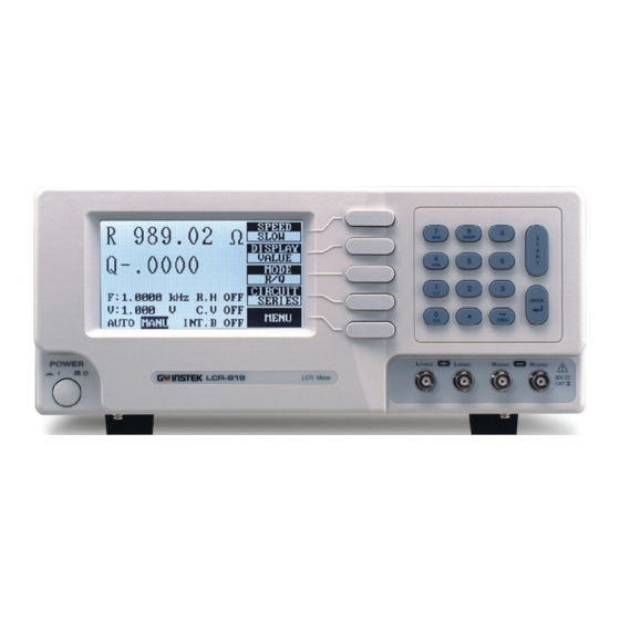
Page 7: Front Panel Overview
GETTING STARTED LCR-800 User Manual The bias key selects an internal or 7. Bias Front Panel Overview external bias. The bias will be displayed on the bottom of the LCD display as INT.B (internal bias) or EXT.B (external bias). The On/Off key turns the internal 8.On/Off... -
Page 8: Rear Panel Overview
GETTING STARTED LCR-800 User Manual The Start key is used to start Start Rear Panel Overview measuring when in manual mode. The start key can also be used to select automatic or manual measuring modes. Hold the Start key for 3 seconds to toggle between auto and manual mode. -
Page 9: Power Up
GETTING STARTED LCR-800 User Manual The fuse holder contains the main Fuse / Power Power Up fuse, 5TT 3A/250V. For fuse Socket replacement details, see page 123. The mains socket accepts the Tilt stand power cord. See page 18 for power-up details. -
Page 10: Fixture Connection
GETTING STARTED LCR-800 User Manual Counter- Clockwise: Fixture Connection clockwise: dark bright Fixture structure The standard fixture is a four-wire type (Kelvin 4 Background wire). The outer terminals (Hforce and Lforce) provide the current and the inner terminals (Hsense and Lsense) measures the potential. - Page 11 GETTING STARTED LCR-800 User Manual H side Fixture connection Panel operation 1. Discharge the test component before connecting the fixture set. L side 2. Connect the Kelvin clip test lead into the front 4. If the test component has an outer case terminals.
-
Page 12: Zeroing
EXTERNAL BIAS zeroing process should be performed again. All 200mA data performed during the calibration is stored in the internal memory of the LCR-800. Don’t connect The Open circuit calibration determines the stray admittance and compensates high impedance measurements. The short calibration determines the residual impedance and is used when determining low impedance measurements. -
Page 13: Component Measuring Guidelines
GETTING STARTED LCR-800 User Manual If the test failed, ensure your cables or test fixtures are Component Measuring Guidelines Warning open and not shorted. Ensure R.H is OFF. After inspection try again. Background For measuring Impedance, Capacitance, The short test will calibrate the short circuit... - Page 14 GETTING STARTED LCR-800 User Manual Air-cored coils can pick up noise very easily, Air-cored coils therefore they should be kept well clear of any test Capacitors are usually measured in series except General equipment that may contain power transformers or Capacitors for extremely small capacitance.
-
Page 15: Basic Measurement
124. Basic Measurement details how to measure Measurement combination individual components and how to configure the LCR-800 settings. Basic Measurement also :Available, :Not available describes how to save and recall memory. -
Page 16: Parameter Configuration
All measurement unit results can be displayed as units the absolute values, delta values or delta percentage values. The LCR-800 series support 3 different Measurement Value will show the absolute value of the Speed measurement speeds: slow, medium or fast at measurement in Ohms (Ω), Henries (H) or Farads... -
Page 17: Select Equivalent Circuit Type
Measurement Modes CIRCUIT menu key to cycle between the series or parallel equivalent circuits. Measurement The LCR-800 has a number of different mode measurement modes. Primary and secondary measurements are displayed on the screen simultaneously. For detailed information regarding the measurement combinations, see the... - Page 18 BASIC MEASUREMENT LCR-800 User Manual 1. Press the 7/Bias key on the number The LCR-821 can provide 504 different frequencies Panel operation pad to cycle from internal to with a 5 digit resolution including decimal places. external bias. The bottom of the...
-
Page 19: Set Measurement Voltage
BASIC MEASUREMENT LCR-800 User Manual 1.1kHz The nearest frequency will be selected from the 504(LCR-281) nominal frequencies, and updated in the display. Here, the nearest frequency to 1.1kHz is 1.0909kHz. After the test frequency has been changed, the zeroing Note must be performed again. -
Page 20: Set Constant Voltage Source
BASIC MEASUREMENT LCR-800 User Manual Set Range hold Background When DUTs are disconnected from the test cables/fixtures during continuous testing, Range Hold can be used to avoid range switching. This is particularly useful for repetitively testing a number of DUTs. For more information on Range and range hold, see the specifications, page 136. -
Page 21: Set Nominal Values
2. Press EXIT to exit to the main menu. Set Nominal Values The LCR-800 series are able to set nominal values Background when using the DELTA and DELTA% measuring modes. Nominal values can be set to up to 5 digits The NOM.VAL key and screen will be updated... -
Page 22: Running Measurement
BASIC MEASUREMENT LCR-800 User Manual Running Measurement Select Automatic measurement Select Single measurement Background Measurement can be manually controlled (MANU) or automatically updated (AUTO). In continuous mode (AUTO), measurements are Measurements can be manually controlled Background automatically done and the display is updated (MANU) or automatically updated (AUTO). -
Page 23: Store Recall
Store Recall accordingly. Store or Recall Memory Settings MEMORY RECALL NO: VOLT VOLTAGE= 1.000 The LCR-800 series have 100 blocks of memory 1.000 Background AVGE available for saving settings. AVERAGE= All memory is stored using an internal battery. The RECALL CALIBRATION... -
Page 24: Bin Functions
LCR-800 User Manual 2. Press 1 to recall the calibration settings or 2 to cancel. IN FUNCTIONS The Handler interface is used to sort components 3. When the status bar has completed, into different bins. The handler menu compares the calibration settings are recalled. -
Page 25: Binning Menu
BIN FUNCTIONS LCR-800 User Manual Bin Summary Menu Overview ........68 Bin Summary Bin Summary/Results ..........70 Binning Menu Menu Handler Menu Overview Mode Setting The mode setting area shows basic settings for the current bin mode. SET BIN Configures the Bin settings... -
Page 26: Handler Menu
BIN FUNCTIONS LCR-800 User Manual Parameter 1,2,3,4 Handler Menu Delay Delay between each measurement Parameter 0~99999 ms Background Before Bin Sorting, the measurement settings must MANU/ Selects between automatic and manual be configured. AUTO mode Parameter Auto, Manu Panel operation 1. -
Page 27: Circuit Setting
BIN FUNCTIONS LCR-800 User Manual Circuit Setting Display Setting Use Circuit setting to change the equivalent circuit. Background Background Use the Display setting to change the measurement results as values or bins. Panel Operation 1. Use the arrow menu keys (F1/F2) to move the cursor to CIRCUIT. -
Page 28: Select/Run Auto/Manu Sorting
BIN FUNCTIONS LCR-800 User Manual Select/Run Auto/Manu Sorting Set the test mode from manual to automatic. Background Voltage Setting 1. Hold the START key for a few Panel operation seconds to toggle from automatic or manual bin sorting. Set the testing voltage. -
Page 29: Bias Setting
BIN FUNCTIONS LCR-800 User Manual Bias Setting Range Setting Set internal or external bias voltage. Background Background The range can be selected from 1 to 4. Different ranges should be used for different components and component values and to ensure accurate Panel Operation 1. -
Page 30: Delay Setting
BIN FUNCTIONS LCR-800 User Manual 2. Press ON (F3) to turn constant Average Setting voltage on. 3. Press OFF (F4) to turn constant Background The average function chooses how many averages voltage off. (1-255) are used for each measurement. Panel Operation 1. Use the arrow menu keys (F1/F2) Delay Setting to move the cursor to AVERAGE. -
Page 31: Set Bin Menu
BIN FUNCTIONS LCR-800 User Manual Q_Max Sets the Maximum Q value for the Set Bin Menu current bin. Q_Min Sets the minimum Q value for the current bin. Set Bin Menu Overview Menu Keys Scroll up through the menu items Scroll down through the menu items Clears the current bin settings. -
Page 32: Sort Type
BIN FUNCTIONS LCR-800 User Manual 2. Use the arrow menu keys (F1/F2) Bin Number to move the cursor to SET BIN. Background Up to 13 sorting bins can be configured, with a minimum of 1 bin. Panel operation 1. Move the cursor to TOT_BIN in the 4. -
Page 33: Set Max/Min Absolute Limit
BIN FUNCTIONS LCR-800 User Manual example: 20 Ω. 2. Use the number pad to enter the maximum percentage value for the current sort bin. Set Max/Min Absolute Limit example: 10%. The maximum and minimum absolute limits of the Background 3. Repeat the above procedure for -%. -
Page 34: Bin Summary Menu
BIN FUNCTIONS LCR-800 User Manual Bin Summary Menu Clear Bins Bin Summary Menu Overview All the bin settings can be cleared for all the bins. Background 1. Press NEXT BIN until BIN1 is the Panel operation current bin. Ω Parameters 2. - Page 35 BIN FUNCTIONS LCR-800 User Manual Indicates that a test result is greater than the maximum limit. Bin Summary/Results PHI= Primary Hi Indicates that a test result is less than the Background After the bins have been set up (page 61) and minimum limit.
- Page 36 BIN FUNCTIONS LCR-800 User Manual 5. To clear the test results, press CLR followed by F3 (YES->) to confirm. S232 REMOTE 6. Press EXIT to exit the bin summary results. The LCR-821 (LCR-816/817/819 as options) includes RS232C remote connectivity. With the...
-
Page 37: Rs232 Remote
LCR-800 User Manual LCR Setup LCR Viewer RS232 Settings LCR VIEWER Display Overview RS232 must first be enabled on the LCR-800 before LCR-Viewer mimics the LCR-800 series front panel Background Background trying to connect with a PC. and operates in a similar manner. -
Page 38: Lcr Viewer Connection And File Settings
Please ensure LCR Viewer has been installed. Connection 1. Connect the LCR meter to the PC Settings with an RS232 cable. 2. Ensure the LCR-800 is set to Page 43 manual (single) measurement mode. 3. Ensure RS232 has been enabled on Page 73 the LCR meter. -
Page 39: Lcr Viewer File Settings
File Number Identifier Identifier Test Result File_Name File_Num Filename 1~10000 LCR_ 0001 LCR_0001.txt 10001~20000 LCR_ 0002 LCR_0002.txt 99980001~ LCR_ 9999 LCR_9999.txt 99990000 1. Ensure the LCR-800 is set to Page 80 manual (single) measurement mode. 2. Go to the OptionSettings menu. -
Page 40: Lcr Viewer Remote Measurement
LCR Viewer Remote Measurement directory from the drop down selections. Background The LCR Viewer Software mimics the LCR-800 meter front panel. Remote operation is identical. 4. Type a file name To operate any of the controls remotely, a mouse identifier in the must be used. -
Page 41: View Data
For more information on the way the files store test results see page 78. The Help menu is to view the software version and Background copyright information 1. Ensure the LCR-800 is set to Page 80 manual (single) measurement 1. Ensure the LCR-800 is set to Page 80 Operation mode. -
Page 42: Terminal Connection
RS232 REMOTE LCR-800 User Manual Terminal Connection Configure Terminal Connection To connect the LCR-800 to a terminal program, Background follow the instructions below. 1. Connect the LCR meter to the PC Connection Settings with an RS232 cable. 2. Ensure the LCR-800 is set to... - Page 43 ^END^M or ^J^M as the terminal characters. Terminal command: COMU? LCR Return: COMU:ON.. Terminal command: COMU:OVER LCR Return: COMU:OVER 8. The LCR-800 will display RS232 ONLINE when the connection is successful. 9. See the Programming chapter for Page 87 remote programming details.
-
Page 44: Programming
+32.0000< ^END^M> or <^J^M> 53 4F 52 54 4E 4F 4D 56 2B 33 32 2E 30 30 30 30 Command overview lists all the LCR-800 0A 0D commands and command queries. The command syntax section shows you the basic rules you have... -
Page 45: Commands
PROGRAMMING LCR-800 User Manual -1.0000 -1.0000 2D 31 2E 30 Output Commands 30 30 35 As can be seen above, positive input numbers use SPEED ................91 the ASCII “+” whilst the output will use a “sp” DISPLAY ............... 91 ... -
Page 46: Speed
Set the measurement speed to slow. Currently the display is set at value. Query Syntax MAIN:SPEE?<^END^M>or<^J^M> Return String MODE Command/Query <string> Speed MAIN:SPEE:SLOW<^END> Slow The mode command sets the measurement mode of the LCR-800. MAIN:SPEE:MEDI<^END> Medium Syntax MAIN:MODE:<string><^END^M>or<^J^M> MAIN:SPEE:FAST<^END> Fast Parameter Query Example MAIN:SPEE?<^END^M> <string>... -
Page 47: Circuit
PROGRAMMING LCR-800 User Manual MAIN:CIRC:PARA<^END> Parallel Example MAIN:MODE:RQ<^END^M> Query Example MAIN:CIRC?<^END^M> MAIN:CIRC:PARA<^END> Sets the mode to R/Q (Resistance/Quality factor) Returns a parallel equivalent circuit as the current Query Syntax MAIN:MODE?<^END^M>or<^J^M> setting. Return String <string> Current measurement FREQUENCY Command/Query mode MAIN:MODE:RQ<^END>... -
Page 48: Auto/Manu
PROGRAMMING LCR-800 User Manual Returns Auto mode as the current measurement 0.005~1.275 (5 characters, including a 5mV~1.275 mode. decimal) Example MAIN:VOLT 0.005<^END^M> START Command Sets the test signal voltage to 5mV. Query Syntax MAIN:VOLT?<^END^M>or<^J^M> Starts a measurement in manual mode. -
Page 49: Bias
PROGRAMMING LCR-800 User Manual Query Example MAIN:BIAS?<^END^M> MAIN:EXTB:ON..<^END> Command/Query Returns the Bias Status (External Bias is on). Turns Constant Voltage on or off. Queries the constant voltage status. INT.B Command/Query Syntax MAIN:C.V.:<string> <^END^M>or<^J^M> Sets and queries the internal bias. Parameter MAIN:INTB:<string><^END^M>or<^J^M>... -
Page 50: Ppm
PROGRAMMING LCR-800 User Manual Example MAIN:EXTB:OFF.<^END^M> OPEN Command Turn External Bias off. Query Syntax MAIN:EXTB?<^END^M>or<^J^M> This command will perform an open circuit calibration. A return string will indicate if the calibration was successful or not. Return String <string> External Bias status Syntax OFFS:OPEN<^END^M>or<^J^M>... -
Page 51: Recall
PROGRAMMING LCR-800 User Manual Parameter <string> Memory recall status MEMO:NUMB <variable><^END> < variable > Nominal Value OK. Returns the memory (<variable>= 1 ~100) =space character spsp slot used. -XXXXXXX ~ Must be any 8 digit +XXXXXX~-XXXXXX MEMO:RECA:EMPT<^END> +XXXXXXX character including a (Mode dependant) Not Ok. -
Page 52: Average
The average number is currently 255. MODEL NUMBER Query RECALL CALIBRATION Command This query returns the model number of the LCR-800. Recalls the calibration settings from memory. A return string indicates if the command was successful. Query Syntax COMU:MONO<^END^M>or<^J^M> Syntax STEP:RECA<^END^M>or<^J^M>... -
Page 53: On-Line
Resume measurement. (recover measurement). COMU:MONO<^END^M> Query Example COMU:MONO:816.<^END> LEVEL DISPLAY Command The model number is LCR-816 Displays a menu level on the LCR-800 display. Returns the menu level. ON-LINE Query Syntax LEVE:<string><^END^M>or<^J^M> The On-line function queries the RS232 connection status. -
Page 54: Primary Over
PROGRAMMING LCR-800 User Manual <value> Test result <unit1> Primary unit Any 7 digit ASCII including (+) or – Primary measurement nF, pF, uF nanofarads, picofarads, characters and a decimal point. value microfarads MAIN:PRIM 32.705<^END> kΩ, Ω Example = space character) sp, spsp The primary measurement is 32.705 (primary... -
Page 55: Secondary Factor, Primary Unit, Secondary Unit
COMU:OVER<^END> MAIN:SECO .0045nFk<^END> Example Communication initiation has completed. The secondary measurement result is .0045 with kΩ “RS232 ONLINE” will be displayed on the LCR-800 as the unit. The primary unit is nF. display panel. SECONDARY OVER, PRIMARY UNIT, OFF LINE... -
Page 56: Interace
INTERACE LCR-800 User Manual RS232 Interface Configuration Configure RS-232 interface NTERACE DB-9, Male RS-232 Connector configuration 38400 (default) Baud rate This chapter describes basic interface aspects of None Parity the RS-232 and Handler interfaces. Data bit RS232 Interface Configure RS-232 interface ........112... - Page 57 INTERACE LCR-800 User Manual LCR Meter Connection Handler interface DB9 Pin Signal Signal DB9 Pin Connection Connect the male DSUB 25 pin cable to the Handler interface DSR, DCD socket. Pin assignment HANDLER INTERFACE DSR, DCD Signal Function /O_BIN_1 Go, Assigned BIN 1...
-
Page 58: Signal Overview
INTERACE LCR-800 User Manual Pin11 /O_BIN_11 Go, Assigned BIN 11 Signal Overview Pin12 /O_BIN_12 Go, Assigned BIN 12 Pin13 /O_BIN_13 Go, Assigned BIN 13 Background The signal overview section describes the Pin14 /O_S_OVER No-Go/D or Q fail functions and the overall characteristics of the signals used in the handler interface. - Page 59 /O_S_OVER Measurement start signal. This /I_E_TRIG under D_Min, whilst in C/D , R/Q, signal will trigger the LCR-800 to C/R or L/R mode. The signals will go start a measurement when the high at time T4 signal is pulsed for at least 5us. It...
- Page 60 INTERACE LCR-800 User Manual Slow Medium Fast Handler Timing Analog 0.012kHz 817ms 817ms 817ms Measurement time 0.1kHz 901ms 125ms 125ms Background The handler timing characteristics are described in 0.12kHz 901ms 105ms 103ms the timing diagram. Times T1 to T6 are described...
-
Page 61: Faq
LCR-800 User Manual For more information, contact your local dealer or GW Instek at www.gwinstek.com / marketing@goodwill.com.tw. Q1. What is the correct procedure for Open/Short Zeroing when using the LCR-06A test fixture? A1. The LCR-06A test fixture is very sensitive and thus must be used correctly. -
Page 62: Appendix
APPENDIX LCR-800 User Manual Circuit Theory and Formula Series/Parallel circuit models PPENDIX Below are the circuit diagrams and formulas Background describing the six types of series and parallel Fuse Replacement equivalent circuits: Capacitive, Inductive and Resistive. The formulas for all the primary and secondary measurement types are also shown. - Page 63 APPENDIX LCR-800 User Manual Resistance (R) Series diagram Parallel diagram Resistance (R) and Conductance (G = 1/R) Formula Background Resistance measures how difficult it is for the electricity to flow between two terminals. Conductance is the reciprocal of Resistance and measures how easily the electricity flows.
- Page 64 Formula Reactance and Susceptance is only shown for their Note relation to impedance. Reactance and Susceptance are not measurable features of the LCR-800 series. Series Reactance (X Parallel Susceptance (B Type ...
- Page 65 APPENDIX LCR-800 User Manual Impedance (Z) and Admittance (Y = 1/Z) Formula Quality factor (Q) and Dissipation factor (D) Formula Background Impedance measures the total amount of Background Both Quality factor and its reciprocal, Dissipation opposition between two terminals in an AC circuit.
-
Page 66: Accuracy Definitions
APPENDIX LCR-800 User Manual Accuracy Definitions Angle (θ) Formula Primary Measurement Readout Error Formula Background The Angle (θ) measures the phase on which Impedance (Z), Admittance (Y), Quality factor (Q), 2 counts±0.03%+0.02%[(1+Ka) or (X/Ymax ) and Dissipation factor (D) are measured. - Page 67 APPENDIX LCR-800 User Manual R(L/R) 2counts + 0.02%[(1+Ka)* or (Rx/Rmax)* or Q≦1 (Rmin/Rx)*] (1+ | Q│)(1+Kb+Kc)+0.03% Table 1 2counts + 0.02%[(1+Ka)** or (Lx/Lmax)** or Q≧1 KC (Ranges 1,2,3) Frequency & RMS Voltage factor (Lmin/Lx)**] (1+| Q│)(1+Kb+Kc)+0.03% Voltage Frequency 0.03≦V<0.1 0.1≦V<0.25 0.25≦V<1...
-
Page 68: Specifications
APPENDIX LCR-800 User Manual Specifications Table3 Y Range constant- Range Hold Specification accuracy is only applicable when the LCR meter has Component been warmed up for 30 minutes with an operating temperature of Inductor Capacitor Resistor 18°C ~28°C. Range Range1... - Page 69 0.10%(Basic) calibration data backup. (Recommended replacement D, Q 0.001 every three years. Please refer to the accuracy definition *The battery should only be replaced by a GW Instek on page132 for details. approved service center. Basic Accuracy 0.05% LCR-821/819/817 Memory 100 blocks of memory 0.1%...
-
Page 70: Ec Declaration Of Conformity
APPENDIX LCR-800 User Manual Power Source Line Voltage 100V~240V AC, 50~60Hz/ 400Hz EC Declaration of Conformity Power Consumption 45 Watts maximum Fuse Slow-blow 5X20 mm, 3A/250V UL/CSA 5TT GOOD WILL INSTRUMENT CO., LTD. No. 7-1, Jhongsing Rd., Tucheng City, Taipei County 236, Taiwan Dimensions 330mm (W) ×... -
Page 71: Index
INDEX LCR-800 User Manual specification ......136 timing ........119 Display unit settings Handler menu ......52 Impedance handler menu ......54 Dissipation accuracy definition ....132 accuracy definition ....132 overview ....... 129 NDEX Dissipation factor Inductance overview ....... 130 accuracy definition .... - Page 72 INDEX LCR-800 User Manual Resistance Test voltage Weight wire capacitance ....27 Memory accuracy definition ....132 specification ......138 specification ......139 Tilt stand ........18 specification ......138 overview ....... 126 X variable accuracy definition ....133 Mode settings series/parallel model ..
- Page 73 INSTEK LCR METER-RS232 CODE Ver 2.2 2010/05/03 Command Reference Message Terminator (Last data byte with END message) <NL^END> or <NL^J> : New Line or ASCⅡ Line Feed Character (Hex 0A). <CR^M> : ASCⅡ Carry Return Character (Hex 0D) CONTENTS: Initialization ---------------------------- page 2 -------------------- page 3 Command string ------------------------------ page 7...
-
Page 74: Initialization
Initialization 1. Power on the LCR Meter 2. Selects “MANU” mode. How to change MANU mode? Please refer to user manual showing about the panel description (13) in chapter 3. 3. PC sends command COMU?^END^M (or ^J^M) 4. Waiting for LCR Meter response. If LCR Meter response is COMU:ON..^END(or ) then go to step 5. -
Page 75: Command String
Command String FUNCTION Command Syntax Query Syntax Query Response NOTE SPEED MAIN:SPEE:SLOW< > MAIN:SPEE?< > MAIN:SPEE:SLOW< > ^END^M ^END^M ^END MAIN:SPEE:MEDI< > MAIN:SPEE:MEDI< > ^END^M ^END MAIN:SPEE:FAST< > MAIN:SPEE:FAST< > ^END^M ^END DISPLAY MAIN:DISP:VALU< > MAIN:DISP?< > MAIN:DISP:VALU< > ^END^M ^END^M ^END MAIN:DISP:DELP<... - Page 76 FUNCTION Command Syntax Query Syntax Query Response NOTE MAIN:C.V.:OFF.< > MAIN:C.V.?< > MAIN:C.V.:OFF.< > ^END^M ^END^M ^END MAIN:C.V.:ON..< > MAIN:C.V.:ON..< > ^END^M ^END BIAS MAIN:BIAS?< > MAIN:INTB:ON..< > ^END^M ^END MAIN:INTB:OFF.< > ^END MAIN:EXTB:ON.. > <^END MAIN:EXTB:OFF.< > ^END INT.B MAIN:INTB:OFF.<...
- Page 77 FUNCTION Command Syntax Query Syntax Query Response NOTE STORE MEMO:STOR <value>< MEMO:STOR <value>< > value:1.00 – ^END^M> ^END Example: Example: 100. MEMO:STOR 100.< MEMO:STOR 100< > value:1-- – ^END^M> ^END AVERAGE SETP:AVER <value>< SETP:AVER?< STEP:AVER <value>< > value:1.00 - ^END^M> ^END^M>...
- Page 78 FUNCTION Command Syntax Query Query Response NOTE Syntax LEVEL DISPLAY LEVE:MAIN< > LEVE:MAIN< > MAIN Display ^END^M ^END LEVE:MENU< > LEVE:MENU< > MENU Display ^END^M ^END LEVE:PARA< > LEVE:PARA< > SET PARAMETER ^END^M ^END LEVE:SORT< > LEVE:SORT< > SORT Display ^END^M ^END LEVE:OFFS<...
-
Page 79: Example
Example: ONLINE step 1(power on only) PC send command COMU?< > or ^END^M <^J^M> ASCII CODE = 43 4F 4D 55 3F 0A 0D (Hex format) LCR Meter Response : COMU:ON..< > ^END ASCII CODE = 43 4F 4D 55 4F 4E 2E 2E 0A (Hex format) ONLINE step 2(power on only, LCR METER WILL SHOW RS232 ONLINE) - Page 80 Set Nomval PC send command SORT:NOMV +32.0000< > or ^END^M <^J^M> ASCII CODE = 53 4F 52 54 4E 4F 4D 56 2B 33 32 2E 30 30 30 30 0A 0D (Hex format) LCR Meter Response SORT:NOMV 32.0000< > ^END ASCII CODE = 53 4F 52 54...
- Page 81 ASCII CODE = 4D 45 4D 4F 53 54 4F 52 31 2E 30 30 0A 0D (Hex format) LCR Meter Response MEMO:STOR < > ^END ASCII CODE = 4D 45 4D 4F 53 54 4F 52 31 20 20 0A (Hex format) Recall Memory PC send command...
- Page 82 LCR Meter Response MAIN:SECO .0045 %< > ^END ASCII CODE = 4D 41 49 4E 53 45 43 4F 20 2E 30 30 34 35 20 25 0A (Hex format) OFF LINE PC send command COMU:OFF.< > or ^END^M <^J^M> ASCII CODE = 43 4F 4D 55 4F 46 46 2E...
- Page 83 OPEN Step1: PC send command LEVE:OFFS< > or ^END^M <^J^M> ASCII CODE = 4C 45 56 45 4F 46 46 53 0A 0D (Hex format) LCR Meter Response LEVE:OFFS< > ^END ASCII CODE = 4C 45 56 45 4F 46 46 53 0A (Hex format) Step2: PC send command OFFS:OPEN<...
- Page 84 SHORT Step1: PC send command LEVE:OFFS.< > or ^END^M <^J^M> ASCII CODE = 4C 45 56 45 4F 46 46 53 0A 0D (Hex format) LCR Meter Response LEVE:OFFS< > ^END ASCII CODE = 4C 45 56 45 4F 46 46 53 0A (Hex format) Step2: PC send command OFFS:SHOR<...
-
Page 85: How To Get Test Result
How to get test result? Two ways reach to the goal.. 1. Trigger mode is selected to AUTO mode: If the AUTO mode is selected, LCR Meter will send test result to pc after process the measurement automatically. PC doesn’t need to send any command. 2. -
Page 86: Test Result Format
Test Result Format Ex: When LCR Meter have Processed Measurement, then will sequent send 2 command for test result automatically. Refer to below: Ex: When C=1nF,D= .0045 (C/D mode and display mode is VALUE) 1. Primary factor of test result. (It doesn’t include primary's unit). LCR Meter response MAIN:PRIM 1.0000^END ASCII CODE = 4D 41 49 4E 3A 50 52 49 4D 20 20 31 2E 30 30 30 30 0A (Hex format) Positive symbol... - Page 87 Ex: When R=1kohm,Q= .0005 (R/Q mode and display mode is VALUE) 1. Primary factor of test result (It doesn’t include primary's unit) LCR Meter response MAIN:PRIM 1.0000^END ASCII CODE = 4D 41 49 4E 3A 50 52 49 4D 20 20 31 2E 30 30 30 30 0A (Hex format) Positive symbol 2.
- Page 88 C/R mode add a secondary factor’s unit Ex: When C=1nF,R= .0045k ohm (C/R mode and display mode is VALUE) 1. Primary factor of test result (It doesn’t include Primary's unit). LCR Meter response MAIN:PRIM 1.0000^END ASCII CODE = 4D 41 49 4E 3A 50 52 49 4D 20 20 31 2E 30 30 30 30 0A (Hex format) Positive symbol 2.
- Page 89 EX: If the impedance of “Device-under-test” is small than the existing measurement range of the LCR Meters, LCR Meters will send message as below: LCR Meter response PRIM:OV01 ^END ASCII CODE = 50 52 49 4D 3A 4F 56 30 31 20 0A (Hex format) C/R mode add a secondary factor’s unit Ex: When C=.00001nF,R= OVER kohm (C/R mode and display mode is VALUE) 1.
-
Page 90: Continuous Command
Continuous Command When you would like to send two commands or more, you have to send a code between two commands. Refer to below: <NL^END> or <^J> : New Line or ASCⅡ Line Feed Character (Hex 0A). Last Command need add two codes. Refer to below: <NL^END>... -
Page 91: Off Line
Off Line Function: PC disconnect with LCR Meter. PC have to send a command COMU:OFF.^END^M( or ^J^M )to LCR Meter. LCR Meter will respond a command COMU:OFF.^END to PC and recover display after receive PC command. Command String: PC sends command COMU:OFF.< >...
Need help?
Do you have a question about the LCR-800 and is the answer not in the manual?
Questions and answers