Table of Contents
Advertisement
Advertisement
Table of Contents

Subscribe to Our Youtube Channel
Related Manuals for Weco WF-104


Summary of Contents for Weco WF-104
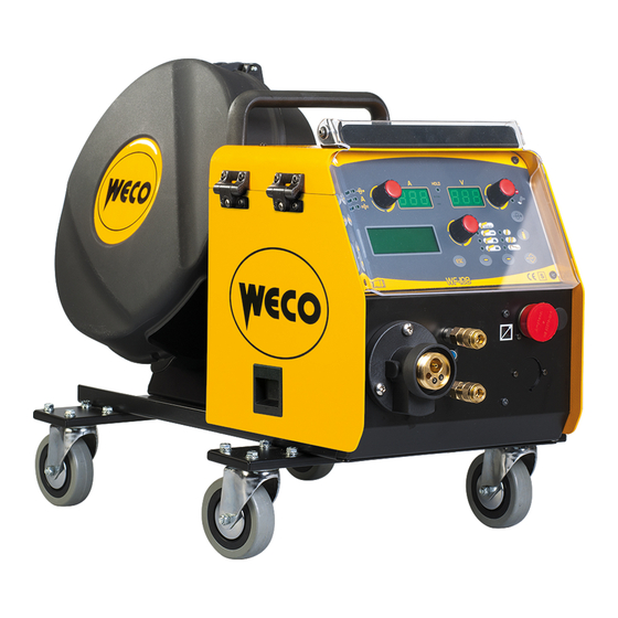
- Page 1 . 006.0001.0940 16/04/2018 V.2.25 WF-104 WF-108 Instruction Manual...
-
Page 2: Table Of Contents
. 006.0001.0940 WF-104 16/04/2018 V.2.25 WF-108 ENGLISH WELD THE WORLD INDEX INTRODUCTION ............................4 PRESENTATION ............................5 INSTALLATION ............................6 FRONT PANEL ............................7 REAR PANEL ............................8 MIG/MAG INSTALLATION ........................9 WIRE SPOOL POSITIONING ......................... 11 POSITIONING THE WIRE IN THE WIRE FEEDER ................12 USER INTERFACE .......................... - Page 3 4T - 3 LEVEL MIG/MAG WELDING ....................... 66 12.8 4T B-LEVEL - 3 LEVEL MIG/MAG WELDING ..................67 TECHNICAL DATA ..........................68 13.1 WF-104 TECHNICAL DATA ........................68 13.2 WF-108 TECHNICAL DATA ........................68 WIRING DIAGRAM ..........................70 14.1 WF-104 WIRING DIAGRAM ........................70 14.2...
-
Page 4: Introduction
. 006.0001.0940 WF-104 16/04/2018 V.2.25 WF-108 ENGLISH WELD THE WORLD INTRODUCTION IMPORTANT! This handbook must be consigned to the user prior to installation and commissioning of the unit. Read the "General prescriptions for use" handbook supplied separately from this manual before install- ing and commissioning the unit. -
Page 5: Presentation
Cod. 006.0001.0940 WF-104 16/04/2018 V.2.25 WF-108 ENGLISH WELD THE WORLD 1.1 PRESENTATION Wire feeder WF-104/WF-108 is designed for connection to a power source for MIG/MAG welding. The welding modes and procedures available are those indicated in the table. MODE PROCEDURE TWO STROKE (2T) TWO SPOT STROKE (2T-SPOT) MANUAL MIG/MAG FOUR STROKE (4T) TWO STROKE (2T) SYNERGIC MIG/MAG TWO SPOT STROKE (2T-SPOT) PULSED SYNERGIC MIG/MAG... -
Page 6: Installation
. 006.0001.0940 WF-104 16/04/2018 V.2.25 WF-108 ENGLISH WELD THE WORLD INSTALLATION DANGER! Lifting and positioning Read the warnings highlighted by the following symbols in the “General prescriptions for use”. 1. Assemble the various units as described in the instruction manual of the power source trolley. 2. Set the welding power source ON/OFF switch to “O” unit switched off). 3. Connect the power source mains supply cable to the mains socket outlet. 4. Secure the cable bundle connectors to the wire feeder. 5. Secure the cable bundle connectors to the welding power source. 6. Connect the power supply cable of the cooling unit to the auxiliary power socket on the power source. -
Page 7: Front Panel
Cod. 006.0001.0940 WF-104 16/04/2018 V.2.25 WF-108 ENGLISH WELD THE WORLD 2.1 FRONT PANEL WF-104 WF-108 1: Remote controller connector. 2: Provision for connection of the push pull torch (purchasing and installing the relative kit). EURO TORCHwelding socket. 4: Connector for coolant hose. Torch → Power source 5: Connector for coolant hose. Power source → Torch 6: Port provided to connect a USB memory stick to export/import JOBs. -
Page 8: Rear Panel
. 006.0001.0940 WF-104 16/04/2018 V.2.25 WF-108 ENGLISH WELD THE WORLD 2.2 REAR PANEL WF-104 WF-108 1: Connector for connection to the programmer. You can update the software of the equipment using the programming kit. 2: Male socket for the connection of the power cable coming from the cable bundle. 3: Gas rear connector. This is for the connection of the gas pipe coming from the cable bundle. 4: Cable bundle signal connector. 5: Connector for coolant hose. Power source → Cooler 6: Connector for coolant hose. Cooler → Power source 7: Port provided to connect a USB memory stick to export/import JOBs. -
Page 9: Mig/Mag Installation
Cod. 006.0001.0940 WF-104 16/04/2018 V.2.25 WF-108 ENGLISH WELD THE WORLD 2.3 MIG/MAG INSTALLATION DANGER! Electric shock hazard! Read the warnings highlighted by the following symbols in the “General prescriptions for use”. WF-104... - Page 10 . 006.0001.0940 WF-104 16/04/2018 V.2.25 WF-108 ENGLISH WELD THE WORLD WF-108...
-
Page 11: Wire Spool Positioning
Cod. 006.0001.0940 WF-104 16/04/2018 V.2.25 WF-108 ENGLISH WELD THE WORLD 2.4 WIRE SPOOL POSITIONING 1. Open the unit side door to gain access to the spool compartment. 2. Unscrew the cap of the spool holder. 3. If necessary, fit an adapter for the wire spool. 4. Fit the spool in the spool holder, ensuring it is located correctly. -
Page 12: Positioning The Wire In The Wire Feeder
. 006.0001.0940 WF-104 16/04/2018 V.2.25 WF-108 ENGLISH WELD THE WORLD 2.5 POSITIONING THE WIRE IN THE WIRE FEEDER Lower the wire feeder pressure devices. 2. Raise the wire feeder pressure arms. 3. Remove the protective cover. 4. Check that the feed rolls are suitable for the wire gauge. § “15.5 WIRE FEEDER ROLLS” • The diameter of the roll groove must be compatible with the diameter of the welding wire. • The roll must be of suitable shape in relation to the composition of the wire material. • The groove must be "U" shaped for soft materials (Aluminium and its alloys, CuSi3). -
Page 13: User Interface
Cod. 006.0001.0940 WF-104 16/04/2018 V.2.25 WF-108 ENGLISH WELD THE WORLD USER INTERFACE WF-104 STOP HOLD m/min MANUAL Menu Menu... -
Page 14: English Wf
. 006.0001.0940 WF-104 16/04/2018 V.2.25 WF-108 ENGLISH WELD THE WORLD WF-108 L6 L7 HOLD m/min S T O P Menu Menu CODE SYMBOL DESCRIPTION illumination shows that the following parameter can be set: WIRE FEED RATE The value appears on the following display: D1 Short-Spray, pulsed and synergic MIG/MAG welding: illumination shows that the following parameter can be set: WELDING CURRENT HOLD function (at welding end): Illuminates to show a value in the following unit of measurement: AMPERES The value appears on the following display: D1 This LED illuminates to show an anomaly in the operating conditions. - Page 15 Cod. 006.0001.0940 WF-104 16/04/2018 V.2.25 WF-108 ENGLISH WELD THE WORLD CODE SYMBOL DESCRIPTION This LED illuminates to show that the following welding mode is selected: MANUAL MIG/MAG This LED illuminates to show that the following welding mode is selected: SYNERGIC MIG/ This LED illuminates to show that the following welding mode is selected: PULSED SYNERGIC MIG/MAG This LED illuminates to show that the following welding mode is selected: DOUBLE PULSED SYNERGIC MIG/MAG Illumination shows that the following function has been activated: 2 stroke procedure § “2T MIG/MAG WELDING” A flashing signal means the following function is activated: 2 stroke procedure § “2T SPOT MIG/MAG WELDING” Illumination shows that the following function has been activated: 4 stroke procedure § “4T MIG/MAG WELDING” / § “4T B-LEVEL MIG/MAG WELDING” Illumination shows that the following function has been activated: 3 levels procedure § “2T - 3 LEVEL MIG/MAG WELDING” / § “2T SPOT - 3 LEVEL MIG/MAG WELDING” / § “4T - 3 LEVEL MIG/MAG WELDING” / § “4T B-LEVEL - 3 LEVEL MIG/MAG WELDING”. During illumination of the following LEDs: The display shows the value of the selected parameter. Welding: The display shows the effective amperes value during welding. HOLD function (at welding end): The display shows the latest measured current value.
-
Page 16: Unit Power-Up
. 006.0001.0940 WF-104 16/04/2018 V.2.25 WF-108 ENGLISH WELD THE WORLD CODE SYMBOL DESCRIPTION Data setting: The encoder adjusts the main welding (and synergy) parameter, shown on the following display: D1 During welding operations with an active JOB: The encoder temporarily modifies the main welding parameter, shown on the following display: D1 Manual MIG/MAG mode: The encoder adjusts the welding voltage, and the relative value is shown, in volts, on the following display: D2 Synergic MIG/MAG mode: The encoder is used to correct the factory-set value of the selected synergic curve, the value of which is shown on the following display: D3 During welding operations with an active JOB: The encoder temporarily modifies the main... -
Page 17: Power Source Management By Remote Control
Cod. 006.0001.0940 WF-104 16/04/2018 V.2.25 WF-108 ENGLISH WELD THE WORLD 4.1 POWER SOURCE MANAGEMENT BY REMOTE CONTROL Hold down the button for 3 seconds. [ OPERATION TO BE PERFORMED ON THE POWER SOURCE USER INTERFACE] The following LED illuminates on the power source panel: The following message appears on the power source displays: - - - The power source is managed by the remote control connected to it. The welding power source sets up for welding. First power-up or power-ups following a RESET procedure The welding power source sets up for welding with the factory preset values.. -
Page 18: Partial Reset
. 006.0001.0940 WF-104 16/04/2018 V.2.25 WF-108 ENGLISH WELD THE WORLD 5.1 PARTIAL RESET The reset procedure involves restoration of the parameter values and settings, except the following settings: - Settings of the SETUP menu. - saved JOBS. Example of control panel (applies to model WF-108) L6 L7 HOLD ACTIVATION m/min S T O P... -
Page 19: Total Reset
Cod. 006.0001.0940 WF-104 16/04/2018 V.2.25 WF-108 ENGLISH WELD THE WORLD 5.2 TOTAL RESET The reset procedure involves complete restoration of the default values, parameters and memory set- tings set in the factory. All memory locations will be reset and hence all your personal welding settings will be lost! Example of control panel (applies to model WF-108) L6 L7 HOLD ACTIVATION m/min S T O P ACTIVATION Menu Menu SETTING OUTPUT ○ Set the welding power source ON/OFF switch to “O” to switch the unit off. ○ Set the welding power source ON/OFF switch to “I” to switch on the unit. ○ Simultaneously press the keys S1... -
Page 20: Set-Up (Initial Set-Up Of The Welding Power Source)
. 006.0001.0940 WF-104 16/04/2018 V.2.25 WF-108 ENGLISH WELD THE WORLD SET-UP (INITIAL SET-UP OF THE WELDING POWER SOURCE) With locked status active it is not possible to access this function. § “LOCKING PROCEDURE”. Example of control panel (applies to model WF-108) L6 L7 HOLD m/min S T O P ACTIVATION Menu Menu SELECTION SETTING OUTPUT SET UP at machine power on ○... - Page 21 Cod. 006.0001.0940 WF-104 16/04/2018 V.2.25 WF-108 ENGLISH WELD THE WORLD NOTE: During the normal operation, the operator can enter the SET UP menu by pressing the key S7 for 5 seconds (SET UP can therefore be accessed with machine on). Tab. 2 - Setup settings MENU SETTING DEFAULT NOTES PAGE ENGLISH ITALIANO FRANÇAIS...
-
Page 22: Operating Hour Counter
. 006.0001.0940 WF-104 16/04/2018 V.2.25 WF-108 ENGLISH WELD THE WORLD Service This setting enables the machine validation (VAL.) and calibration (CALIBRATION) operations. - CURRENT VAL. ○ The validation procedure allows the current value (Ampere) to be correctly detected and displa- yed on the equipment display. The validation procedure requires the equipment to be connected to a suitable static load. - Page 23 Cod. 006.0001.0940 WF-104 16/04/2018 V.2.25 WF-108 ENGLISH WELD THE WORLD Example of control panel (applies to model WF-108) L6 L7 HOLD m/min S T O P ACTIVATION Menu Menu SELECTION SETTING Partial count reset ○ Press and hold down the key S7 for 3 seconds (SET UP with machine on). ○ Press keys S5 and S6 to select line “SET UP 8/8”. ○ Simultaneously hold down keys S5 and S6 for 3 seconds.
-
Page 24: Locking Procedure
. 006.0001.0940 WF-104 16/04/2018 V.2.25 WF-108 ENGLISH WELD THE WORLD 6.2 LOCKING PROCEDURE The procedure inhibits unit adjustments, allowing the user to modify only certain settings depending on the selected lock status. The procedure is used to prevent accidental alteration of the unit settings and welding settings by the operator. Enabling If no locking status is selected (LOCK STATUS = OFF) and if you wish to set up a limitation on use of the welding power source, display page 5/10 of the SETUP menu. Example of control panel (applies to model WF-108) L6 L7 HOLD m/min S T O P CONFIRMATION Menu Menu OUTPUT SETTING SELECTION OUTPUT ○ Use the encoder E3 to select the required lock status. - Page 25 Cod. 006.0001.0940 WF-104 16/04/2018 V.2.25 WF-108 ENGLISH WELD THE WORLD ○ Exit without confirmation - Press the S4 button. This action will automatically close the menu ○ Exit with confirmation - Press the S7 button. The unit restarts with the power-up procedure. The password becomes active. Make a note of the password you set! Tab.
-
Page 26: Gas Flow Adjustment
. 006.0001.0940 WF-104 16/04/2018 V.2.25 WF-108 ENGLISH WELD THE WORLD Example of control panel (applies to model WF-108) L6 L7 HOLD m/min S T O P SELECTION Menu Menu OUTPUT SETTING OUTPUT SETTING ○ Press and hold down the button S7 for 5 second. The SET UP menu will be accessed, with the machine on. LOCK...WRITE PASSWORD : 0000 - The message will appear on display: D4 ○ Enter the active 4 digit numerical password. ○ Use buttons S5 and S6 to select the digit to be changed. -
Page 27: Torch Loading
Cod. 006.0001.0940 WF-104 16/04/2018 V.2.25 WF-108 ENGLISH WELD THE WORLD 6.4 TORCH LOADING WARNING! Make sure the torch in use is correctly sized in relation to the welding current required and for the available and selected cooling type. This prevents the risk of burns to which the operator is potentially exposed, potential faults, and irreversible damage to the torch and the system. - Page 28 . 006.0001.0940 WF-104 16/04/2018 V.2.25 WF-108 ENGLISH WELD THE WORLD CALIBRATION PROCEDURE Example of control panel (applies to model WF-108) L6 L7 HOLD m/min S T O P OUTPUT Menu Menu SETTING OUTPUT SELECTION The welding power source must be on and not set up for welding. The power source remote control must be enabled. and S6 ○ Press and hold down for 3 seconds buttons S5 TOUCH THE WORKPIECE WITH THE GUIDE WIRE TIP AND PRESS THE TORCH...
- Page 29 Cod. 006.0001.0940 WF-104 16/04/2018 V.2.25 WF-108 ENGLISH WELD THE WORLD Example of control panel (applies to model WF-108) L6 L7 HOLD m/min S T O P OUTPUT Menu Menu SETTING SELECTION OUTPUT Calibration carried out correctly CALIBRATION SUCCESSFULLY COMPLETED - The message will appear on display: The calibration value appears on display : D2.
-
Page 30: Alarm Management
. 006.0001.0940 WF-104 16/04/2018 V.2.25 WF-108 ENGLISH WELD THE WORLD ALARM MANAGEMENT This LED illuminates if an incorrect operating condition occurs. An alarm message will appear on display D4. Tab. 4 - Alarm messages MESSAGE MEANING EVENT CHECKS • Make sure that the power re- quired by the welding process is Indicates tripping of the welding lower than the maximum rated power source thermal protection. - Page 31 Cod. 006.0001.0940 WF-104 16/04/2018 V.2.25 WF-108 ENGLISH WELD THE WORLD MESSAGE MEANING EVENT CHECKS • Make sure the IR board is pow- ered on. • Make sure the LEDs on the in- Indicates a CAN communication All functions disabled. terface board go on. problem. WARNING • Check the correct connection Exit the alarm state by performing...
-
Page 32: Parameters Activation
. 006.0001.0940 WF-104 16/04/2018 V.2.25 WF-108 ENGLISH WELD THE WORLD PARAMETERS ACTIVATION The welding parameters are available in accordance with the selected welding mode and procedure. Certain parameters are available only after other parameters or functions of the unit have been enabled or set. The table shows the settings required to enable each parameter. √ : always available. 1: available in HSL line power sources on selecting one of the "PF" curves (e.g.: SG2/SG3 PF) 2: Available selecting one of the "PR" curves (e.g.: SG2/SG3 PR) MODE → MENU PROCEDURE ↓ → PARAMETER ↓ Arc correction in Volts ... -
Page 33: Welding Parameters
Cod. 006.0001.0940 WF-104 16/04/2018 V.2.25 WF-108 ENGLISH WELD THE WORLD 8.1 WELDING PARAMETERS • Arc correction in volts ○ This parameter corrects the synergic voltage value relative to the synergic point of the synergic and pulsed MIG/MAG processes, while it manages correction of the voltage of the high value in the MIG/MAG double pulsed process. ○ The default value for horizontal and frontal welding is 0.0 V. - NOTE: A value >0 produces an increase in the length of the welding arc, while a value <0 pro- duces a shorter arc. - Page 34 . 006.0001.0940 WF-104 16/04/2018 V.2.25 WF-108 ENGLISH WELD THE WORLD - Consequences of a lower value: • More reliable starting. • ARC SET ○ In pulsed synergic welding this parameter directly influences the size of the welding pulses. ○ The value SYN=100 denotes the optimal synergic value chosen by the manufacturer. - IMPORTANT NOTE: This parameter should be adjusted as little as possible. To correct synergy it is advisable to use arc correction by means of the voltage parameter.
- Page 35 Cod. 006.0001.0940 WF-104 16/04/2018 V.2.25 WF-108 ENGLISH WELD THE WORLD • BURN BACK ○ The BURN BAck vAlUe iS ASSOciATed wiTh The qUANTiTy OF wiRe ThAT iS BURNT AT The eNd OF The weld iNg pROcedURe ○ In synergic welding the optimal BURN BACK value (indicated with SYN) varies in general with variations of the synergic parameters. ○ In synergic welding, if the value BURN BACK = SYN is selected the welding power source will always have the optimal BURN BACK value set when the main welding parameter changes.
- Page 36 . 006.0001.0940 WF-104 16/04/2018 V.2.25 WF-108 ENGLISH WELD THE WORLD welding (2nd level). ○ The time is determined by the operator on the basis of the time he presses the torch trigger during the third time. ○ This is helpful to start the weld run with different heat input compared to steady state welding conditions. ○ High values (e.g. 130 %) are generally required by aluminium alloys to create a weld pool. • CRATER 3LEV • Crater in 3 levels operation ○ The parameter adjusts the 3rd level wire feed rate as a percentage of the wire feed rate set for welding (2nd level). ○ The time is determined by the operator on the basis of the time he presses the torch trigger during the third time. ○ This is helpful to finish the weld run with different heat input compared to steady state welding conditions.
- Page 37 Cod. 006.0001.0940 WF-104 16/04/2018 V.2.25 WF-108 ENGLISH WELD THE WORLD Wire speed (m/min) Freq 2puls High speed Middle speed Low speed Cycle 2puls minute • CYCLE 2PULS • Double pulsed duty cycle ○ The parameter adjusts the high feed rate time. ○ The value is expressed as a percentage over the pulse frequency period. • ARC2 2PULS • Arc2 voltage in double pulsed mode ○...
-
Page 38: Characteristics Of The Menu Levels
. 006.0001.0940 WF-104 16/04/2018 V.2.25 WF-108 ENGLISH WELD THE WORLD CHARACTERISTICS OF THE MENU LEVELS 9.1 1ST LEVEL The menu shows the setting of the most important welding parameters (or synergic settings) relative to the selected welding process. Acronym of the selected welding SYN: This code indicates that parameters control is synergic. process. MAN: This code indicates that parameters control is manual. -
Page 39: 3Rd Level
Cod. 006.0001.0940 WF-104 16/04/2018 V.2.25 WF-108 ENGLISH WELD THE WORLD 9.3 3RD LEVEL The menu contains the settings and values that are changed infrequently and are to be set up the first time the unit is powered up. The changed parameters remain saved until the next modification or reset of the unit. § “SET-UP (INITIAL SET-UP OF THE WELDING POWER SOURCE)”. Menu level SET UP x / y x = number of the currently dis- played menu page. y = total number of menu pages. Selected parameter. COOLING TYPE Set value. 10 WELDING SETTINGS 10.1 WELDING CURVES SELECTION SHORT/SPRAY ... - Page 40 . 006.0001.0940 WF-104 16/04/2018 V.2.25 WF-108 ENGLISH WELD THE WORLD HIGH SPEED CURVES: the curves are available in HSL series power sources in the PULSED MIG/ MAG - DOUBLE PULSED MIG/MAG mode. Pulsed HS is a special function in the pulsed MIG/MAG mode, featuring a very short and intense arc, EASILY controlled by the welder. HS pulsed, compared to other high deposition welding systems, al- lows the welder to achieve a comfortable arc without increased stress. These curves differ from the other standard curves because of the acronym HS which is displayed after the reference to the welding wire material. Example: PULSED MODE Ø:1.2 SG2/SG3 GAS: 80% Ar / 20% CO2 JOB : FE55 MARIO HIGH CONTROL CURVES: the curves are available in HSL series power sources in PULSED MIG/ MAG - DOUBLE PULSED MIG/MAG welding mode.
- Page 41 Cod. 006.0001.0940 WF-104 16/04/2018 V.2.25 WF-108 ENGLISH WELD THE WORLD POWER FOCUS CURVES: the curves are available in HSL series power sources in SYNERGIC SHORT SPRAY MIG/MAG welding mode. The difference between a standard MIG MAG and Power Focus is its concentration and pressure.
-
Page 42: Manual Mig/Mag Welding
. 006.0001.0940 WF-104 16/04/2018 V.2.25 WF-108 ENGLISH WELD THE WORLD 10.2 MANUAL MIG/MAG WELDING Welding is of the Short/Spray type. Adjustment of the main welding parameters, wire feed rate and voltage is entirely at the discretion of the operator. The optimal work point must be identified for the required welding type. During a welding operation with an active JOB, it is possible to temporarily change the parameters shown in the displays D1 and D2 with their encoders to test the temporary changes made to the weld- ing operation. At the end of the welding operation (and HOLD is quit) the values of the loaded JOB are reset. When the welding operation is not being carried out and a JOB is active through encoder E3, the JOBs belonging to its sequence can be scrolled. -
Page 43: Manual Mig/Mag Parameters Setting (1St Level): Inductance Setting
Cod. 006.0001.0940 WF-104 16/04/2018 V.2.25 WF-108 ENGLISH WELD THE WORLD Shows the average current meas- Shows the average voltage measured Welding Shows “---“. ured during welding. during welding. Shows the average current Shows the average voltage measured HOLD function measured during the last welding during the last welding procedure per- Shows “---“. (At welding end) procedure performed. formed. 10.2.1 Manual MIG/MAG parameters setting (1st level): inductance setting. ○ Using the encoder E3 , edit the value of the selected parameter The value is saved automatically. -
Page 44: Synergic Mig/Mag Welding
. 006.0001.0940 WF-104 16/04/2018 V.2.25 WF-108 ENGLISH WELD THE WORLD 10.3 SYNERGIC MIG/MAG WELDING Set the welding data (material, wire diameter, gas type), shown on display D4 and just one welding parameter, chosen among wire feed rate, Amperes, and workpiece Thickness, shown on display D1. NOTE: The synergic curves were created with reference to a fillet weld in position PB (horizontal-verti- cal) with 10 mm stick-out (distance from torch to workpiece). In general, the parameter set is the wire feed rate (associated with the deposition of filler material) and the synergic welding power source automatically sets the most suitable welding voltage. Encoder E2 can be adjusted to correct the arc shown on display D3, in order to make minor adjustments in accordance with requirements. During a welding operation with an active JOB, it is possible to temporarily change the parameters shown in the displays D1 and D2 with their encoders to test the temporary changes made to the weld- ing operation. At the end of the welding operation (and HOLD is quit) the values of the loaded JOB are reset. -
Page 45: Synergic Mig/Mag Parameters Setting (1St Level): Synergic Curve Setting
Cod. 006.0001.0940 WF-104 16/04/2018 V.2.25 WF-108 ENGLISH WELD THE WORLD This button serves to select the following welding mode: SYNERGIC MIG/MAG Use this button to select one of the following torch trigger procedures: 2 STROKE 2 STROKE SPOT: The procedure is active when the “SPOT TIME” parameter is set to a value other than “OFF”. 4 STROKE 4 STROKE B-LEVEL: The procedure is active when the “B-LEVEL” parameter is set to a value other than “OFF” 3 LEVEL 2 STROKE 3 LEVEL 2 STROKE SPOT: The procedure is active when the “SPOT TIME” parameter is set to a value other than “OFF”. If the "SPOT TIME" parameter is active in the 3 LEVELS procedure, its value denotes the time for which the main welding current is supplied. 3 LEVEL 4 STROKE 3 LEVEL 4 STROKE B-LEVEL: The procedure is active when the “B-LEVEL” parameter is set to a value other than “OFF” Tab. 7 - Main settings and displays in SYNERGIC MIG/MAG mode... - Page 46 . 006.0001.0940 WF-104 16/04/2018 V.2.25 WF-108 ENGLISH WELD THE WORLD ○ Using the encoder E3 , edit the value of the selected parameter The value is saved automatically. Tab. 8 - 2nd level menu parameters in SYNERGIC MIG/MAG mode POWER SOURCE TYPE PROCE- PARAMETER DEFAULT NOTES DURE...
- Page 47 Cod. 006.0001.0940 WF-104 16/04/2018 V.2.25 WF-108 ENGLISH WELD THE WORLD POWER SOURCE TYPE PROCE- PARAMETER DEFAULT NOTES DURE POWER POWER PULSE PULSE HSL INDUCTANCE (row 1/10) (row 1/11) This parameter is present exclusively PR START (row 1/10) (row 1/11) with POWER ROOT. PRE GAS (row 2/10) (row 2/11) 0.0 s 0.0 s 10.0 s...
-
Page 48: Pulsed Synergic Mig/Mag Welding
. 006.0001.0940 WF-104 16/04/2018 V.2.25 WF-108 ENGLISH WELD THE WORLD 10.4 PULSED SYNERGIC MIG/MAG WELDING Set the welding data (material, wire diameter, gas type), shown on display D4 and just one welding parameter, chosen among wire feed rate, Amperes, and workpiece Thickness, shown on display D1. NOTE: The synergic curves were created with reference to a fillet weld in position PB (horizontal-verti- cal) with 10 mm stick-out (distance from torch to workpiece). In general, the parameter set is the wire feed rate (associated with the deposition of filler material) and the synergic welding power source automatically sets the most suitable welding voltage. Encoder E2 can be adjusted to correct the arc shown on display D3, in order to make minor adjustments in accordance with requirements. During a welding operation with an active JOB, it is possible to temporarily change the parameters shown in the displays D1 and D2 with their encoders to test the temporary changes made to the weld- ing operation. At the end of the welding operation (and HOLD is quit) the values of the loaded JOB are... - Page 49 Cod. 006.0001.0940 WF-104 16/04/2018 V.2.25 WF-108 ENGLISH WELD THE WORLD This button serves to select the following welding mode: PULSED SYNERGIC MIG/MAG Use this button to select one of the following torch trigger procedures: 2 STROKE 2 STROKE SPOT: The procedure is active when the “SPOT TIME” parameter is set to a value other than “OFF”. 4 STROKE 4 STROKE B-LEVEL: The procedure is active when the “B-LEVEL” parameter is set to a value other than “OFF” 3 LEVEL 2 STROKE 3 LEVEL 2 STROKE SPOT: The procedure is active when the “SPOT TIME” parameter is set to a value other than “OFF”. If the "SPOT TIME" parameter is active in the 3 LEVELS procedure, its value denotes the time for which the main welding current is supplied. 3 LEVEL 4 STROKE 3 LEVEL 4 STROKE B-LEVEL: The procedure is active when the “B-LEVEL” parameter is set to a value other than “OFF” Tab. 9 - Main settings and displays in PULSED SYNERGIC MIG/MAG mode...
-
Page 50: Pulsed Synergic Mig/Mag Parameters Setting (1St Level): Synergic Curve Setting
. 006.0001.0940 WF-104 16/04/2018 V.2.25 WF-108 ENGLISH WELD THE WORLD 10.4.1 Pulsed Synergic MIG/MAG parameters setting (1st level): synergic curve setting. ○ Scroll down the list of parameters to be edited by pressing buttons S5 and S6 ○ Using the encoder E3 , edit the value of the selected parameter The value is saved automatically. 10.4.2 Pulsed Synergic MIG/MAG parameters setting (2nd level). - Page 51 Cod. 006.0001.0940 WF-104 16/04/2018 V.2.25 WF-108 ENGLISH WELD THE WORLD ARC SET (row 1/10) PRE GAS (row 2/10) 0.0 s 10.0 s 3 LEVEL 4 STROKE SOFT START (row 3/10) 100 % 4 STROKE B-LEVEL START 3LEV (row 4/10) 10 % 130 % 200 %...
-
Page 52: Double Pulsed Synergic Mig/Mag Welding
. 006.0001.0940 WF-104 16/04/2018 V.2.25 WF-108 ENGLISH WELD THE WORLD 10.5 DOUBLE PULSED SYNERGIC MIG/MAG WELDING Set the welding data (material, wire diameter, gas type), shown on display D4 and just one welding parameter, chosen among wire feed rate, Amperes, and workpiece Thickness, shown on display D1. NOTE: The synergic curves were created with reference to a fillet weld in position PB (horizontal-verti- cal) with 10 mm stick-out (distance from torch to workpiece). In general, the parameter set is the wire feed rate (associated with the deposition of filler material) and the synergic welding power source automatically sets the most suitable welding voltage. Encoder E2 can be adjusted to correct the arc shown on display D3, in order to make minor adjustments in accord- ance with requirements. During a welding operation with an active JOB, it is possible to temporarily change the parameters shown in the displays D1 and D2 with their encoders to test the temporary changes made to the welding operation. At the end of the welding operation (and HOLD is quit) the... -
Page 53: Double Pulsed Synergic Mig/Mag Parameters Setting (1St Level): Synergic Curve Setting
Cod. 006.0001.0940 WF-104 16/04/2018 V.2.25 WF-108 ENGLISH WELD THE WORLD This button serves to select the following welding mode: DOUBLE PULSED SYNERGIC MIG/MAG Use this button to select one of the following torch trigger procedures: 2 STROKE 2 STROKE SPOT: The procedure is active when the “SPOT TIME” parameter is set to a value other than “OFF”. 4 STROKE 4 STROKE B-LEVEL: The procedure is active when the “B-LEVEL” parameter is set to a value other than “OFF” 3 LEVEL 2 STROKE 3 LEVEL 2 STROKE SPOT: The procedure is active when the “SPOT TIME” parameter is set to a value other than “OFF”. If the "SPOT TIME" parameter is active in the 3 LEVELS procedure, its value denotes the time for which the main welding current is supplied. 3 LEVEL 4 STROKE 3 LEVEL 4 STROKE B-LEVEL: The procedure is active when the “B-LEVEL” parameter is set to a value other than “OFF” Tab. 11 - Main settings and displays in DOUBLE PULSED SYNERGIC MIG/MAG mode... - Page 54 . 006.0001.0940 WF-104 16/04/2018 V.2.25 WF-108 ENGLISH WELD THE WORLD ○ Using the encoder E3 , edit the value of the selected parameter The value is saved automatically. Tab. 12 - 2nd level menu parameters in DOUBLE PULSED SYNERGIC MIG/MAG mode PROCEDURE PARAMETER DEFAULT NOTES ARC SET...
- Page 55 Cod. 006.0001.0940 WF-104 16/04/2018 V.2.25 WF-108 ENGLISH WELD THE WORLD ARC SET (row 1/14) PRE GAS (row 2/14) 0.0 s 10.0 s SOFT START (row 3/14) 100 % START 3LEV (row 4/14) 10 % 130 % 200 % SLOPE 3LEV 1 (row 5/14) 0.1 s 0.5 s...
-
Page 56: Jobs Management
. 006.0001.0940 WF-104 16/04/2018 V.2.25 WF-108 ENGLISH WELD THE WORLD JOBS MANAGEMENT Personalised welding settings, or JOBs, can be saved in memory locations and subsequently uploaded. Up to 99 jobs can be saved (j01-j99). The settings of the SETUP menu are not saved. 11.1 SAVING A JOB This function is available when welding mode is not active. Example of control panel (applies to model WF-108) L6 L7 HOLD m/min S T O P Menu Menu ACTIVATION SELECTION SELECTION ○... - Page 57 Cod. 006.0001.0940 WF-104 16/04/2018 V.2.25 WF-108 ENGLISH WELD THE WORLD Example of control panel (applies to model WF-108) L6 L7 HOLD m/min S T O P Menu Menu OUTPUT SELECTION SELECTION OUTPUT Save and keep original ○ Using the encoder E3 , select one of the unoccupied jobs. Exit without confirmation ○ Press the S4 button.
-
Page 58: Naming Jobs
. 006.0001.0940 WF-104 16/04/2018 V.2.25 WF-108 ENGLISH WELD THE WORLD 11.2 NAMING JOBS JOBS can be named and renamed (maximum 9 characters) in the JOB MENU, LOAD, or SAVE. This function is available when welding mode is not active. Example of control panel (applies to model WF-108) L6 L7 HOLD m/min S T O P Menu Menu ACTIVATION SETTING ACTIVATION OUTPUT OUTPUT SETTING SELECTION ○ Hold down button S8 to activate the job menu. -
Page 59: Loading A User Job
Cod. 006.0001.0940 WF-104 16/04/2018 V.2.25 WF-108 ENGLISH WELD THE WORLD Exit without confirmation ○ Press the S4 button. Return to the job menu. ○ Press the S4 button to exit. Exit with confirmation ○ Hold down for 3 seconds button S8 Return to the job menu. ○ Press button S8 again. -
Page 60: Deleting A Job
. 006.0001.0940 WF-104 16/04/2018 V.2.25 WF-108 ENGLISH WELD THE WORLD ○ Use the encoder E3 , to select the LOAD function. ○ Press buttons S5 and S6 to select parameter JOB. The JOB displayed is the one that was most recently used. When there are no saved jobs the following message appears on the bottom line: NO JOB ○ Using the encoder E3 , select one of the jobs displayed. Exit without confirmation ○... -
Page 61: Exporting/Importing Jobs (Through A Usb Memory Stick)
Cod. 006.0001.0940 WF-104 16/04/2018 V.2.25 WF-108 ENGLISH WELD THE WORLD ○ Use the encoder E3 , to select the DELETE function. ○ Press buttons S5 and S6 to select parameter JOB. The JOB displayed is the one that was most recently used. When there are no saved jobs the following message appears on the bottom line: NO JOB ○ Using the encoder E3 , select one of the jobs displayed. Exit without confirmation ○... -
Page 62: Exporting A Job
. 006.0001.0940 WF-104 16/04/2018 V.2.25 WF-108 ENGLISH WELD THE WORLD 11.6 EXPORTING A JOB Example of control panel (applies to model WF-108) L6 L7 HOLD m/min S T O P Menu Menu SELECTION ACTIVATION SELECTION OUTPUT ○ Insert the memory stick in the USB port. ○ Hold down button S8 to activate the job menu. -
Page 63: Importing A Job
Cod. 006.0001.0940 WF-104 16/04/2018 V.2.25 WF-108 ENGLISH WELD THE WORLD The JOBs saved on the panel EXPORT IN PROGRESS are being exported Exporting procedure comple- EXPORT COMPLETE 11.7 IMPORTING A JOB Example of control panel (applies to model WF-108) L6 L7 HOLD m/min S T O P Menu Menu ACTIVATION SELECTION... -
Page 64: Selecting Jobs Using The Torch Buttons
. 006.0001.0940 WF-104 16/04/2018 V.2.25 WF-108 ENGLISH WELD THE WORLD Tab. 14 - JOB importing operation messages MESSAGE MEANING CHECKS - incorrectly inserted memory stick USB DEVICE NOT FOUND USB device not found - memory stick removed before completing the operation. - there are no JOBs loaded onto the USB... -
Page 65: Torch Trigger Modes
Cod. 006.0001.0940 WF-104 16/04/2018 V.2.25 WF-108 ENGLISH WELD THE WORLD 12 TORCH TRIGGER MODES 12.1 2T MIG/MAG WELDING 1. Bring the torch up to the workpiece. 2. Press (1T) and keep the torch trigger pressed. The wire advances at the approach speed until making contact with the material. If the arc does not strike after 10 cm wire protrusion, wire feeding is locked and the welding unit outputs are de- energized. The arc strikes and the wire feeder accelerates to the set feed rate value. 3. Release (2T) trigger to start the weld completion procedure. Gas flow continues for the time set in the post gas parameter (adjustable time). 12.2 2T SPOT MIG/MAG WELDING 1. Bring the torch up to the workpiece. -
Page 66: Level Mig/Mag Welding
. 006.0001.0940 WF-104 16/04/2018 V.2.25 WF-108 ENGLISH WELD THE WORLD When the trigger is pressed and released immediately, the system returns to the welding current. 3. Press (3T) trigger and keep it pressed to start the weld completion procedure. Gas flow continues until the torch trigger is released. 4. Release (4T) torch trigger to start the post gas procedure (adjustable time). 12.5 2T - 3 LEVEL MIG/MAG WELDING 1. Bring the torch up to the workpiece. 2. Press (1T) torch trigger. -
Page 67: B-Level - 3 Level Mig/Mag Welding
Cod. 006.0001.0940 WF-104 16/04/2018 V.2.25 WF-108 ENGLISH WELD THE WORLD 5. Release the torch trigger a second time (4T) to close the weld and run the post gas procedure. 12.8 4T B-LEVEL - 3 LEVEL MIG/MAG WELDING The welding process is the same as the 4T - 3 LEVELS process except that during normal speed welding pressing and immediately releasing the torch trigger switches the unit to the second weld- ing current. The trigger must not be pressed for more than 0.3 seconds; otherwise, the weld completion stage will start. When the trigger is pressed and released immediately, the system returns to the welding current. 1. Press (3T) trigger and keep it pressed to start the crater filler procedure. The weld is closed in the same way as with the 4T - 3 LEVELS process. -
Page 68: Technical Data
. 006.0001.0940 WF-104 16/04/2018 V.2.25 WF-108 ENGLISH WELD THE WORLD 13 TECHNICAL DATA 13.1 WF-104 TECHNICAL DATA Model WF-104 EN 60974-5 Construction standards EN 60974-10 Class A Supply voltage 48 V a.c. Dimensions ( L x D x H ) 245 x 670 x 470 mm Weight 21.5 kg Protection rating IP23... - Page 69 Cod. 006.0001.0940 WF-104 16/04/2018 V.2.25 WF-108 ENGLISH WELD THE WORLD...
-
Page 70: Wiring Diagram
. 006.0001.0940 WF-104 16/04/2018 V.2.25 WF-108 ENGLISH WELD THE WORLD 14 WIRING DIAGRAM 14.1 WF-104 WIRING DIAGRAM +34V-REM 3 4 5 9 101112 14 16 19202122 23 25262728 2930 3132 9 101112 1516 19 21 20 22 23 25 2728... - Page 71 Cod. 006.0001.0940 WF-104 16/04/2018 V.2.25 WF-108 ENGLISH WELD THE WORLD 3 4 5 9 101112 14 16 19202122 23 25262728 2930 3132 9 101112 1516 19 21 20 22 23 25 2728 2930 3132...
- Page 72 . 006.0001.0940 WF-104 16/04/2018 V.2.25 WF-108 ENGLISH WELD THE WORLD +34V-REM 3 4 5 9 101112 14 16 19202122 23 25262728 2930 3132...
- Page 73 Cod. 006.0001.0940 WF-104 16/04/2018 V.2.25 WF-108 ENGLISH WELD THE WORLD 3 4 5 9 101112 14 16 19202122 23 25262728 2930 3132 9 101112 1516 19 21 20 22 23 25 2728 2930 3132...
- Page 74 . 006.0001.0940 WF-104 16/04/2018 V.2.25 WF-108 ENGLISH WELD THE WORLD +34V-REM 3 4 5 9 101112 14 16 19202122 23 25262728 2930 3132...
-
Page 75: Wf-108 Wiring Diagram
Cod. 006.0001.0940 WF-104 16/04/2018 V.2.25 WF-108 ENGLISH WELD THE WORLD 14.2 WF-108 WIRING DIAGRAM +34V-REM 12 13 20 21 33 34... - Page 76 . 006.0001.0940 WF-104 16/04/2018 V.2.25 WF-108 ENGLISH WELD THE WORLD 12 13 20 21 33 34...
- Page 77 Cod. 006.0001.0940 WF-104 16/04/2018 V.2.25 WF-108 ENGLISH WELD THE WORLD +34V-REM...
- Page 78 . 006.0001.0940 WF-104 16/04/2018 V.2.25 WF-108 ENGLISH WELD THE WORLD 12 13 20 21 33 34...
- Page 79 Cod. 006.0001.0940 WF-104 16/04/2018 V.2.25 WF-108 ENGLISH WELD THE WORLD +34V-REM +34V-REM 14 15...
-
Page 80: Power Source → Wf-104
. 006.0001.0940 WF-104 16/04/2018 V.2.25 WF-108 ENGLISH WELD THE WORLD 14.3 POWER SOURCE → WF-104 14.4 REMOTE CONTROL CONNECTOR (back panel) Name Voltage Input/Output +5 V 5 V d.c. B AN2 (5 V) 0-5 V C AN1 (5 V) 0-5 V... -
Page 81: Rc03: Wiring Diagram
Cod. 006.0001.0940 WF-104 16/04/2018 V.2.25 WF-108 ENGLISH WELD THE WORLD 14.4.1 RC03: Wiring diagram 14.4.2 RC04: Wiring diagram Potenziometro 10 kOhm - 100 kOhm Potenziometro 10 kOhm - 100 kOhm 10 kOhm - 100 kOhm potentiometer 10 kOhm - 100 kOhm potentiometer 14.4.3 RC05: Wiring diagram... -
Page 82: Spares
. 006.0001.0940 WF-104 16/04/2018 V.2.25 WF-108 ENGLISH WELD THE WORLD 15 SPARES 15.1 WF-104... - Page 83 Cod. 006.0001.0940 WF-104 16/04/2018 V.2.25 WF-108 ENGLISH WELD THE WORLD No. CODE DESCRIPTION 014.0002.0010 KNOB 014.0002.0002 KNOB 013.0020.0101 FRONT PANEL LABEL 013.0000.8010 LOGIC BOARD PLATE 016.0011.0001 CAP Ø=10 050.5315.0000 COMPLETE LOGIC FRONT PANEL 012.0001.0500 FRONT PLASTIC PANEL 011.0014.0051 FRONT PLATE 011.0014.0066...
- Page 84 . 006.0001.0940 WF-104 16/04/2018 V.2.25 WF-108 ENGLISH WELD THE WORLD 15.2 WF-108...
- Page 85 Cod. 006.0001.0940 WF-104 16/04/2018 V.2.25 WF-108 ENGLISH WELD THE WORLD No. CODE DESCRIPTION 014.0002.0002 KNOB 013.0020.0801 FRONT PANEL LABEL 050.5325.0000 COMPLETE LOGIC FRONT PANEL 018.0002.0004 QUICK CLUTCH 017.0003.0055 NIPPLE CONNECTOR 021.0001.2004 PLASTIC HOUSING 011.0014.0001 FRONT PLATE 021.0001.2022 CAPILLARY TUBE 021.0001.2000 COUPLING EURO 021.0001.2017...
- Page 86 . 006.0001.0940 WF-104 16/04/2018 V.2.25 WF-108 ENGLISH WELD THE WORLD KIT WF-108...
- Page 87 Cod. 006.0001.0940 WF-104 16/04/2018 V.2.25 WF-108 ENGLISH WELD THE WORLD No. CODE DESCRIPTION 011.0014.0023 SUPPORT PLATE 004.0000.0210 WF SUPPORT KIT 011.0014.0009 WHEEL PLATE 004.0001.0007 WHEEL 010.0000.0012 WHEEL KIT 011.0014.0012 SLIDE METAL PLATE 010.0000.0013 SLIDING KIT...
-
Page 88: Wire Feeder Motor
. 006.0001.0940 WF-104 16/04/2018 V.2.25 WF-108 ENGLISH WELD THE WORLD 15.3 WIRE FEEDER MOTOR... - Page 89 Cod. 006.0001.0940 WF-104 16/04/2018 V.2.25 WF-108 ENGLISH WELD THE WORLD No. CODE DESCRIPTION 002.0000.0254 MOTOR COIL 002.0000.0308 DISTANCE RING 002.0000.0306 COUNTERSUNK SCREW M6x12 002.0000.0307 SCREW M6x20 002.0000.0295 WIRE FEEDER SUPPORT 002.0000.0318 SCREW M4x8 002.0000.0291 INSULATIONMOTOR KIT 002.0000.0300 MAIN GEAR DRIVE 002.0000.0298 SHAFT 002.0000.0299 GEAR ADAPTOR FEED ROLL (BRONZE BUSHING) 002.0000.0309...
-
Page 90: Wire Feeder Rolls
. 006.0001.0940 WF-104 16/04/2018 V.2.25 WF-108 ENGLISH WELD THE WORLD 15.4 WIRE FEEDER ROLLS Standard CODE Ø WIRE TYPE Ø ROLL GROOVE 002.0000.0140 0.6-0.8 002.0000.0141 0.8-1.0 V groove D=37x12/d=19 V 35° V Solid wire 002.0000.0142 1.0-1.2 002.0000.0143 1.2-1.6 002.0000.0144 0.6-0.8 002.0000.0145 1.0-1.2 U shape 002.0000.0146... - Page 91 Cod. 006.0001.0940 WF-104 16/04/2018 V.2.25 WF-108 ENGLISH WELD THE WORLD Double driving roll (4 roll with groove) - RECOMMENDED CONFIGURATION CODE Ø WIRE Ø ROLL 002.0000.0168 1.0-1.2 D=37x12/d=19 U DOUBLE D. 002.0000.0169 1.2-1.6 D=37x12/d=19 U DOUBLE D. 002.0000.0171 1.0-1.2 D=37x12/d=19 UT TEFLON. 002.0000.0172 1.2-1.6 D=37x12/d=19 UT TEFLON GEAR ADAPTOR FEED ROLL 002.0000.0299...
- Page 92 . 006.0001.0940 WF-104 16/04/2018 V.2.25 WF-108 ENGLISH WELD THE WORLD Double driving roll (2 roll with groove + 2 flat roll) CODE Ø WIRE Ø ROLL 002.0000.0168 1.0-1.2 D=37x12/d=19 U DOUBLE D. 002.0000.0169 1.2-1.6 D=37x12/d=19 U DOUBLE D. 002.0000.0171 1.0-1.2 D=37x12/d=19 UT TEFLON. 002.0000.0172 1.2-1.6 D=37x12/d=19 UT TEFLON GEAR ADAPTOR FEED ROLL 002.0000.0299...
- Page 93 Cod. 006.0001.0940 WF-104 16/04/2018 V.2.25 WF-108 ENGLISH WELD THE WORLD Transformation KIT from STANDARD wire feeder to Double driving roll wire feeder Transformation KIT from STANDARD wire feeder to Double driving roll wire feeder Standard Standard Double driving roll Double driving roll...
- Page 94 . 006.0001.0940 WF-104 16/04/2018 V.2.25 WF-108 ENGLISH WELD THE WORLD...
- Page 95 Cod. 006.0001.0940 WF-104 16/04/2018 V.2.25 WF-108 ENGLISH WELD THE WORLD...
- Page 96 . 006.0001.0940 16/04/2018 V.2.25 WECO srl Via S. Antonio 22 - Loc. Belvedere 36056 Tezze sul Brenta (Vicenza) - Italy Tel +39 0424 561 943 - fax +39 0424 561 944 www.weco.it...
Need help?
Do you have a question about the WF-104 and is the answer not in the manual?
Questions and answers