
Subscribe to Our Youtube Channel
Related Manuals for Weco WF-107


Summary of Contents for Weco WF-107
- Page 1 Cod.006.0001.1260 10/07/2017 v2.14 ENGLISH WECO srl Via S. Antonio, 22 - BELVEDERE 36056 TEZZE SUL BRENTA (VICENZA) ITALY Tel.+39 0424 561943 – Fax +39 0424 561944 www.weco.it - E-mail info@weco.it WF-107 Instruction manual...
- Page 2 Cod.006.0001.1260 10/07/2017 v2.14 WF-107 ENGLISH 2/32...
-
Page 3: Table Of Contents
USER INTERFACE ............. 8 16.1 WF-107 ................27 UNIT POWER-UP..............9 16.2 CAVO 320 MSR→WF-107 ..........28 SOFTWARE COMPATIBILITY BETWEEN THE DEVICES ... 9 16.3 REMOTE CONTROLLER ........... 29 RESET (LOAD FACTORY SETTINGS) ......10 16.3.1 RC03: ELECTRICAL DIAGRAM............ 29 TOTAL RESET .............. -
Page 4: Introduction
This symbol identifies a reference to a chapter of the manual. This symbol accompanies important information concerning the execution of the relevant operations. Wire feeder WF-107 is designed for connection to a power source for MIG/MAG welding. The welding modes and procedures available are those indicated in the table. -
Page 5: Installation
Cod.006.0001.1260 WF-107 10/07/2017 v2.14 ENGLISH INSTALLATION 6. Connect the MIG/MAG torch coolant outlet and return hoses to the coolant fittings on the wire feeder. 7. Connect the MIG/MAG torch coolant outlet and return hoses of WARNING! the cable bunch to the fittings on the cooling unit and on the wire Lifting and positioning feeder. -
Page 6: Wire Spool Positioning
Cod.006.0001.1260 10/07/2017 v2.14 WF-107 ENGLISH WIRE SPOOL POSITIONING POSITIONING THE WIRE IN THE WIRE FEEDER 1. Open the unit side door to gain access to the spool compartment. 1. Lower the wire feeder pressure devices. 2. Unscrew the cap of the spool holder. - Page 7 Cod.006.0001.1260 WF-107 10/07/2017 v2.14 ENGLISH 9. Refit the protective cover. 10. Set the welding power source ON/OFF switch to “I” (unit powered). 11. Feed the wire through the torch until it protrudes from the tip, pressing button on the unit front panel.
-
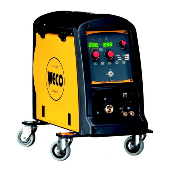
Page 8: User Interface
Cod.006.0001.1260 10/07/2017 v2.14 WF-107 ENGLISH USER INTERFACE CODE SYMBOL DESCRIPTION When this LED illuminates the following parameter can be set: WIRE FEED RATE The value appears on the following display: D1 When this LED illuminates the following parameter can be set: WELDING CURRENT The value appears on the following display: D1 This LED illuminates to show an anomaly in the operating conditions. -
Page 9: Unit Power-Up
The welding power source sets up for welding in the latest stable welding configuration that was active at the time of power-off. SOFTWARE COMPATIBILITY BETWEEN THE DEVICES Depending on the software versions of the power source and the WF-107 unit, situations of incompatibility between the units may occur. The table shows the circumstances wherein incompatibility may occur and the relative consequences. -
Page 10: Reset (Load Factory Settings)
Cod.006.0001.1260 10/07/2017 v2.14 WF-107 ENGLISH RESET (LOAD FACTORY SETTINGS) The reset procedure involves complete restoration of the default values, parameters and memory settings set in the factory. Too many changes made to the welding parameters so user finds it difficult to restore defaults. -
Page 11: Set-Up (Initial Set-Up Of The Welding Power Source)
Cod.006.0001.1260 WF-107 10/07/2017 v2.14 ENGLISH SET-UP (INITIAL SET-UP OF THE WELDING POWER SOURCE) With locked status active it is not possible to access this function. § 8.1 LOCKING PROCEDURE Set the welding power source ON/OFF switch to “O” to switch the unit off. -
Page 12: Locking Procedure
Cod.006.0001.1260 10/07/2017 v2.14 WF-107 ENGLISH LOCKING PROCEDURE The procedure inhibits unit adjustments, allowing the user to modify only certain settings depending on the selected lock status. The procedure is used to prevent accidental alteration of the unit settings and welding settings by the operator. -
Page 13: Torch Loading
Err. C12 the following actions: Switch the power source off. Software Incompatibility Alarm All functions disabled. It triggers when the WF-107 software Exceptions: - In this event, update the software of the power Err. C69 release is incompatible with the power - cooling fan. -
Page 14: Al. Cur.
Cod.006.0001.1260 10/07/2017 v2.14 WF-107 ENGLISH All functions disabled. Exceptions: - cooling fan. An audible signal will sound (buzzer). Overcurrent alarm - Check that the programmed arc voltage value Muting the audible signal: AL. Cur. Indicates tripping of the welding power is not too high in relation to the thickness of the - in torch trigger procedure 2T, release the torch trigger. -
Page 15: Welding Parameters
Cod.006.0001.1260 WF-107 10/07/2017 v2.14 ENGLISH In Synergic welding the optimal soft start value (indicated with SYN) WELDING PARAMETERS varies in general with variations of the synergic parameters. In Synergic welding, if the value soft start = SYN is selected the... -
Page 16: Parameters Activation
Cod.006.0001.1260 10/07/2017 v2.14 WF-107 ENGLISH 10.1 PARAMETERS ACTIVATION The welding parameters are available in accordance with the selected welding mode and procedure. Certain parameters are available only after other parameters or functions of the unit have been enabled or set. -
Page 17: Welding Settings
Cod.006.0001.1260 WF-107 10/07/2017 v2.14 ENGLISH WELDING SETTINGS 11.1 MIG/MAG WELDING Use this button to select one of the following welding modes: MIG/MAG INTERVAL MIG/MAG CONTINUOUS MIG/MAG SPOT WELDIG WELDING Use this button to select one of the following torch trigger procedures:... -
Page 18: Mig/Mag Parameters Setting (2Nd Level)
Cod.006.0001.1260 10/07/2017 v2.14 WF-107 ENGLISH 11.1.2 MIG/MAG PARAMETERS SETTING (2ND LEVEL) Hold down the button for 3 seconds to gain access to the 2nd level menu. The acronym relative to the setting to be edited appears on the following displays: D1 The value relative to the selected setting appears on the following displays: D2 Use the encoder to scroll the list of settings to edit. -
Page 19: Jobs Management
Cod.006.0001.1260 WF-107 10/07/2017 v2.14 ENGLISH JOBS MANAGEMENT Personalised welding settings, or JOBs, can be saved in memory locations and subsequently uploaded. Up to 99 jobs can be saved (j01-j99). The settings of the SETUP menu are not saved. 12.1 SAVING A JOB This function is available when welding mode is not active. -
Page 20: Torch Trigger Modes
Cod.006.0001.1260 10/07/2017 v2.14 WF-107 ENGLISH Exit with confirmation Press the button. This action will automatically close the menu. TORCH TRIGGER MODES 13.1 2T MIG/MAG WELDING 1. Bring the torch up to the workpiece. 2. Press (1T) and keep the torch trigger pressed. -
Page 21: Technical Data
Cod.006.0001.1260 WF-107 10/07/2017 v2.14 ENGLISH TECHNICAL DATA Model WF-107 EN 60974-5 Construction standards EN 60974-10 Class A Supply voltage 48 V a.c. Dimensions ( L x D x H ) 245 x 670 x 470 mm Weight 21.5 kg Protection rating... -
Page 22: Spare Parts
Cod.006.0001.1260 10/07/2017 v2.14 WF-107 ENGLISH SPARE PARTS 15.1 WF-107 22/32... - Page 23 Cod.006.0001.1260 WF-107 10/07/2017 v2.14 ENGLISH N° CODE DESCRIPTION 040.0001.0151 022.0002.0126 KEY CABLE 014.0002.0010 KNOB 014.0002.0008 KNOB WITH POINTER 016.0011.0001 CAP Ø=10 013.0000.8016 LOGIC BOARD PLATE 012.0001.0500 FRONT PLASTIC PANEL 011.0014.0051 FRONT PLATE 011.0014.0066 HANDLE FIXING PLATE 010.0008.0003 WIRE FEEDER MOTOR 011.0006.0007...
-
Page 24: Wire Feeder Motor
Cod.006.0001.1260 10/07/2017 v2.14 WF-107 ENGLISH 15.2 WIRE FEEDER MOTOR 24/32... - Page 25 Cod.006.0001.1260 WF-107 10/07/2017 v2.14 ENGLISH N° CODE DESCRIPTION 002.0000.0254 MOTOR COIL 002.0000.0308 SPACER RING 002.0000.0306 COUNTERSUNK SCREW M6x12 002.0000.0307 SCREW M6x20 002.0000.0295 FEED PLATE 002.0000.0318 SCREW M4x8 002.0000.0291 INSULATION MOUNTING KIT 002.0000.0300 MAIN GEAR DRIVE 002.0000.0298 SHAFT 002.0000.0299 GEAR ADAPTOR FEED ROLL (BRONZE BUSHING) 002.0000.0309...
-
Page 26: Wire Feeder Rolls
Cod.006.0001.1260 10/07/2017 v2.14 WF-107 ENGLISH 15.3 WIRE FEEDER ROLLS 15.3.1 STANDARD D = 37mm d = 19mm N° CODE WIRE DIAMETER GROOVE TYPE 002.0000.0140 0.6-0.8 002.0000.0141 0.8-1.0 V groove Solid wire 002.0000.0142 1.0-1.2 002.0000.0143 1.2-1.6 002.0000.0149 1.0-1.2 002.0000.0150 1.2-1.6 VK shape 002.0000.0151... -
Page 27: Electrical Diagram
Cod.006.0001.1260 WF-107 10/07/2017 v2.14 ENGLISH ELECTRICAL DIAGRAM 16.1 WF-107 27/32... -
Page 28: Cavo 320 Msr→Wf-107
Cod.006.0001.1260 10/07/2017 v2.14 WF-107 ENGLISH 16.2 CAVO 320 MSR→WF-107 28/32... -
Page 29: Remote Controller
Cod.006.0001.1260 WF-107 10/07/2017 v2.14 ENGLISH 16.3 REMOTE CONTROLLER 16.3.1 RC03: ELECTRICAL DIAGRAM Pin Name Voltage Input/Output +5 V 5V d.c. 10 kOhm - 100 kOhm potentiometer B AN2 (5 V) 0-5 V a.c. C AN1 (5 V) 0-5 V a.c. -
Page 30: Rc05: Electrical Diagram
Cod.006.0001.1260 10/07/2017 v2.14 WF-107 ENGLISH 16.3.3 RC05: ELECTRICAL DIAGRAM 16.4 PUSH PULL (OPTIONAL) Name Voltage 16.3.4 RC06: ELECTRICAL DIAGRAM 42 V d.c. 30/32... - Page 31 Cod.006.0001.1260 WF-107 10/07/2017 v2.14 ENGLISH 31/32...
- Page 32 Cod.006.0001.1260 10/07/2017 v2.14 WF-107 ENGLISH 32/32...
Need help?
Do you have a question about the WF-107 and is the answer not in the manual?
Questions and answers