
Related Manuals for PIONEER DJ Toraiz Squid


Summary of Contents for PIONEER DJ Toraiz Squid
- Page 1 Operating Instructions Multitrack Sequencer pioneerdj.com/support/ For FAQs and other support information for this product, visit the above site.
-
Page 2: How To Read This Manual
How to read this manual Thank you for purchasing this Pioneer DJ product. Be sure to read this manual and the “Operating Instructions (Quick Start Guide)” included with this unit. Both documents include important information that you should understand before using this product. -
Page 3: Table Of Contents
Contents How to read this manual ............... 2 Before starting................6 Features..................6 Auto power off function ..............7 Part names and functions ............8 Control panel ................8 Rear panel .................. 16 Connections................18 Connecting inputs and outputs ........... 19 The data structure of the unit.......... - Page 4 Contents CV SLIDE mode ................. 65 ACTIVE mode................66 INTERPOLATION............... 67 RANDOMIZER................70 HARMONIZER................71 COPY/PASTE................73 DELETE..................75 STEP SHIFT ................78 STEP JUMP................78 FIXED LENGTH................79 Phrase arrangement section ..........80 SPEED MODULATION function ..........80 MELODIC CONTROL function ........... 86 GROOVE CONTROL function............
- Page 5 Contents Connecting to external equipment ........152 Connecting the unit to an external MIDI device or a PC/Mac to play ................... 152 Synchronizing the unit to external MIDI devices or a PC/Mac ....................156 Connecting the unit to an external CV/GATE compatible device to play................
-
Page 6: Before Starting
Before starting Features The SQUID is a standalone multitrack sequencer that can connect various music production equipment and produce phrases successively. Phrases can be sequenced quickly using the step parameter knobs which work independently for each parameter and the sequence functions such as HARMONIZER and INTERPOLATION. -
Page 7: Auto Power Off Function
Before starting Auto power off function This unit comes with an auto power off function, which is enabled as the default setting. The power turns off automatically when there is no signal input, output or operation for approximately 4 hours. To turn on the power once the unit has turned off automatically, press the [] button on the rear panel to release it to the off position (), and then press in the [] button again (). -
Page 8: Part Names And Functions
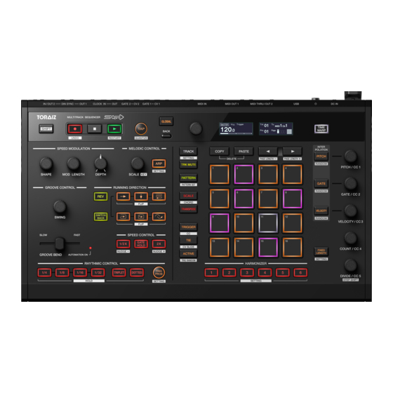
Part names and functions Control panel 1 Global section 2 Phrase arrangement section 3 Step edit section... - Page 9 Part names and functions Global section 1 SHIFT button When operating a button or knob while holding down the [SHIFT] button, you can access an alternative function. 2 (record) button Toggles the pad performance, Harmonizer performance, and Real-time recording state of the automation information. For details, refer to “Real-time recording”...
- Page 10 Part names and functions 5 TAP button Sets the BPM of a sequence. Flashes to BPM during the sequence playback. For details, refer to “Setting the BPM (Beats Per Minute) of a sequence” (page 28). [SHIFT] + press: Switches the display to QUANTIZE setting. For details, refer to “QUANTIZE settings”...
- Page 11 Part names and functions Phrase arrangement section b SHAPE knob c MOD LENGTH knob d DEPTH knob b to d: Performs various operations for the Speed Modulation function. For details, refer to “SPEED MODULATION function” (page 80). e SCALE knob f ARP button e &...
- Page 12 Part names and functions g SWING knob h GROOVE BEND slider i AUTOMATION ON indicator g to i: Used to perform various operations for the Groove Control function. For details, refer to “GROOVE CONTROL function” (page 92). j REV button (right) button (down) button (zigzag) button...
- Page 13 Part names and functions Step edit section w TRACK button x TRK MUTE button y PATTERN button z SCALE button A TRANSPOSE button B TRIGGER button C TIE button D ACTIVE button w to D: Switches the 16-pad function when each button is pressed. For details, refer to “Switching the 16-pad mode”...
- Page 14 Part names and functions E COPY button F PASTE button E & F: Used to copy and paste specific information such as steps, patterns, pattern sets, and notes. Pressing both buttons at the same time enables deleting mode. For details, refer to “COPY/PASTE” (page 73) and “DELETE” (page 75).
- Page 15 Part names and functions O PITCH/CC 1 knob P GATE/CC 2 knob Q VELOCITY/CC 3 knob R COUNT/CC 4 knob S DIVIDE/CC 5 knob O to S: Used to change parameters of a note and step. For details, refer to “TRIGGER mode”...
-
Page 16: Rear Panel
Part names and functions Rear panel 1 2 3 4 1 Cable hook Hook the AC adapter cable when using this unit. Refer to “How to use the cable hook” (page 20). 2 DC IN terminal Connect the AC adapter cable. 3 ... - Page 17 Part names and functions 8 CV OUT1 terminal Connect to a device that receives CV signals from this unit. 9 GATE OUT1 terminal Connect to a device that receives GATE signals from this unit. a CV OUT2 terminal Connect to a device that receives CV signals from this unit. b GATE OUT2 terminal Connect to a device that receives GATE signals from this unit.
-
Page 18: Connections
Connections • Be sure to turn off the power, disconnect the USB cable from this unit, and unplug the power cord from the power outlet whenever making or changing connections. • Connect the power cord and a USB cable once all the connections between devices have been completed. -
Page 19: Connecting Inputs And Outputs
Connections Connecting inputs and outputs 1 MIDI-compatible Synthesizer, Drum machine, Sound module, etc. 2 MIDI-compatible Synthesizer, Drum machine, Sound module, MIDI keyboard, etc. 3 DIN SYNC-compatible Synthesizer, Drum machine, Sound module, etc. 4 PC/Mac 5 CV/GATE/CLOCK-compatible Synthesizer, Drum machine, Sound module, etc. 6 AC adaptor (included) 7 Power cord (included) 8 To power outlet... - Page 20 Connections How to use the cable hook Hook the connection cable of the AC adaptor to avoid accidentally disconnecting it from the unit. 1 Fit the connection cable of the AC adaptor into the cable hook. 2 Connect the plug of the connection cable to the [DC IN] terminal (1). If the cable on the left side of the cable hook is too long, tighten it moderately (2).
-
Page 21: The Data Structure Of The Unit
The data structure of the unit The data structure of the unit is as shown below. Project: A project is a unit of work created by the user containing various information. One project consists of 16 tracks. Track: Each track can create up to 64 patterns. You can assign a track to a sound source such as track 1 to the drums, track 2 to the bass, track 3 to the synthesizer, etc. -
Page 22: Basic Operation
Basic Operation Project management Creating a new project 1 Press the [GLOBAL] button. The button lights up and you enter the GLOBAL menu. 2 Turn the rotary selector to select [Create New] and press it. 3 Turn the rotary selector to select [OK] and press it. A new project is created. - Page 23 Basic Operation Loading a project 1 Press the [GLOBAL] button. The button lights up and you enter the GLOBAL menu. 2 Turn the rotary selector to select [Open(recent)], [Open(by creation)] or [Open(by name)] and press it. • Select [Open(recent)] to scroll though the projects in the order they were opened.
- Page 24 Basic Operation Naming and saving a project 1 Press the [GLOBAL] button. The button lights up and you enter the GLOBAL menu. 2 Turn the rotary selector to select [Save As] and press it. • Select [Save] to overwrite a project. 3 Press the []/[] button to move the cursor and turn the rotary selector to change the character.
- Page 25 Basic Operation Changing and overwriting a project name 1 Press the [GLOBAL] button. The button lights up and you enter the GLOBAL menu. 2 Turn the rotary selector to select [Rename & Save] and press it. 3 Press the []/[] button to move the cursor and turn the rotary selector to change the character.
-
Page 26: Transport
Basic Operation Transport This chapter explains the functions using buttons and knobs in the Global section (page 9). Playing a sequence 1 Press the [] (play) button. The button lights up in green and a sequence is played. The 16-pads light up depending on the direction of the step movement and the step state which is set through various pad modes. - Page 27 Basic Operation Recording the performance information into a sequence in real time (Real-time recording) The information of the pad performance, the Harmonizer performance, and the automation can be recorded into a sequence. 1 Press the [] (record) button. The button lights up in red and recording standby mode is enabled. 2 Press the [] (play) button.
- Page 28 Basic Operation Setting the BPM (Beats Per Minute) of a sequence The BPM can be set in the following method: • Setting the BPM with a numerical value • Setting the BPM by tapping the [TAP] button Setting the BPM with a numerical value 1 Press the [TAP] button.
-
Page 29: Step Edit Section
Step edit section Switching the 16-pad mode You can switch the functions (the modes) of the 16-pads as needed. • Track mode (page 31): Selects a track (current track) to operate or edit from the 16 tracks. • Track Mute mode (page 33): You can toggle muting and solo of the 16 tracks. - Page 30 Step edit section • CV Slide mode (page 65): You can set CV Slide for each step where the pitch is changed forward to the next step (pad) smoothly for each step. This function is enabled only when the output terminal of the track is set to [CV/GATE1] or [CV/GATE2].
-
Page 31: Track Mode
Step edit section TRACK mode You can select a track (current track) to operate or edit from 16 tracks. The relation between the 16-pads and 16 tracks is as follows. (T: Track) Selecting a track 1 Press the [TRACK] button. The button lights up in white and the 16-pads switches to Track mode. - Page 32 Step edit section Note During a sequence playback, each pad lights up in white when a note is triggered. Selecting an output destination for the current track 1 Hold down the [SHIFT] button and turn the rotary selector to select an output terminal.
-
Page 33: Track Mute Mode
Step edit section TRACK MUTE mode Toggles between on and off for muting and solo. The relation between the 16-pads and 16 tracks is as follows. (T: Track) 1 Press the [TRK MUTE] button. The button lights up in yellow and the 16-pads switches to Track Mute mode. •... -
Page 34: Pattern Mode
Step edit section Note During a sequence playback, each triggered pad lights up in white. PATTERN mode You can select a pattern (current pattern) to operate or edit from up to 64 patterns included in the current track. Loading a pattern 1 Press the [PATTERN] button. - Page 35 Step edit section The relation between the 16-pads and 64 patterns is as follows. (P: Pattern) (1) Pattern page 1, (2) Pattern page 2, (3) Pattern page 3, (4) Pattern page 4...
- Page 36 Step edit section 3 Press one of the 16-pads. When pressing a pad where a pattern is saved (which is lit fully or lit dimly), the pad lights up and is loaded as the current pattern. When pressing a pad where no pattern is saved (whose light is turned off), an empty pattern is loaded.
-
Page 37: Pattern Set Mode
Step edit section PATTERN SET mode You can saves a combination of patterns selected for each track or load them at once. Up to 16 pattern sets can be saved in the 16-pads as follow. (PS: Pattern Set) PS10 PS11 PS12 PS13 PS14 PS15 PS16 Loading a pattern set 1 Hold down the [SHIFT] button and press the [PATTERN] button. - Page 38 Step edit section Saving a pattern set 1 In Pattern Set mode, press a pad where no pattern set is saved (where the light is turned off). The pad that is pressed lights up and the combination of current patterns for each track is saved.
-
Page 39: Scale Mode
Step edit section SCALE mode You can play scales using the 16-pads. Playing scales by tapping the 16-pads 1 Press the [SCALE] button. The button lights up in red and the 16-pads switches to Scale mode. • The lighting state changes depending on the scale selected in the Melodic Control function. - Page 40 Step edit section Changing the note range of the 16-pads In Scale mode, you can change the note range that can be played with the 16-pads. 1 Press the [SCALE] button. The button lights up in red and the 16-pads switches to Scale mode. 2 Press the []/[] button.
- Page 41 Step edit section Playing using the Note Repeat function You can obtain the effect of tapping the 16-pads repeatedly at regular intervals. 1 Press the [SCALE] button. The button lights up in red and the 16-pads switches to Scale mode. 2 Turn the rotary selector to select a position for the Note Repeat function.
- Page 42 Step edit section • Note Repeat(Bottom pads): Note Repeat pads are located on PAD 13 to PAD 16. (1) Note Repeat pad • The Note Repeat Pads are located as follows: (1) 1/8 (eighth note), (2) 1/16 (sixteenth note), (3) 1/32 (thirty-second note), (4) Triplet You can repeat the notes in triplets by holding down the Triplet pad (4) together with Note Repeat Pads (1) to (3).
- Page 43 Step edit section Using Pad Sequence Start to play a sequence The Pad Sequence Start function can be used to play a sequence when the pad is tapped. 1 Press the [SCALE] button. The button lights up in red and the 16-pads switches to Scale mode. 2 Hold down the [SHIFT] button and tap any pad.
-
Page 44: Chord Mode
Step edit section Notes • You can edit the information of the recorded note in steps. For details, refer to “Step Recording on the 16-pads” (page 51). • When a note is recorded, the gap of the timing can be corrected. For details, refer to “QUANTIZE settings”... - Page 45 Step edit section Setting TRANSPOSE You can transpose the chords in the chord set. 1 Hold down the [SHIFT] button and press the [SCALE] button. The button flashes in red and the 16-pads switches to Chord mode. 2 Press the []/[] button to adjust the transposition quantity. When pressing the [] button, it increases by one semitone.
-
Page 46: Transpose Mode
Step edit section TRANSPOSE mode Transposes the current pattern in real time by pressing the 16-pads. The transpose value set to each pad is as follows. - 12 - 10 1 Press the [TRANSPOSE] button. The button lights up in red and the 16-pads switches to Transpose mode. 2 Hold down one of the 16-pads. -
Page 47: Trigger Mode
Step edit section TRIGGER mode You can create phrases by sequencing (step recording) each pad (step), the mute/unmute state for each note included in the pad, and various parameters. The relationship between the 16-pads and the step in TRIGGER mode On this unit, step recording can be performed by setting various parameters to each pad. - Page 48 Step edit section The parameters used for TRIGGER mode You can set the following parameters included in each pad (step) and each note in Trigger mode. The parameters included in each note (note information) The following parameters can be set to each note. •...
- Page 49 Step edit section The parameters for each pad (step) The following parameters can be set to each pad (step). • COUNT value: Sets the number of steps to count for each pad. When the COUNT value is [1], the pad proceeds to the next pad after the duration of one step.
- Page 50 Step edit section • DIVIDE value: Sets the number of times a note is triggered for each pad. When the DIVIDE value is [1], the pad is triggered once. When the DIVIDE value is set to [3], the pad is triggered three times and the GATE value of the note automatically decreases to 1/3 of the length.
- Page 51 Step edit section Step Recording on the 16-pads 1 Press the [TRIGGER] button. The button lights up in orange and the 16-pads switches to Trigger mode. • The lighting state of each pad indicates the states of unmuting/muting, Tie, Active, and CV Slide. –...
- Page 52 Step edit section • CV Slide can be enabled only when the output terminal of a track is set to [CV/GATE1] or [CV/GATE2]. 2 Press the16-pads to mute/unmute for each pad (step). Repeatedly pressing the pad switches between the unmuted state (lit) of outputting the note information set to the pad and muted state (lit dimly) of no output.
- Page 53 Step edit section Setting one note information (Monophonic note) to one pad 1 Hold down the pad to set the note information and turn the [PITCH/ CC1], [GATE/CC2], or [VELOCITY/CC3] knob, or press the []/ [] button. The note information will be shown on the display and you can set the corresponding parameters as follows.
- Page 54 Step edit section 2 Continue to hold down the pad and press the rotary selector. Repeatedly pressing the rotary selector switches between the unmuting state and muting state. The unmuting/muting state is shown on the display. • White square ( ): Unmuted ...
- Page 55 Step edit section • While holding down the pad where a polyphonic note is set, the note information shown on the display switches to the range indication. Changing the pattern length When regarding the 16 pads as one page, the pattern length can extend up to 4 pages (64 pads).
- Page 56 Step edit section – CV Slide mode • Basically one pad corresponds to one step; however, you can change the number of steps counted with one pad by setting the COUNT value (page 49) for each pad. Also, you can create a pattern with steps that are not in multiples of 16 by using the functions such as Active mode (page 66) and Fixed Length (page 79).
- Page 57 Step edit section (1) When the maximum PITCH value reaches note number 127 (2) When the minimum PITCH value reaches note number 0...
- Page 58 Step edit section GATE value, VELOCITY value, COUNT value, DIVIDE value The parameters above included in multiple pads are changed evenly; however, even if the maximum value or minimum value of each parameter reaches the following value, further changes can be made. As a result, all the changed parameters of multiple pads stick to the maximum or minimum value.
- Page 59 Step edit section Example 1: When VELOCITY value increases (1) VELOCITY value increases evenly (2) VELOCITY value can increase to its maximum Step Step Step...
- Page 60 Step edit section Example 2: When VELOCITY value decreases (1) VELOCITY value decreases evenly (2) VELOCITY value can decrease to its minimum Step Step Step...
-
Page 61: Cc (Control Change) Mode
Step edit section CC (Control Change) mode You can control the parameters of external equipment from the unit by assigning up to 5 MIDI controller numbers to each track and sequencing (step recording) the MIDI control values into each pad (step). - Page 62 Step edit section Step recording the control value on the 16-pads 1 Hold down the [SHIFT] button and press the [TRIGGER] button. The [TRIGGER] button flashes in orange and the 16-pads switches to CC mode. The controller number and control value are shown on the display. (1) Controller number, (2) Control value 2 Turn the rotary selector to switch the knob to be assigned with the controller number.
- Page 63 Step edit section 3 Press the rotary selector. The highlight on the display moves to the controller number. (1) Controller number 4 Turn the rotary selector to select the controller number. • Pressing the rotary selector toggles the highlight between assigning to the knob and setting the controller number.
-
Page 64: Tie Mode
Step edit section Notes • When you turn the knob that corresponds to the controller number that you want to set, the controller number is switched instantly. • While holding down multiple pads and performing the operations above, you can change the control values of all the pads that are held down at the same time. -
Page 65: Cv Slide Mode
Step edit section CV SLIDE mode In this mode, each step can be set with CV Slide which changes the PITCH value smoothly forward to the PITCH value of the next step (pad). This mode is available when [CV/GATE1] or [CV/GATE2] is set. Setting CV SLIDE to a step 1 Hold down the [SHIFT] button and press the [TIE] button. -
Page 66: Active Mode
Step edit section ACTIVE mode In this mode, you can set each step to Active or Inactive. Inactive steps are removed from the sequence and are skipped during the pattern playback. Setting a step to Active/Inactive 1 Press the [TRIGGER] button, or press the [TRIGGER] button while holding down the [SHIFT] button. -
Page 67: Interpolation
Step edit section INTERPOLATION By setting each parameter for the steps of the beginning, middle and end points, the unit automatically interpolates parameters for the steps in-between them. The following parameters can be interpolated using this function. • PITCH value •... - Page 68 Step edit section • When there are multiple notes for a step, the operation is as follows: – PITCH: The PITCH value which is interpolated is applied to Note 1. The PITCH values for Note 2 to 8 are not applied.
- Page 69 Step edit section (1) Parameters of the beginning, middle, and end points 3 Press the same button pressed in step 1. The unit exits Interpolation mode and the 16-pads returns to the former mode.
-
Page 70: Randomizer
Step edit section RANDOMIZER In this mode, you can randomly mute/unmute, set the PITCH, GATE, VELOCITY value, or control value for each step of the current pattern. Using the RANDMIZER function 1 Press and hold the [SHIFT] button and press the [ACTIVE], [PITCH], [GATE] or [VELOCITY] button. -
Page 71: Harmonizer
Step edit section HARMONIZER About the HARMONIZER This function plays chords with the PITCH value of the parameter as the root. When performing by tapping pads in Scale mode or operating the pattern playback, press one of the [HARMONIZER] buttons to play chords with the step at the point of the pressed button as the root. - Page 72 Step edit section Using the HARMONIZER The Harmonizer can be used during Scale mode (page 39) or pattern playback (page 26). Notes • Any notes triggered by the Harmonizer that are beyond the upper limit of the MIDI note number will not be played back. •...
-
Page 73: Copy/Paste
Step edit section COPY/PASTE If you hold down the [COPY] or [PASTE] button and press the 16- pads, the following functions can be activated. • Copying/Pasting for the step • Copying/Pasting for the pattern • Copying/Pasting for the note Copying/Pasting a step 1 Press the [TRIGGER] button, or hold down the [SHIFT] button and press the [TRIGGER] button. - Page 74 Step edit section Copying/Pasting patterns 1 Press the [PATTERN] button. The 16-pads switches to Pattern mode. 2 Hold down the [COPY] button and press the pad that you want to copy. The pad that is copied lights up in blue. 3 Hold down the [PASTE] button and press the pad to paste to.
-
Page 75: Delete
Step edit section DELETE If you hold down the [COPY] and [PASTE] buttons and perform certain operations, the following functions can be activated. • Deleting the automation (Transpose, Groove Bend, Speed Control, Rhythmic Control) recorded on the sequence • Initializing the step •... - Page 76 Step edit section Initializing a step 1 Press the [TRIGGER] button, or hold down the [SHIFT] button and press the [TRIGGER] button. The 16-pads switches to Trigger mode or CC mode. 2 Hold down the [COPY] and [PASTE] buttons and press the pad of the step you want to initialize.
- Page 77 Step edit section Deleting a pattern 1 Press the [PATTERN] button. The 16-pads switches to Pattern mode. 2 Hold down the [COPY] and [PASTE] buttons and press the pad of the pattern you want to delete. The pattern is deleted and the light of the pad turns off. Deleting a pattern set 1 Hold down the [SHIFT] button and press the [PATTERN] button.
-
Page 78: Step Shift
Step edit section STEP SHIFT This function shifts all of the steps in the current pattern forwards and backwards (including Inactive steps). 1 Hold down the [SHIFT] button and turn the [DIVIDE/CC5] knob. Turn it to the left to shift steps forwards, or turn it to the right to shift steps backwards. -
Page 79: Fixed Length
Step edit section FIXED LENGTH This function automatically fixes the length of a pattern to a predetermined number of beats. Toggling FIXED LENGTH 1 Press the [FIXED LENGTH] button. The button lights up and Fixed Length is turned on. When playing to the set length, the playback position is automatically moved to the first step to repeat playback. -
Page 80: Phrase Arrangement Section
Phrase arrangement section SPEED MODULATION function You can create a unique Groove by fluctuating the playback speed. Example: Basic sequence Trigger Time Line Example: Sequence added with Speed Modulation (1) When the Depth is [32], (2) When the Depth is [63] Trigger Time Line DEPTH : 32... - Page 81 Phrase arrangement section The Speed Modulation function has the following three settings. • Shape (page 82) Turn the [SHAPE] knob to select a waveform to be used for the modulation. • Modulation Length (page 83) Turn the [MOD LENGTH] knob to set the modulation cycle in steps. •...
- Page 82 Phrase arrangement section SHAPE setting 1 Turn the [SHAPE] knob to select a waveform to be used for the modulation. The waveform name before the change and the waveform name after the change are shown on the display. (1) Waveform before the change, (2) Waveform after the change •...
- Page 83 Phrase arrangement section Setting MODULATION LENGTH 1 Turn the [MOD LENGTH] knob to set the modulation cycle. The value before the change and the value after the change are shown on the display. The range can be set in steps from [2 step] to [64 step]. (1) Value before the change, (2) Value after the change •...
- Page 84 Phrase arrangement section Example: When turning the [MOD LENGTH] knob of the Saw wave to the left or right to change the setting value (1) [32 step], (2) [16 step], (3) [8 step] Time Line 32 step Time Line 16 step Time Line 8 step...
- Page 85 Phrase arrangement section Setting DEPTH 1 Turn the [DEPTH] knob to change how strongly the modulation affects the pattern. The value before the change and the value after the change are shown on the display. (1) Value before the change, (2) Value after the change •...
-
Page 86: Melodic Control Function
Phrase arrangement section MELODIC CONTROL function With this function, you can easily change the overall atmosphere of a phrase by changing the scale or key of the pattern or using the Arpeggiator. The Melodic Control function has the following three settings. •... - Page 87 Phrase arrangement section Setting the Scale 1 Turn the [SCALE] knob to select a scale name. The scale name before the change and the scale name after the change are shown on the display. (1) Scale name before the change, (2) Scale name after the change •...
- Page 88 Phrase arrangement section Altered ([ALTERED]): C Db D# E F# Ab Bb Major Blues ([M. BLUES]): C D D# E G A Minor Blues ([m. BLUES]): C D# F F# G A# Raga Bhairav ([RAGA B.]): C Db E F G Ab B Raga Gamanasrama ([RAGA G.]): C Db E F# G A B...
- Page 89 Phrase arrangement section Current pattern Example: When changing from Chromatic scale ([CHROMA]) to Minor Blues scale ([m.BLUES]) in the key of C. (1) A pattern made in the Chromatic scale (2) The same pattern as above changed to Minor Blues scale in the key of C A#2 A#2 A#2 D#2 D#2 D#2...
- Page 90 Phrase arrangement section Setting the KEY 1 Hold down the [SHIFT] button and turn the [SCALE] knob to select the key. The Key before the change and the Key after the change are shown on the display. (1) Key before the change, (2) Key after the change •...
- Page 91 Phrase arrangement section Using the ARPEGGIATOR When the Arpeggio function is enabled, triggered notes are played back as arpeggios during sequence playback. Also, even while the sequence playback is stopped, arpeggio playback is performed with notes triggered by holding the pads. ...
-
Page 92: Groove Control Function
Phrase arrangement section GROOVE CONTROL function For the Swing or Groove Bend function, your own Groove can be created by altering the trigger timing in real-time. Using SWING Swing delays the trigger timing and creates various grooves. 1 Turn the [SWING] knob to set the Swing value. The value before change and the value after change are shown on the display. - Page 93 Phrase arrangement section • If you do not turn the knob for a period of time, the display returns to the former state. Note Swing affects only the sequence trigger inside the unit. It does not affect the timing clock output from the unit. Using GROOVE BEND You can alter the trigger timing by operating the [GROOVE BEND] slider.
- Page 94 Phrase arrangement section Example: Move the [GROOVE BEND] slider (1) Normal trigger timing (2) Trigger timing shifted by [GROOVE BEND] (3) The period when moving the [GROOVE BEND] slider to the left (4) The period when moving the [GROOVE BEND] slider to the right Trigger Time Line Time Line...
-
Page 95: Running Direction Function
Phrase arrangement section RUNNING DIRECTION function A new phrase can be easily created from a pattern by changing the playback direction of the sequence on the 16-pads. Setting the direction of the sequence 1 Press the [ ], [ ], [ ], [ ], [ ], or [... - Page 96 Phrase arrangement section button [SHIFT] button + button button [SHIFT] button + button button [SHIFT] button + button button [SHIFT] button + button...
- Page 97 Phrase arrangement section button [SHIFT] button + button Reversing step progress (REVERSE) Reverse the direction which is set by “Setting the direction of the sequence” (page 95). 1 Press the [REV] button. The button lights up in yellow-green, and the direction is reversed. •...
- Page 98 Phrase arrangement section Moving the step back and forth (SWITCH BACK) The progress moves back and forth between the first and last steps of the pattern according to the direction which is set by “Setting the direction of the sequence” (page 95). 1 Press the [SWITCH BACK] button.
-
Page 99: Speed Control Function
Phrase arrangement section SPEED CONTROL function Change the playback speed of the current pattern in real-time to create an elaborate phrase intuitively. Halving playback speed of the current pattern 1 Hold down the [1/2X] button during the sequence playback. While holding down the button, the button lights up, and the speed of the current pattern is halved. - Page 100 Phrase arrangement section • While holding down the button, the triggered note output is held by maintaining the previous playback positon in the background. When releasing the button, the light of the button turns off, Gate Hold is cancelled and the playback starts from the previous playback position. •...
-
Page 101: Rhythmic Control Function
Phrase arrangement section RHYTHMIC CONTROL function You can easily create fill-ins and new phrases by looping a part of a pattern or changing the probability of triggers. Looping parts of a pattern This function loops playback at the point of the pattern being played. 1 During the pattern playback, hold down the [1/4], [1/8], [1/16], or [1/ 32] button. - Page 102 Phrase arrangement section 2 During step 1, hold down the [TRIPLET] or [DOTTED] button. The loop playback is repeated at 2/3 times the step length while [TRIPLET] is being held down and at 3/2 times while [DOTTED] is being held down. •...
- Page 103 Phrase arrangement section TRIG PROB (Trigger Probability) You can set the probability of triggers in a pattern. According to the set probability, the trigger for each step will randomly be enabled or disabled. Toggling TRIG PROB 1 Press the [TRIG PROB] button. The button lights up, and the Trigger Probability function is turned on.
-
Page 104: Global Section
Global section UNDO You can undo specific operations of the unit and restore the former state. The unit can record up to 16 past operations and restore to one of the states. The following operation can be undone. • Adding changes to a sequence •... - Page 105 Global section 2 Turn the rotary selector to select a history number you want to restore. The selected history number is highlighted. Once you select a history point, the indications of the buttons and pads are restored accordingly. • When you press the [] (record) button while holding the [SHIFT] button, you move back one history.
-
Page 106: Time Warp
Global section TIME WARP The unit auto records all the internal track information in the background, allowing you to playback and save previously played patterns as new patterns. 1 Press the [TIME WARP] button. The button lights up in white and Time Warp mode is enabled. The display shows the pattern length and preview starting point. - Page 107 Global section • Pad 1 is in the oldest starting position of the saved patterns and pad 16 is in the newest one. (1) The pattern length to preview (2) The position where the preview starts 4 Press the [PATTERN] button. The button lights up in green and the 16-pads shows the pattern state of the current track.
-
Page 108: Changing The Settings
Changing the settings You can change the unit’s settings by either using the GLOBAL menu or the buttons, depending on the settings. GLOBAL settings Press the [GLOBAL] button to enter the GLOBAL menu. Setting item list The figures in parentheses indicate reference pages. The default setting is shown with *. - Page 109 Changing the settings [Brightness] setting (116) Display (116) 1, 2* to 4 Buttons Full Lit (116) 1 to 4*, 5 Pads Full Lit (116) 1 to 3*, 4 Pads Dim Lit (116) 1 to 3*, 4 [Pad] setting (117) Velocity (117) Disable, Enable* Velocity Curve (117)
- Page 110 Changing the settings [CV] setting (119) Hz/V 8V, V/Oct 1V, V/Oct 2V, CV1 Range (119) V/Oct 5V*, V/Oct 10V, V/Oct −5V • When [Middle C] of the [Etc] setting is set to [C3]: C-2 to C1* to • When [Middle C] of the [Etc] CV1 Ref.
- Page 111 Changing the settings [Sync Common] setting (124) DIN MIDI, USB MIDI, DIN SYNC, Sync Source (124) CLOCK, Internal* Master Clock Mode (124) Disable, Enable* [DIN SYNC] setting (125) OUT1 Sync Mode (125) Sync24*, Sync48 OUT1 Cont/Rst Start (126) Disable*, Enable OUT2 Mode (126) IN*, OUT...
- Page 112 Changing the settings [MIDI OUT] setting (133) OUT1 Mode (133) MIDI OFF, OUT*, OUT+MIDI IN, OUT+USB IN OUT1 Sync (133) Disable, Send* OUT1 Start/Stop (133) Disable, Send* OUT2 Mode (134) MIDI OFF, OUT, OUT+MIDI IN, OUT+USB IN, THRU (MIDI IN)*, THRU (USB IN) OUT2 Sync (134) Disable, Send*...
- Page 113 Changing the settings [Randomizer] setting (136) • When [Middle C] of the [Etc] setting is set to [C3]: C-2 to C3* to • When [Middle C] of the [Etc] Pitch Min (136) setting is set to [C4]: C-1 to C4* to •...
- Page 114 Changing the settings [Etc] setting (138) Middle C (138) C3, C4*, C5 Auto Power Off (138) Disable, Enable* Disable, Enable*, Ena(Mute Cur Step Preview (138) Tr), Ena(Mute All Tr), Ena(Stop/ Pause) Reset All Settings (139) − Restore Demo (139) −...
- Page 115 Changing the settings Operating the GLOBAL menu 1 Press the [GLOBAL] button. The GLOBAL menu is shown on the display. 2 Turn the rotary selector to select a setting and press it. The highlight moves to the value of the selected item. The display shows the values before and after the change.
- Page 116 Changing the settings [Brightness] setting The default setting is shown with *. Display Setting value: 1, 2* to 4 Adjust the brightness of the display. The larger the setting value is, the brighter the display becomes. Buttons Full Lit Setting value: 1 to 4*, 5 Set the brightness of the buttons.
- Page 117 Changing the settings [Pad] setting The default setting is shown with *. Velocity Setting value: Disable, Enable* Set VELOCITY to Disable or Enable. When it is set to Disable, the VELOCITY value is fixed to 127 no matter how hard the 16-pads are tapped.
- Page 118 Changing the settings [CV/GATE OUT] setting You can set the source terminal and channel for MIDI to CV/GATE conversion. The default setting is shown with *. CV/GATE1 From Setting value: Disable*, MIDI Ch.1 to MIDI Ch.16, USB Ch.1 to USB Ch.16 Set the input terminal and input channel of MIDI signals output to the [CV OUT1] terminal and [GATE OUT1] terminal after CV/GATE...
- Page 119 Changing the settings [CV] setting You can change the settings of the following terminals. The default setting is shown with *. CV1 Range Setting value: Hz/V 8V, V/Oct 1V, V/Oct 2V, V/Oct 5V*, V/Oct 10V, V/Oct −5V Set the [CV OUT1] terminal CV output method and output voltage range.
- Page 120 Changing the settings • V/Oct 10V: V/Oct method, 1V represents one octave. The output voltage range is from 0V to 10V (10 octaves). • V/Oct −5V: V/Oct method, 1V represents one octave. The output voltage range is from −5V to 5V (+/−5 octaves). Used to control the Cut-off frequency of filters on modular Synthesizers.
- Page 121 Changing the settings CV2 Range Setting value: Hz/V 8V, V/Oct 1V, V/Oct 2V, V/Oct 5V*, V/Oct 10V, V/Oct −5V Set the [CV OUT2] terminal CV output method and output voltage range. Check the CV input specification of the connected equipment and select an appropriate value.
- Page 122 Changing the settings [GATE] setting You can change the settings of the following terminals. The default setting is shown with *. GATE1 Mode Setting value: S-Trigger, V-Trigger 5V*, V-Trigger 10V Set the output method of the [GATE OUT1] terminal. •...
- Page 123 Changing the settings GATE1 Polarity Setting value: −, +* Set the polarity of the [GATE OUT1] terminal. − is a negative logic and + is a positive logic. Check the Gate input specification of the connected equipment and select an appropriate value. Set the operation state of the terminal during Gate on and Gate off with [GATE1 Mode] (page 122).
- Page 124 Changing the settings [Sync Common] setting Set the common items on the timing clock. The default setting is shown with *. Sync Source Setting value: DIN MIDI, USB MIDI, DIN SYNC, CLOCK, Internal* Set the clock source to be a master. Note If you change a setting value during sequence playback, the sequence playback will stop.
- Page 125 Changing the settings [DIN SYNC] setting You can change the settings of the following terminals. The default setting is shown with *. OUT1 Sync Mode Setting value: Sync24*, Sync48 Set the timing clock rate from the [DIN SYNC OUT1] terminal. Check the specification of the connected equipment and select an appropriate value.
- Page 126 Changing the settings OUT1 Cont/Rst Start Setting value: Disable*, Enable Set the Continue/Reset Start signal output to Disable/Enable from the [DIN SYNC OUT1] terminal. Check the specification of the connected equipment and select an appropriate value. • Disable: The Continue/Reset Start signal is not output when playback starts.
- Page 127 Changing the settings OUT2 Cont/Rst Start Setting value: Disable*, Enable Set the Continue/Reset Start signal output to Disable/Enable from the [DIN SYNC IN/OUT2] terminal. Check the specification of the connected equipment and select an appropriate value. For details on the setting value, refer to “OUT1 Cont/ Rst Start”...
- Page 128 Changing the settings [CLOCK] setting You can change the settings of the following terminals. The default setting is shown with *. OUT Sync Mode Setting value: 1ppqn, 2ppqn, 4ppqn, 24ppqn*, 48ppqn Set the timing clock rate from the [CLOCK OUT] terminal. Check the specification of the connected equipment and select an appropriate value.
- Page 129 Changing the settings OUT Polarity Setting value: −, +* Set the polarity of the [CLOCK OUT] terminal. − is falling and + is rising. Check the specification of the connected equipment and select an appropriate value. • −: Select when the connected equipment triggers the pulse of the timing clock in falling (negative edge trigger).
- Page 130 Changing the settings • 24ppqn: Timing clock rate of 24ppqn (Pulse Per Quarter Note) 24 pulse of the input timing clock is counted as the length of one quarter note. • 48ppqn: Timing clock rate of 48ppqn (Pulse Per Quarter Note) 48 pulse of the input timing clock is counted as the length of one quarter note.
- Page 131 Changing the settings IN Polarity Setting value: −, +* Set the polarity of the [CLOCK IN] terminal. − is falling and + is rising. Check the specification of the connected equipment and select an appropriate value. • −: Select when timing clock output of the connected equipment triggers in falling of pulse (negative edge trigger).
- Page 132 Changing the settings [MIDI IN] setting You can change the settings of the following terminals. The default setting is shown with *. Sync Setting value: Disable, Receive* Set the timing clock reception of the [USB] terminal and [MIDI IN] terminal to Disable/Receive.
- Page 133 Changing the settings [MIDI OUT] setting You can change the settings of the following terminals. The default setting is shown with *. OUT1 Mode Setting value: MIDI OFF, OUT*, OUT+MIDI IN, OUT+USB IN Set the [MIDI OUT1] terminal. • MIDI OFF: MIDI messages are not output.
- Page 134 Changing the settings OUT2 Mode Setting value: MIDI OFF, OUT, OUT+MIDI IN, OUT+USB IN, THRU (MIDI IN)*, THRU (USB IN) Set the [MIDI THRU/OUT2] terminal. • MIDI OFF: MIDI messages are not output. • OUT: MIDI messages of the unit are output. •...
- Page 135 Changing the settings USB Start/Stop Setting value: Disable, Send* Set sending of the Start, Stop, and Continue messages from the [USB- B] terminal to Disable/Send.
- Page 136 Changing the settings [Randomizer] setting Set the range of PITCH, GATE, VELOCITY, and control values randomly created by using the Randomizer function. Pitch Min Setting value: • When [Middle C] of the [Etc] setting is set to [C3]: C-2 to C3* to G8 •...
- Page 137 Changing the settings Velocity Min Setting value: 0* to 60* to 127 Set the Velocity-minimum value. The upper limit is the setting value of [Velocity Max]. Velocity Max Setting value: 0 to 100* to 127 Set the Velocity-maximum value. The lower limit is the setting value of [Velocity Min].
- Page 138 Changing the settings [Etc] setting The default setting is shown with *. Middle C Setting value: C3, C4*, C5 Set a pitch name to assign to note number 60. Auto Power Off Setting value: Disable, Enable* Set Auto Power Off to Disable/Enable. •...
- Page 139 Changing the settings Reset All Settings Select to reset the GLOBAL menu. When reset, the GLOBAL menu will return to factory default. • There may be some settings which cannot be reset because they are relevant to projects. In such case, check the respective settings for them.
-
Page 140: Quantize Settings
Changing the settings QUANTIZE settings QUANTIZE corrects imperfections in trigger timing that occurred during real-time recording using the 16-pads. Any input delay less than a fourth of the set beat will be quantized to the previous beat. Any input delay larger than a fourth of the set beat will be quantized to the next beat. - Page 141 Changing the settings QUANTIZE setting The default setting is shown with *. Quantize Range Setting value: OFF, 1/32, 1/16*, 1/8 The relationship between the setting value and beat position to be quantized is as follows. • OFF: Quantize is not set. •...
-
Page 142: Arpeggiator Settings
Changing the settings ARPEGGIATOR settings Note For operations of the Arpeggiator, refer to “Using the ARPEGGIATOR” (page 91). Setting the ARPEGGIATOR 1 Hold down the [SHIFT] button and press the [ARP] button. Arpeggiator settings are shown on the display. 2 Turn the rotary selector to select the setting, and then press it. The setting value of the selected item is highlighted on the display. - Page 143 Changing the settings Rate Setting value: 1/2, 1/4, 1/8D, 1/8, 1/8T, 1/16*, 1/16T, 1/32 Rate (speed) for the BPM of Arpeggiator can be set. Style Setting value: Up*, Down, Up+Down, Random This setting is for the Arpeggiator operations when multiple pads are pressed.
-
Page 144: Trig Prob (Trigger Probability) Settings
Changing the settings TRIG PROB (Trigger Probability) settings Note For the trigger probability, refer to “TRIG PROB (Trigger Probability)” (page 103). Setting the Trigger Probability 1 Hold down the [SHIFT] button and press the [TRIG PROB] button. Trigger probability settings are shown on the display. 2 Turn the rotary selector to select the setting value. -
Page 145: Track Settings
Changing the settings TRACK settings You can change the settings of the current track. Setting TRACK 1 Hold down the [SHIFT] button and press the [TRACK] button. Track settings are shown on the display. 2 Turn the rotary selector to select the setting, and then press it. The setting value of the selected item is highlighted on the display. - Page 146 Changing the settings TRACK SETTING The default setting is shown with *. Track Name Set the Track Name. The Track Name set here is shown on the display when the 16-pads are in Track mode. • When the name of the track is set, the track name is shown on the display in Track mode.
- Page 147 Changing the settings Track Color Setting value: #01 to #16 Set the track colors of the 16-pads. The correspondence between the setting value and Track Color is as follows.
-
Page 148: Harmonizer Settings
Changing the settings HARMONIZER settings 1 through 6 of the [HARMONIZER] buttons can be set with selected chord types (page 149). Note For Harmonizer, refer to “HARMONIZER” (page 71). 1 Hold down the [SHIFT] button and press one of the [HARMONIZER] buttons. - Page 149 Changing the settings 3 Press the [BACK] button, or hold down the [SHIFT] button and press the [HARMONIZER] button. The display returns to the former state. Setting value: The contents in the parentheses is not shown on the display. • M (major) •...
- Page 150 Changing the settings Customizing the [HARMONIZER] button The chord selected from the setting value (page 149) can be customized and set as an original user chord. 1 Hold down the [SHIFT] button, and press the [HARMONIZER] button you want to customize. The display shows the chord being selected.
-
Page 151: Fixed Length Setting
Changing the settings FIXED LENGTH setting Note For Fixed Length, refer to “FIXED LENGTH” (page 79). Setting FIXED LENGTH 1 Hold down the [SHIFT] button and press the [FIXED LENGTH] button. Fixed Length settings are shown on the display. 2 Turn the rotary selector to select the setting value. The setting value is determined. -
Page 152: Connecting To External Equipment
Connecting to external equipment Connecting the unit to an external MIDI device or a PC/Mac to play By connecting the [MIDI OUT1] terminal, [MIDI THRU/OUT2] terminal, or [USB-B] terminal of this unit to the MIDI terminal of an external MIDI device or the USB terminal of a PC/Mac, you can perform the following: •... - Page 153 Connecting to external equipment [MIDI THRU/OUT2] terminal (1), [MIDI OUT1] terminal (2) Connect a MIDI cable to the MIDI IN terminal of the synthesizer, sound module, etc. • For the terminal and settings of the related item, see the following. –...
- Page 154 Connecting to external equipment [MIDI THRU/OUT2] terminal set to [THRU (MIDI IN)]/[THRU (USB IN)] Send the MIDI messages received with the [MIDI IN] terminal or the [USB-B] terminal to an external MIDI device connected to the [MIDI THRU/OUT2] terminal without changing it when [OUT2 Mode] (page 134) of the [MIDI OUT] setting in the GLOBAL menu is set to [THRU (MIDI IN)] or [THRU (USB IN)].
- Page 155 Connecting to external equipment [USB-B] terminal (4) Connect the PC/Mac. Refer to “Connections” (page 18). • Between DAW software on a PC/Mac and the unit, sequence information, operating information, and BPM information (timing clock) are sent and received as MIDI messages. •...
-
Page 156: Synchronizing The Unit To External Midi Devices Or A Pc/Mac
Connecting to external equipment Synchronizing the unit to external MIDI devices or a PC/Mac You can perform synchronized playback with external MIDI devices such as external sequencers, DAW software, etc. by using real-time MIDI messages such as the timing clock, Start, Stop, and Continue. When using the unit as a master device By setting [Sync Source] of [Sync Common] setting in the GLOBAL menu to [Internal], you can send the timing clock from the [MIDI... - Page 157 Connecting to external equipment When using the unit as a slave device By setting [Sync Source] of [Sync Common] setting in the GLOBAL menu to the connecting terminal of an external master device and sending the timing clock to the unit, you can use the unit as a slave device.
-
Page 158: Connecting The Unit To An External Cv/Gate Compatible Device To Play
Connecting to external equipment Connecting the unit to an external CV/GATE compatible device to play Connect a synthesizer, sound module, etc. that are compatible with CV/GATE input. Use a monaural mini-jack cable for connection. The unit outputs sequence information of a track whose output port is set to [CV/GATE1] or [CV/GATE2] in Track mode as CV signals or GATE signals. - Page 159 Connecting to external equipment The unit also supports the CV/GATE conversion function that converts the note information received from the [MIDI IN] terminal or [USB-B] terminal to CV signals or GATE signals to output. You can set the MIDI channel input and the CV/GATE output for the CV/GATE conversion function through [CV/GATE1 From] and [CV/ GATE2 From] of [CV/GATE OUT] setting in the GLOBAL menu.
-
Page 160: Synchronizing The Unit And An External Din Sync Compatible Device To Play
Connecting to external equipment Synchronizing the unit and an external DIN SYNC compatible device to play You can play the unit in sync with the connected device by connecting the [DIN SYNC OUT1] terminal or [DIN SYNC IN/OUT2] terminal on the unit to the DIN SYNC IN terminal or DIN SYNC OUT terminal of a DIN SINC-compatible sequencer or drum machine. - Page 161 Connecting to external equipment • Select [IN]/[OUT] setting of the [DIN SYNC IN/OUT2] terminal through [OUT2 Mode] of the [DIN SYNC] setting in the GLOBAL menu. The factory default setting of the [DIN SYNC IN/OUT2] terminal is [IN]. • Use a MIDI cable (5PIN DIN cable) compatible with DIN SYNC for this connection.
- Page 162 Connecting to external equipment Settings and operations • Set the [OUT1 Sync Mode] or [OUT2 Sync Mode] of [DIN SYNC] setting in the GLOBAL menu to [Sync24] or [Sync48] according to the timing clock rate of the device connected to each of the terminals. •...
- Page 163 Connecting to external equipment Playback from the stop state (1) Start/Stop signal, (2) Continue Start signal, (3) Reset Start signal, (4) Playback starts Playback from the pause state (1) Start/Stop signal, (2) Continue Start signal, (3) Reset Start signal, (4) Playback starts If neither Reset Start signal or Continue Start signal is input, the sequencer playback will always be Reset Start from the stop state.
- Page 164 Connecting to external equipment Notes • Depending on the external device to be connected, the BPM displayed on the unit and the external device may be different. • When setting the [CLOCK IN] terminal of the unit as the master clock source of the low timing clock (1ppqn, 2ppqn, 4ppqn) and slave operation of the unit, DIN SYNC compatible devices connected to the [DIN SYNC OUT1] terminal or the [DIN SYNC IN/OUT2] terminal set...
-
Page 165: Synchronizing The Unit With An External Clock Compatible Device To Play
Connecting to external equipment Synchronizing the unit with an external CLOCK compatible device to play You can play the unit in sync with the connected device by connecting the [CLOCK OUT] terminal or [CLOCK IN] terminal of the unit to the CLOCK IN terminal or CLOCK OUT terminal of analogue signal- compatible sequencer or drum machine, etc. - Page 166 Connecting to external equipment Also, the [CLOCK IN] terminal supports audio-click (metronome) input, audio-trigger control that plays a sequence of the unit in one step increments, and GATE control that plays sequence information only while control signals are being input. Connecting •...
- Page 167 Connecting to external equipment Notes • When using a 5 PIN DIN conversion cable, use a conversion cable that is a 1 PIN-RING, 3 PIN-TIP connection instead of a MIDI conversion cable. The stereo mini-jack 5 PIN DIN conversion cable for MIDI cannot be used for SYNC conversion because PIN 1 and PIN 3 are not connected.
- Page 168 Connecting to external equipment Settings and operations • Select the setting of [OUT Sync Mode] and [In Sync Mode] of [CLOCK] setting in the GLOBAL menu according to the timing clock rate of the connected device. • Select the [Polarity] setting of [CLOCK] setting in the GLOBAL menu to [+] or [−] according to the polarity of the connected device.
-
Page 169: Signal Conversion Function
Connecting to external equipment Signal conversion function The unit is provided with the following signal conversion function. • Timing clock rate conversion • CV/GATE conversion Timing clock rate conversion Convert the timing clock received by the input terminal set on [Sync Source] of [Sync Common] setting in the GLOBAL menu to a different timing clock format and output from each of the output terminals (USB, MIDI, DIN SYNC, and CLOCK). - Page 170 Connecting to external equipment Notes • When setting the [MIDI THRU/OUT2] terminal to [THRU (MIDI IN)] or [THRU (USB IN)], the same timing clock as the one of the [MIDI IN] terminal or the [USB-B] terminal will output from the [MIDI THRU/ OUT2] terminal.
-
Page 171: Additional Information
Additional information Troubleshooting If you think that there is something wrong with this unit, check the items below. Also access the Pioneer DJ site and check [FAQ] for the [SQUID] in the [FAQ] page. pioneerdj.com/ Sometimes, the problem may lie in another component. Inspect the other components and electrical appliances being used. - Page 172 Additional information When using USB-bus power, the power of the unit does not turn on. / All indicators do not light up. • See “Connections” (page 18). • Check the [] button on the rear panel (page 16). • Start the PC/Mac to be used for the USB power supply. ...
- Page 173 Additional information The unit cannot be controlled from equipment connected to the [MIDI IN] terminal. • See “Connecting the unit to an external MIDI device or a PC/Mac to play” (page 152). • Check that the MIDI transmit channel of the transmitting device and the MIDI receive channel of the receiving device are set correctly.
- Page 174 Additional information • To use the audio signal as a trigger signal, input sound with sufficiently high volume that has sharp attack/decay, like pulse signal and click sound. • To control the unit by the audio signal, see [IN Sync Mode] (page 129) of [CLOCK] setting in the GLOBAL menu.
-
Page 175: About Trademarks And Registered Trademarks
Dim Lit] (page 116) in the GLOBAL menu to appropriate brightness. About trademarks and registered trademarks • Pioneer DJ is a trademark of PIONEER CORPORATION, and is used under license. • The names of companies and products mentioned herein are the... -
Page 176: Specifications
Additional information Specifications AC adapter Power ..........AC 100 V to 240 V, 50 Hz/60 Hz Rated current................0.4 A Rated output ...............DC 5 V, 2 A General - Main Unit Power consumption DC IN ..............DC 5 V, 1 200 mA Main unit weight............ - Page 177 5-pin DIN ................... 1 set MIDI THRU/OUT2 output terminal 5-pin DIN ................... 1 set USB terminal B type ..................1 set • The specifications and design of this product are subject to change without notice. © 2019 Pioneer DJ Corporation. All rights reserved. <DRI1560-A>...
Need help?
Do you have a question about the Toraiz Squid and is the answer not in the manual?
Questions and answers