Table of Contents
Advertisement
Quick Links
Advertisement
Table of Contents

Related Manuals for rotork Pakscan IIE


Summary of Contents for rotork Pakscan IIE
- Page 1 Pakscan IIE Master Station System Manual Publication S177E V2.0 Issue 03/05...
- Page 2 Pakscan IIE System Manual Software Level This manual relates to Pakscan IIE master stations fitted with software versions V25 (5206-014) software version 5.8 or greater Loop Driver (5206-034) software version 5.2 or greater As we are continually developing our products their design is subject to change without notice.
-
Page 3: Table Of Contents
Contents Contents Glossary of Terms...........................7 Abbreviations ..........................7 How to use this Manual ........................9 Software level ..........................9 INTRODUCTION ....................11 Related Documents......................11 EQUIPMENT DESCRIPTION................13 STORAGE PROCEDURE ...................15 OVERVIEW OF PAKSCAN.................17 Field Control Units .......................17 Control and Indication ......................18 FUNCTIONS......................19 Cable Fault Protection - Loopback system ...............19 Current Loop Start Up Operations ..................19 5.2.1 Loop Configuration ....................20... - Page 4 Pakscan IIE System Manual LOCAL USER INTERFACE ................33 Front Panel Indication LEDs ....................33 LCD Screen and Keypad .....................34 Keypad Security ........................35 8.3.1 Using a PIN......................35 Menu Structure........................35 Master Station Status ......................38 8.5.1 Master Station Commands ..................39 8.5.2 Master Station Alarms - Text Description ..............40 Configuration Mode Screen ....................41...
- Page 5 Contents Tag Names ..........................76 Date and Time........................76 ESD Configuration .......................77 Security Access Level ......................77 Final Checks .........................77 10 SETTING A HOT STANDBY PAIR PARAMETERS ...........79 10.1 Copy Data A to B........................79 10.2 Changes to Terminal Connections..................79 10.2.1 Main/Standby Connections..................79 10.3 Hot Standby Parameter Setting and Options ..............81 10.4 The PS300 Keyswitch ......................81 11 INCLUDING A PS410 CONVERTER ..............83 11.1 Jumper functions .........................84...
- Page 6 Pakscan IIE System Manual 13.1 Checking Individual Field Units..................107 13.2 Checking the Loop Itself ....................108 13.3 Checking System Performance ..................110 13.3.1 Setting the Loop Driver Voltages................110 13.4 Diagnostic Information ..................... 111 13.4.1 Loop Configuration ....................111 13.4.2...
-
Page 7: Glossary Of Terms
Contents Glossary of Terms Address The unique address for a field unit on the Pakscan loop, range 1-240 Loop The digital, twisted pair 2-wire data communication link Field Unit The Pakscan option card fitted to the actuator, or complete General Purpose field unit Master/Slave The method of communication used on the field loop. - Page 8 Pakscan IIE System Manual 8 of 132 Publication S177E V2.0 Issue 03/05...
-
Page 9: How To Use This Manual
Software level This technical manual relates to Pakscan IIE master stations with software version 5206-014 V5.8 or later for the main V25 processor and version 5206-034 V5.2 or later for the loop processor. - Page 10 Pakscan IIE System Manual (This page is intentionally blank) 10 of 132 Publication S177E V2.0 Issue 03/05...
-
Page 11: Introduction
The Pakscan IIE system is compatible with all Pakscan II and IIE field units and setting tools. The Pakscan IIE is equipped with either serial communication ports, or Ethernet ports, or both through which the master station can be controlled and operated from another device. - Page 12 Pakscan IIE System Manual (This page is intentionally blank) 12 of 132 Publication S177E V2.0 Issue 03/05...
-
Page 13: Equipment Description
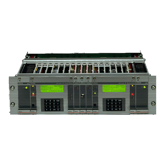
PS410 - RS232/RS485 Converter PS60X - Ethernet Server (Internal) Fig 1: Pakscan IIE Master Stations in a 19 inch rack The rack can accommodate two master stations, when viewed from the front these are referred to as M/S A on the left and M/S B on the right. The 19-inch rack is always fully wired to accommodate all variations of assembly within it. - Page 14 Field Terminals and D-type Connector IEC Power Connector Fig 2: Pakscan IIE Master Stations – rear view On the rear are the following items, repeated for both M/S A and M/S B. Power Connector (IEC) for use with a.c. powered units (when a 24V dc supply is used this is replaced by a terminal block).
-
Page 15: Storage Procedure
Storage STORAGE PROCEDURE On receipt the hardware should be examined for signs of damage and to ensure that the expected equipment is present. Identify all the parts. If the unit is to be stored for a period of time then normal conditions for keeping electronic hardware must be provided. - Page 16 Pakscan IIE System Manual (This page is intentionally blank) 16 of 132 Publication S177E V2.0 Issue 03/05...
-
Page 17: Overview Of Pakscan
Alternatively, one of the serial ports may Fig 3: Pakscan IIE System Diagram be used to drive a printer to log alarms. In the Pakscan Ethernet version one or both the serial ports are replaced with a standard 10Base-T Ethernet ports. -
Page 18: Control And Indication
Pakscan IIE System Manual Integral type field control units mounted within a Rotork actuator electrical housing such as the IQ, IQT or Q range actuator. Externally mounted field control unit. Various packages are available, including 'Pakbox', weather-proof box, or rack mounting. The unit may be used for either actuator control applications, or for general purpose applications such as pumps, blenders etc. -
Page 19: Functions
Fig 4: Loopback system 5.2 Current Loop Start Up Operations The Pakscan IIE controls the current on the loop to communicate with the attached field units. Loop communication divides into two parts: configuration (when the master station decides whether the loop is complete, and if not, where the faults are), and normal operation. -
Page 20: Loop Configuration
Pakscan IIE System Manual 5.2.1 Loop Configuration The loop configuration phase is entered after power-up, after a loop fault is detected, or after a loop configure command is received. Configuration consists of the following steps: Wait for all the field units to go into loopback. The time is dependent on the baud rate. -
Page 21: Modbus Serial And Ethernet Interfaces
5.3 Modbus Serial and Ethernet Interfaces The Pakscan IIE master station is provided with two interfaces for data exchange with external host systems. These may be a combination of one serial and one Ethernet, two serial or two Ethernet connections. - Page 22 Pakscan IIE System Manual (This page is intentionally blank) 22 of 132 Publication S177E V2.0 Issue 03/05...
-
Page 23: Initial Setting Up
Jumpers and Links INITIAL SETTING UP The factory default settings for the jumpers and links inside the master station will be satisfactory for most applications. However there are some cases where special settings could be required. Before applying any power to the master station check that the internal settings of the jumpers match the system requirements. - Page 24 Pakscan IIE System Manual J29 J7 Battery Jumper No Description Function Setting Reset jumper Normal operation Override reset Not fitted Hold in reset RAMWR jumper Normal operation Link 1 - 2 Full RAM access Not fitted CTR CLK2 jumper CTR CLK2 Freq - A ISAF –...
-
Page 25: External Links
Jumpers and Links J8 – CTS Function Select for Port 2 Link 2-3 (default setting) causes the master station to ignore the RS232 CTS line on Port 2. If the link is placed in 1-2, then the connected serial device may control the output of the master station on Port 2. -
Page 26: Display Screen Contrast
Pakscan IIE System Manual Terminal 22 & 23, Terminal 24 & 25 If the master station is not part of a hot standby pair, that is, it is a single stand-alone unit then two links MUST be fitted. (A hot standby pair always includes the PS300 switch module in the centre of the rack.) -
Page 27: Installation And Connection
Installation and Connection INSTALLATION AND CONNECTION The master station is now ready for installation and connecting to the loop. 7.1 Mounting The master station rack should be mounted horizontally in a suitable frame or cabinet. The height of the front should be between 1.0 m and 1.7 m above the floor so that the screen may be viewed and the keys accessed. -
Page 28: Field Wiring
Pakscan IIE System Manual 7.3 Field Wiring The field wiring includes the loop wires to the field units. The loop cable should have an overall electrical screen. Particular attention should be paid to the connection of the screen on this cable. -
Page 29: Screen Connections
Installation and Connection 7.3.1 Screen Connections The screen terminal 14 is connected internally to the supply earth pin, and the chassis. Terminal 17 is connected to earth via a capacitor, (to meet the CE specification for EMC emission standard), or directly to earth if link LK1 for master station A or hot standby systems, or LK2 for master station B, is fitted. -
Page 30: Screen Continuity
Pakscan IIE System Manual 2. Measure, and note down, the resistance of each core (the core connected to A and B will have a higher resistance than the core connected to the common). 3. Check the resistance between the cores, this should be a high resistance as they are not connected together. - Page 31 Installation and Connection Results of Cable Checks Resistance of Core 1 (A-B) Resistance of Core 2 (Common) Resistance between Core 1 and 2 Total Resistance of both Cores [should be the total of (1) and (2)] Screen end to end Resistance Cable to Screen Resistance [should be high] Screen to Earth Resistance [should be high] Capacitance Core to Core...
- Page 32 Pakscan IIE System Manual (This page is intentionally blank) 32 of 132 Publication S177E V2.0 Issue 03/05...
-
Page 33: Local User Interface
Interface and Menus LOCAL USER INTERFACE The master station has indication LEDs to show the condition of the hardware and also contains the main 4 line LCD display and keypad. This section describes the use of this display panel and also the menu structure for access to the various screens and settings for the system. -
Page 34: Lcd Screen And Keypad
Pakscan IIE System Manual 8.2 LCD Screen and Keypad The number keys (0 to 9) The LCD screen can display The CLEAR key clears a are used for numeric entry 4 lines of 20 characters and number currently being and also to select options... -
Page 35: Keypad Security
Interface and Menus 8.3 Keypad Security The Pakscan IIE master station can be protected against unauthorised changes by a password, or 'PIN', mechanism. Note: If a PIN has been programmed, it must be entered before particular functions can be accessed. These functions then remain accessible whilst keys are being pressed and for 30 seconds after the last key press. - Page 36 Pakscan IIE System Manual Top Menu – Master Station Status Master Station Status, Alarms and Tag Reset Loop (reconfigure the 2-wire loop) Start Configuration Mode (enable the use of MasterTools) Change Master (Hot Standby Systems only) Diagnostics (enter Diagnostic mode)
- Page 37 Interface and Menus Top Menu – Master Station Status Field Units Shows status of selected field unit For non IQ Actuators - Open command Close command Stop command Set Desired Value output Block and Parameter screen Alarms text Next alarm (if there is one) For General Purpose FCU Show relay output status Control relay 1...
-
Page 38: Master Station Status
Pakscan IIE System Manual 8.5 Master Station Status Master MSTAG001 Master tag Status=LB OFF Status 9>Alarms=P Alarms 1>M/S 2>Field Units Options This is the first master station screen that is displayed at power-up The Master Tag is an identity tag that can be configured by the user. -
Page 39: Master Station Commands
Config Mode forces the selected serial port to a fixed setup so that MasterTools utility can communicate via that port. The RS232/RS485 settings must be made independently. (MasterTools is the Rotork supplied utility used to read and write setup and tag data with a PC.) Commands available: Command to re-configure loop. -
Page 40: Master Station Alarms - Text Description
Pakscan IIE System Manual 8.5.2 Master Station Alarms - Text Description 1 System Alarms Number of system alarms Power up Reset Alarm description 1>Next Alarm View the next alarm This page gives an English text description of the master station alarms that appear as single letters on the Master Station Status screen. -
Page 41: Configuration Mode Screen
Interface and Menus 8.6 Configuration Mode Screen Select Port for Upload and Download: 1>Port 1 2>Port 2 This mode forces the selected port to adopt speed, protocol and address parameters that match the settings needed for the MasterTools utility. MasterTools runs on a PC and allows the master station settings to be modified using a PC screen and keyboard. -
Page 42: Diagnostic Menus
Pakscan IIE System Manual 8.7 Diagnostic Menus 8.7.1 Top Diagnostic Display S/W:0124 V5. 8/V5. 2 Software version 1>Port 1 Rx Tx Port 1 activity 2>Port 2 Rx Tx Port 2 activity 3>Loop >4 Loop diagnostics Inter-unit comms The top line shows the code for the software type fitted and its version numbers:... -
Page 43: Modbus Port Diagnostic Displays
Interface and Menus 8.7.2 Modbus Port Diagnostic Displays 1 msg xcpt crc Port number Message counts Mod func addr data 1920 Last message details The illustration shows the diagnostic display for Port 1, the display for Port 2 is similar. These screens give detailed diagnostic information for the serial links;... -
Page 44: Printer Port Diagnostic Display
Pakscan IIE System Manual 8.7.3 Printer port diagnostic display 1 len pin pout Port number Print queue The master station port 2 supports a serial (RS232) printer or similar generic device. If Port 2 is set for Printer use then the diagnostic display will be changed from that shown in section 8.7.2 Modbus Port Diagnostic Displays to the one shown above. -
Page 45: Loop Diagnostic Display
Interface and Menus 8.7.4 Loop Diagnostic Display Loop: Fault Found Reason for loop configuration Loop open circuit Fault Found Loopbacks at Address of fault details 1>Map 2>Test 3>Addr FCU map/Test/Address fault This screen provides information to aid in commissioning and fault finding on the current loop. Additional screens below this one also contain useful data on the loop status and connected field units. - Page 46 Pakscan IIE System Manual Commands available: Go to FCU map screen Loop speed test (only possible if loop is complete) Field Unit address fault details (only available if an address fault is present) Return to previous menu MENU 46 of 132...
-
Page 47: Fcu Map And Failure Counts
Interface and Menus 8.7.4.1 FCU Map and Failure Counts Loop Position = Physical position FCU Address Address Port=A Fails = Attached port Comms fail count Type=Act S/W = 2.07 Field unit type Software version The screen displays information about field units found on the loop during loop configuration. The top line shows the physical position on the loop, the second line the address of the field unit found at that position, and the third line the master station port it is attached to. -
Page 48: Loop Speed Test
Pakscan IIE System Manual 8.7.4.2 Loop Speed Test Loop Speed Test 1>Loop Speed = 1200 Speed selection 2>Test Perform test Result 100% Test result This screen allows the user to cause test messages to be sent around the loop at a defined baud rate. -
Page 49: Fcu Address Fault Details
Interface and Menus 8.7.4.3 FCU Address Fault Details FCU Address Fault Duplicate Address Address 10 15 on A & 139 on B This screen shows details of any address fault present on the loop. Line 2 shows the type of fault. Possible messages are Duplicate address - More than one field unit with the same address Address too High... -
Page 50: Hot Standby Inter Unit Diagnostic Display
Pakscan IIE System Manual 8.7.5 Hot Standby Inter Unit Diagnostic Display Inter-Unit Comms Clock OK Data OK Watchdog This screen gives information about the communications between the two units that make up a hot standby pair. It is intended mainly as an aid to testing and fault diagnosis. -
Page 51: Setup Menus
Interface and Menus 8.8 Setup Menus Note: The Setup options can be PIN protected. See sections 8.3 and 8.8.9 8.8.1 Top Setup Menu 1>Ports 2>Standby Port setup Only shows on hot standby units 3>Loop 4>Address Loop options Unit addresses 5>Tags 6>Time Set tag names Date and time... -
Page 52: Port Setup Menus
Pakscan IIE System Manual 8.8.2 Port Setup Menus 1>Port 1 2>Port 2 The first screen allows the port to be set up to be selected, press 1 or 2 for port 1 or 2. Press Menu to return to the previous menu. Once selected a screen similar to the following is revealed. -
Page 53: Alarm Linkage
Interface and Menus 8.8.2.1 Alarm Linkage Port Alarms 1>Separate This screen allows port alarm handling to be configured. Alarms can either operate completely independently (‘separate’) for each port, or can be linked such that the same alarm information is always reported regardless of which serial port is used. Alarms must be read and accepted before they can clear and return to normal. -
Page 54: Data Transfer To Standby Unit
Pakscan IIE System Manual 8.8.3 Data transfer to Standby Unit 1>Copy to Standby Copy data to standby unit 2>Copy address ON Copy master station address 3>Copy M/S tag ON Copy master station tag This page displays the “copy to standby” options and their current settings. This option is only available on hot standby master stations and allows data to be automatically transferred from the main unit to the standby unit. -
Page 55: Loop Setup Menu
Interface and Menus 8.8.4 Loop Setup Menu 1>Speed (now) = 1200 Current speed 2>Speed (new) = Desired speed 3>Number FCUs = Highest address 4>Doubling – OFF 5> Doubling enable More options This page displays and controls the options affecting the current loop. The master station can program the speed used on the loop. -
Page 56: Further Loop Options
Pakscan IIE System Manual 8.8.4.1 Further Loop Options 1>Retain data on Comms fail =OFF 2>IQ DV Convert=OFF Two further settings for the data on the loop can be made from this screen. There is an option to make the data held in the Modbus database for each FCU retain the last value obtained prior to loss of communication with the field unit should this occur. -
Page 57: Unit Address Setup Menu
Interface and Menus 8.8.5 Unit Address Setup Menu 1>Masterstation Modbus slave address The master station responds to messages directed at the Modbus slave address set using this page. Note that in some cases when using Pakscan Generic Modbus protocol settings the master station will respond to more than one address, and the setting here is the Base address. -
Page 58: Tag Setup Menu
Pakscan IIE System Manual 8.8.6 Tag Setup Menu 1>M/S Tag MSTAG001 Master station tag 2>FCU = FCU address 3> FCUTAG02 FCU’s tag This is the page for editing tag names that may be assigned to the master station and the field units. -
Page 59: Date And Time Setup
Interface and Menus 8.8.7 Date and Time Setup 1>Date 25/10/ 5 Date 2>Time 19:32:00 Time This page shows the state of the internal real-time clock. It is used to tag printer alarm messages with the time at which the alarm occurred and email messages from the Pakscan Ethernet alarm function when they are sent. -
Page 60: Esd Options Setup Menu
Pakscan IIE System Manual 8.8.8 ESD Options Setup Menu ESD Options 1>Serial Disabled 2>Keypad Disabled 3>Input Disabled This page allows the user to select the ESD (emergency shutdown) function. ESD operation can be enabled or disabled separately for the serial ports, the keypad, and the hardware input. The default setting for all three controls is all inputs disabled. -
Page 61: Keypad Security Options
Interface and Menus 8.8.9 Keypad Security Options Keypad Security 1>PIN In Use 2>PIN = **** 3>Access Level 3 A security code, PIN, can be set up to prevent unauthorised changes to the master station settings or field unit outputs. Line two shows ‘ PIN Not In Use ’ if no PIN has been set up and ‘ PIN In Use ’ once a PIN has been set. -
Page 62: Field Unit Menus
Pakscan IIE System Manual 8.9 Field Unit Menus The master station displays a screen appropriate to the type of field unit. 8.9.1 Actuator Field Unit Status Display OA1 ST0 MO0 FCUTAG01 Digital status Tag name CA0 MR0 MC0 Digital status FCU address MV=100% 9>Alms=P... -
Page 63: Iq Actuator Second Status Page
Interface and Menus 8.9.1.1 IQ Actuator Second Status Page Torq=85% FCUTAG01 Current torque Tag name Aux1=1 Aux2=0 Auxiliary inputs FCU address Aux3=0 Aux4=0 LoBat Battery status 1>Torque 2> More options This screen only appears for IQ and similar actuators, it shows the current torque value and the status of the 4 auxiliary digital inputs on an IQ actuator. -
Page 64: Iq And Iqt Historic Torque Displays
Pakscan IIE System Manual 8.9.1.2 IQ and IQT Historic Torque Displays Close Torq FCUTAG01 Open Torq FCUTAG01 92<Open 98<Open 1>Open 2>Reload 3> 1>Close 2>Reload 3> These screens show 8 values of torque for the actuator travelling in the opening or closing direction. -
Page 65: Flowpak Actuator Field Unit Status Display
Interface and Menus 8.9.2 Flowpak Actuator Field Unit Status Display OS1 ST0 TO0 FCUTAG01 Digital status Tag name CS0 TR0 TC0 Digital status FCU address MV=100% 9>Alms=P Measured value (position) Alarm status 1>O 2>C 3>S 4>DV 5> FCU commands More options Digital Status key: (The display shows a ‘0’... -
Page 66: General Purpose Field Unit Status Display
Pakscan IIE System Manual 8.9.3 General Purpose Field Unit Status Display DIN1->DIN8 FCUTAG01 Tag name 00001111 Digital inputs FCU address A1= 75% 9>Alms=P Measured value 1 Alarms A2= 50% 1>More Measured value 2 Commands page The status of the eight digital inputs is displayed as eight 0's or 1's. A 1 indicates that the input is true. -
Page 67: Second Page For General Purpose Field Unit
Interface and Menus 8.9.3.1 Second Page for General Purpose Field Unit Pulses= 44 FCUTAG01 Pulse counter Tag name 1>R1=0 2>R2=0 Relay commands FCU address 3>R3=0 4>R4=0 5>Aout= 6> Analogue output Block and parameter screen Digital input 1 on a GPFCU can be used as a pulse counter. The master station screen will count pulses up to 9999 before rolling over to 0 and starting again. -
Page 68: Iq Analogue Input Field Unit
Pakscan IIE System Manual 8.9.4 IQ Analogue Input Field Unit A1= 12% FCUTAG01 Analogue input channel 1 Tag name A2= 34% Analogue input channel 2 FCU address 9>Alms=P Alarms 5> Block and parameter screen The IQ actuator can contain two field units, each with their own loop address. The IQ Analogue Input field unit collects two analogue signals for display and reporting. -
Page 69: Communications Failure Display
Interface and Menus 8.9.5 Communications Failure Display FCUTAG01 Tag name FCU address Alarm : Comms Fail Alarm 5> Block and parameter screen This display is put up if the field unit is not in communication with the master station. FCUTAG01 Tag name FCU address Alarm : Comms Fail... -
Page 70: Field Unit Status Secondary Data
Pakscan IIE System Manual 8.9.6 Field Unit Status Secondary Data 1>Block= 5 FCUTAG01 Block Tag name 2>Para = Parameter FCU address 3>Data = Data Motion Inhibit Timer Name This page allows the user to read and change parameters in a field unit. Data in field units is organised into 32 blocks each of 8 parameters, the parameters within each block being related to each other, e.g. -
Page 71: Field Unit Alarm - Text Description
Interface and Menus 8.9.7 Field Unit Alarm – Text Description 3 Alarms FCUTAG01 Number of alarms Tag name FCU address Power up Reset Alarm description Alarm 1>Next Alarm View the next alarm This page gives an English text description of the FCU alarms that appear as single letters on the FCU status display screen. - Page 72 Pakscan IIE System Manual (This page is intentionally blank) 72 of 132 Publication S177E V2.0 Issue 03/05...
-
Page 73: Setting Parameters
Changes to the internal parameter settings can only be made if the PIN is known or disabled or the Access level is low enough. (When the master station leaves Rotork its PIN protection level is disabled, however, it may have been enabled by a third party before arriving on site). -
Page 74: Serial Communication Ports
Option 1 is fixed as host communication on this port. Pressing '2' will scroll round the available protocols, select the required. Note that the Rotork PC based plant control package, InVision, uses the Generic Modbus setting and Ethernet uses Generic Modbus when the web browser is required. -
Page 75: Loop Data
Setting Parameters When the settings are correct, press 'MENU' to return to the previous page. The chosen settings will only become active once you leave the 'set up' screen. Press ‘1’ and then '2' to select Port 2. The screen is very similar to the one for Port 1 except that Port 2 can be selected to operate a serial printer. -
Page 76: Tag Names
Pakscan II system as the baud rate doubling function will only operate successfully if all the field units are also upgraded to Pakscan IIE standards. Once these three parameters are set they will only become active when this screen is left by pressing 'MENU'. -
Page 77: Esd Configuration
Setting Parameters 9.6 ESD Configuration From the 'Top Setup Menu' as shown section 8.8.1, select option ‘7' to enter the ‘ESD Options Setup’. The screen revealed will be as shown in section 8.8.8. It is possible to enable or disable the ESD action from the 3 possible sources on the system. - Page 78 Pakscan IIE System Manual (This page is intentionally blank) 78 of 132 Publication S177E V2.0 Issue 03/05...
-
Page 79: Setting A Hot Standby Pair Parameters
Setting Hot Standby Pair Parameters 10 SETTING A HOT STANDBY PAIR PARAMETERS If the system is a Hot Standby pair then the rack will contain two identical master station PS100 modules, two Power Supplies, PS210, and a Switch module, PS300. In addition it may contain one or more Ethernet bridges and two PS410 RS232/RS485 converters. - Page 80 Pakscan IIE System Manual Ethernet Mains RJ45 Supply L N E PS604 Field Power Connector Supply PS210 Emergency Shutdown Port 1 RS485 Actuator Terminals Port A Out Processors Port A In Port 2 RS232 Display Signal Earth Bar PS100 Screen of 2 wire loop connected...
-
Page 81: Hot Standby Parameter Setting And Options
Setting Hot Standby Pair Parameters 10.3 Hot Standby Parameter Setting and Options When setting the communication port options, as described in 9.2 above, there is an additional option on the screen shown in section 8.8.2. With a master station module, in a hot standby pair, it is possible to set it up to be Active or Passive when in standby mode by pressing button '5'. - Page 82 Pakscan IIE System Manual The key rotates through 4 positions and is only removable in the Auto position. Select Auto for normal operation Select position B before removing master station A Select position A before removing master station B There are no electronic components on the PS300 module and its function is solely to allow a unit to be removed for repair.
-
Page 83: Including A Ps410 Converter
PS410 Converter 11 INCLUDING A PS410 CONVERTER Within the master station rack there are two pre-allocated positions for PS410 RS232/RS485 converter modules. These are fitted when there is a need for two RS485 or two RS232 highways to the master station. Occasionally they may also be fitted to accommodate the requirements for dual Ethernet communications. -
Page 84: Jumper Functions
Pakscan IIE System Manual 11.1 Jumper functions Internally the PS410 has several jumpers used to configure the card to match the performance required. Once the function has been set the next most important setting is the use of bias and termination resistors on the RS485 highway. -
Page 85: Ps410 Port 1 To Rs232 Setup
PS410 Converter 11.1.2 PS410 port 1 to RS232 setup To use the converter to convert the master station RS485 port (Port 1) to a second RS232 port. Set J1 to positions 1-2, 4-5 and 7-8 (marked ’PORT 1 TO RS232’ on the PCB) Set J2 according to the baud rate being used Set J7 to positions 1-2 and 7-8 (2-wire mode) Set jumpers J3, J4, J5 and J6 according to Section 11.1.4... -
Page 86: 2-Wire And 4-Wire Rs485 Communications
Tx + Tx – Rx + Rx – Signal ground Transmitted and received data have their own pairs of wires. The Pakscan IIE master station Port 1 supports 2-wire RS485 communications only. 86 of 132 Publication S177E V2.0 Issue 03/05... -
Page 87: Setting Up And Using The Ps600 Ethernet Module
12 SETTING UP AND USING THE PS600 ETHERNET MODULE The Pakscan IIE master station may include PS601/2/3/4 Ethernet modules to allow direct Ethernet connection to the control system. These modules connect to either one or both stations when a hot standby system is being used. -
Page 88: Internal Connections
Pakscan IIE System Manual 12.1 Internal Connections The module is connected to the master station port 1, 2 or 4 using an RJ12 connector on the module and the 9 way D type on the rear of the rack. The cable used is specific to the type of connection, either RS232 or RS485. -
Page 89: Local Ethernet Connection
Ethernet Connection Once connected to the PC, either via a LAN or directly, the Ethernet bridge may then be set up or the web pages accessed. 12.2.1 Local Ethernet Connection The Ethernet bridge default I/P address is: 10.200.1.1 . For local Ethernet connection, consult your network administrator. The LAN administrator will control the rules and permissions used on your site. -
Page 90: Ethernet Module Status Indicators
Pakscan IIE System Manual 12.3 Ethernet Module Status Indicators COM 1 Module Status Serial Link Status Activity/Collision Link EIA-232 Ethernet Fig 21: Top view of the Ethernet bridge module The module includes four bi-colour LED’s that are used to show the status and activity of the device. -
Page 91: Setting Up The Module
Ethernet Connection 12.4 Setting Up the Module Once the PC is connected to the master station either by a cross over cable or locally via the LAN it can be set up for the particular application for which it is intended. The following notes assume that Microsoft Internet Explorer is used as the web browser for the connection. -
Page 92: Setting The Serial Connection Fields
Pakscan IIE System Manual Admin Area Fig 24: Web Server opening screen 12.4.1 Setting the Serial Connection Fields Click on the Admin Area then select Serial from the menu that appears below Admin Area. Serial Fig 25: Serial Comms to PS100 setup screen The serial communication screen allows the settings between the bridge and the PS100 module to be set. -
Page 93: Setting The User Fields For The Web Browser
Ethernet Connection • If the host Modbus TCP connection requires Generic Modbus or Honeywell PLCG protocol, set the mode to Generic Modbus. Note that the analogue data format is the only difference between these two data bases. • If the host Modbus TCP connection requires Yokogawa or Honeywell SI protocol, set the mode to Yokogawa. - Page 94 Pakscan IIE System Manual Fig 27: Users profile setup screen The user profile fields are entered as appropriate. Only administrators have access to these fields. Field Function Example User ID Name of the user as entered in the initial connection...
-
Page 95: Setting The Alarm Messaging Information
Ethernet Connection 12.4.3 Setting the Alarm Messaging Information Emails may be used to report critical alarms. The email messages sent to the specified recipients are the same for all recipients. The decision about who gets the message is made in the user profile. This screen allows the information to be sent in email form to be selected. -
Page 96: Setting The Local Area Network Connection Parameters
Pakscan IIE System Manual 12.4.4 Setting the Local Area Network Connection Parameters The settings for the Ethernet connection are made from the Network screen. Network Fig 29: Network parameter setup screen The LAN system administrator will normally provide the IP address and other settings. The settings will depend on how the network has been set up. -
Page 97: Using The Ethernet Connection
The overview screen is the first screen displayed after a successful log in. The display will show either a Pakscan IIE or Pakscan IIS master station depending on the type of station accessed. All users will have access to view the status, but only specified users can issue commands. When a command is selected such as Alarm Accept or Reset Loop a pop-up confirmation box appears and acceptance is required before the action takes place. -
Page 98: Master Station Configuration
Pakscan IIE System Manual 12.5.2 Master Station Configuration The master station settings can be viewed from this screen. Users with Administrator access are permitted to alter the settings, but great care must be taken when doing so as the results can lead to loss of control or communication with the system. -
Page 99: Network Diagnostics
Ethernet Connection Some of the fields are fixed and cannot be altered from this screen as they are used to report basic settings of the system. Note: Do not alter the Host Port Configuration for the serial port connected to the Pakscan Ethernet module. -
Page 100: Fcu Menu
Pakscan IIE System Manual The screen automatically builds a list showing all the field units in the order in which they are wired on the Pakscan loop. For this loop to be complete the actuators must all be powered up. The list includes details on the device type, the tag entered and the number of times the field unit has failed to respond. -
Page 101: Field Unit Status And Control
Ethernet Connection 12.5.4.1 Field Unit Status and Control The FCU Control button brings up an additional screen that shows the current status of the actuator at that address. Slider Fig 34: FCU Status and Control screen The basic status of the actuator is shown on the left and the picture on the right shows the type of actuator. -
Page 102: Field Unit Alarms Screen
Pakscan IIE System Manual 12.5.4.2 Field Unit Alarms screen The alarm panel appears when the ‘Show Alarms’ button is clicked. Fig 35: FCU Alarm screen Any alarm that is present will be shown by a red symbol and alarms can be accepted from this screen. -
Page 103: Fcu Parameters
Ethernet Connection The torque profile is shown in bar format for the last open to close and close to open valve movements. Note: Historical Torque transmission must be enabled in the IQ field unit for this feature to become active. To make the FCU report the historical torque data the Torque Filter Factor must be set to 0. - Page 104 Pakscan IIE System Manual Fig 38: Tag List and Parameter access screen The field units are listed in address order and clicking the FCU parameter button leads to the individual field unit parameter screen. Fig 39: FCU Parameter screen Every field unit has a number of configurable parameter settings that determine its operation in the network.
- Page 105 Ethernet Connection be available or function as expected. These screens allow the settings of all the field unit parameters to be examined including those relating to the operation on the network. Note: Information about the field unit settings can be seen in the parameters listed, but alterations cannot be made from this connection.
- Page 106 Pakscan IIE System Manual (This page is intentionally blank) 106 of 132 Publication S177E V2.0 Issue 03/05...
-
Page 107: Commissioning The System
Commissioning the System 13 COMMISSIONING THE SYSTEM IMPORTANT SAFETY PRECAUTIONS In order to fully commission the Pakscan Loop it is necessary to ensure that all the system's valves are allowed to be opened and closed. Also any ancillary devices such as pumps and stirrers must be allowed to operate. -
Page 108: Checking The Loop Itself
Pakscan IIE System Manual Make sure that no two field units on the loop have the same address, and that no field unit has an address set higher than that selected as 'the highest address' - see section 9.3. When setting and checking a field unit remember that the Paktester will only communicate to one field unit at a time, the one to which it is connected. - Page 109 Commissioning the System The status screen will show 'Waiting for Loopbacks 1', and be followed by 'Finding FCU A’, ‘Finding FCU B’, ‘Waiting for Loopbacks 2’, ‘Loopbacks Off A’, ‘Loopbacks Off B’ and finally ‘Loopback On’. Now press '1' to select the master station commands, followed by '4' to select the diagnostic screen. This is illustrated in section 8.7.4.
-
Page 110: Checking System Performance
Pakscan IIE System Manual 13.3 Checking System Performance In section 9.3 it was recommended to set Baud Rate Doubling ‘OFF’. Once the loop is up and running this may be changed to 'Doubling On'. 13.3.1 Setting the Loop Driver Voltages In most systems it is not necessary to trim the loop driver card voltages to optimise the performance. -
Page 111: Diagnostic Information
Commissioning the System Vmax Videal Field Unit Reply Master Station Request Vmax Adjustable by the potentiometers at the master station Videal The ideal voltage is 3 volts above V (Note that the actual waveform may be rounded due to the charging and discharging of line capacitance.) Fig 40: Idealised Loop Waveform, monitored at the master station 13.4 Diagnostic Information The master station can provide information via its own display that can help in commissioning and... -
Page 112: Loop Communications
Pakscan IIE System Manual before the loop fault. The Port A, then Port B LED's, flicker during this stage. Normal scanning of a broken loop shows up as both LED's flickering, but not together. Should the setting of field unit parameters have been carried out incorrectly then the system will identify a field unit that has an address to high or duplicated with another and eliminate these from the routine data polling. -
Page 113: Checking Host Communications
Commissioning the System The master station should now be in communication with ALL the field units at the lower speed. Repeat the whole procedure if not. In some cases individual field units may need to be reprogrammed with a Paktester or IQ Setting Tool. 13.4.4 Checking Host Communications If there are no communications between host and master station, check the diagnostic screen's 'Rx' and 'Tx' flags. -
Page 114: Commissioning Aids
Pakscan IIE System Manual 13.6 Commissioning Aids Two handheld devices are available to aid commissioning and fault finding. The first is the Paktester, (Field Test Unit), that may be used to interrogate and control a single field unit via the 2-wire interface. -
Page 115: Master Station Software Version
The serial number will be found on a data label on the rear of the unit. The master station type includes a code as follows: S/W Type : X X X X 01 = Pakscan IIE system = Single Unit = Hot Standby unit... - Page 116 Pakscan IIE System Manual (This page is intentionally blank) 116 of 132 Publication S177E V2.0 Issue 03/05...
-
Page 117: Set Up Data Records
Set Up Data Records 15 SET UP DATA RECORDS A copy of the following table should be completed for every master station in the system. Keep the record safe so that in the unlikely event of a failure settings can quickly be restored when replacing a unit. -
Page 118: Loop Map
Pakscan IIE System Manual 15.1 Loop Map Complete the following chart showing the position and address and type of each field unit Position Address Type Position Address Type For each field unit, record the settings made for the performance of the field unit. - Page 119 Set Up Data Records IQ Actuator Field Units Actuator Type ……………….. ……………….. Address ……………….. Baud Rate ……………….. Analogue Update Time ……………….. Analogue deviation Threshold ……………….. Motion Inhibit Time ……………….. Motion Inhibit Deadband ……………….. Torque Update Time ……………….. Torque Update Deviation ………………..
- Page 120 Pakscan IIE System Manual (This page is intentionally blank) 120 of 132 Publication S177E V2.0 Issue 03/05...
-
Page 121: Technical Specifications
300 mA at 24V dc or 130 mA at 125V ac 16.2 Actuator Field Units For data on field units fitted inside Rotork actuators refer to the actuator or field unit data sheets. The integral field units operate in the same environment as the actuator, using the actuator power supply and communicating commands and data directly with the actuator electronics. -
Page 122: Gp Field Unit
Pakscan IIE System Manual 16.3 GP Field Unit Environmental Spec Operating Temperature -30 to +70 Storage Temperature -40 to +85 Power Supply 110V ac +/-20%, 240V ac +/-10%, 50/60Hz +/- 1Hz Output Relays 2A, 130V, 60W, 125VA (exclusive maxima) 16.4 2-Wire Loop Cables The recommended cables to use for the loop wiring should be a twisted pair with an overall screen. - Page 123 Technical Specifications From the cable data and the figures for the maximum permissible resistance and capacitance at each baud rate the maximum cable distances can be calculated for each baud rate. Note that the loop distance is the length of the twisted pair cable. Loop Distance (km) with 1.5mm cable Number of FCU...
-
Page 124: External Connections
Pakscan IIE System Manual 16.5 External Connections The following information applies to the connectors that are on the rear panel of the 19-inch rack. 16.5.1 Loop Connections and Digital I/O Terminal Number & Loop Connections and digital I/O are brought to... -
Page 125: Serial Ports
Technical Specifications 16.5.2 Serial Ports Serial Port 1 (the RS485 port) Port 1 – RS485 Port 1 has a pair of 9-way D-type connectors, one male and one Pin No. Function female. The connections are shown in the table. The RS485 port has a true tri-state output allowing 2-wire communications to be used. - Page 126 Pakscan IIE System Manual Serial Port 4 (the PS410 RS485 port) Port 4 – RS485 Port 4 has a 9-way D-type female connector. The connections are 2 wire 4 wire shown in the table for both 2 and 4 wire connections. Internal Pin No.
-
Page 127: Printer Messages
Motor Running – End Of Travel Not all field units support all types of alarm 16.7 Maintenance The Pakscan IIE master station is not suitable for field repair. Should the unit require maintenance contact your local Rotork representative. Battery Replacement The master station contains a long life battery that should last for at least 3 years when no power is applied and considerably longer in normal use. -
Page 128: Master Station Dimensions
PORT 4 holes 7 dia Front view terminals and connectors handles (all dimensions in mm) Plan view Fig 45: Pakscan IIE master station dimensions Weight: Single master station 5.2 kg Dual master station 6.8 kg Hot Standby master station 6.9 kg 128 of 132 Publication S177E V2.0 Issue 03/05... -
Page 129: General Safety Information
If such excess is applied, the product should be returned to Rotork or otherwise checked by a competent person before re-use, even if no damage is immediately evident. Use only the specified fuse type and rating as replacements. - Page 130 Reliability predictions, (including failure mode and effect analysis), are calculated by Rotork using statistical methods and the resulting figures should only be used for statistical purposes. These predictions are only valid if the maintenance procedures and maintenance intervals stated in Rotork documentation are observed.
- Page 131 (This page is intentionally blank) 131 of 132 Publication S177E V2.0 Issue 12/04...
- Page 132 675 Mile Crossing Blvd England Rochester BA1 3JQ New York 14624 Rotork reserves the right to amend and change specifications without prior notice. Tel: +44 (0) 1225 733 200 Tel: +1 716 328 1550 Fax: +44 (0) 1225 333 467...
Need help?
Do you have a question about the Pakscan IIE and is the answer not in the manual?
Questions and answers