Sign In
Upload
Manuals
Brands
rotork Manuals
Control Systems
Pakscan IIE
User Manuals: rotork Pakscan IIE Network Control System
Manuals and User Guides for rotork Pakscan IIE Network Control System. We have
1
rotork Pakscan IIE Network Control System manual available for free PDF download: System Manual
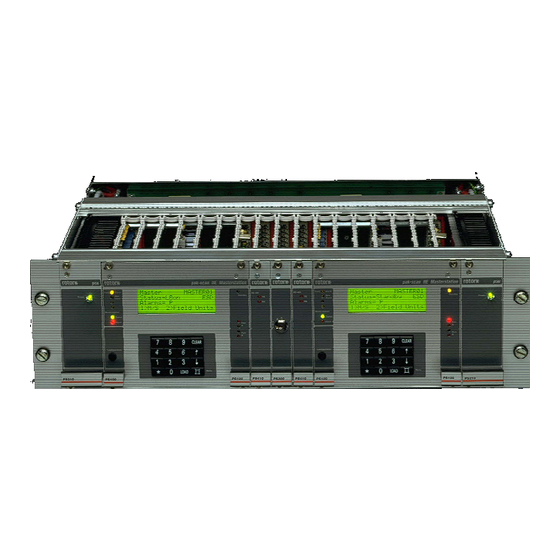
rotork Pakscan IIE System Manual (132 pages)
Brand:
rotork
| Category:
Control Systems
| Size: 4 MB
Table of Contents
Table of Contents
3
Glossary of Terms
7
Abbreviations
7
How to Use this Manual
9
Software Level
9
1 Introduction
11
Related Documents
11
2 Equipment Description
13
3 Storage Procedure
15
4 Overview of Pakscan
17
Field Control Units
17
Control and Indication
18
5 Functions
19
Cable Fault Protection - Loopback System
19
Current Loop Start up Operations
19
Loop Configuration
20
Normal Running Operation
20
Modbus Serial and Ethernet Interfaces
21
Local User Interface (LCD and Keypad)
21
6 Initial Setting up
23
Jumper Settings
23
External Links
25
Display Screen Contrast
26
7 Installation and Connection
27
Mounting
27
Mains Power
27
Field Wiring
28
Screen Connections
29
Loop Checks
29
Loop Continuity
29
Screen Continuity
30
Cable Capacitance
30
8 Local User Interface
33
Front Panel Indication Leds
33
LCD Screen and Keypad
34
Keypad Security
35
Using a PIN
35
Menu Structure
35
Master Station Status
38
Master Station Commands
39
Master Station Alarms - Text Description
40
Configuration Mode Screen
41
Diagnostic Menus
42
Top Diagnostic Display
42
Modbus Port Diagnostic Displays
43
Printer Port Diagnostic Display
44
Loop Diagnostic Display
45
FCU Map and Failure Counts
47
Loop Speed Test
48
FCU Address Fault Details
49
Hot Standby Inter Unit Diagnostic Display
50
Setup Menus
51
Top Setup Menu
51
Port Setup Menus
52
Alarm Linkage
53
Data Transfer to Standby Unit
54
Loop Setup Menu
55
Further Loop Options
56
Unit Address Setup Menu
57
Tag Setup Menu
58
Date and Time Setup
59
ESD Options Setup Menu
60
Keypad Security Options
61
Field Unit Menus
62
Actuator Field Unit Status Display
62
IQ Actuator Second Status Page
63
IQ and IQT Historic Torque Displays
64
Flowpak Actuator Field Unit Status Display
65
General Purpose Field Unit Status Display
66
Second Page for General Purpose Field Unit
67
IQ Analogue Input Field Unit
68
Communications Failure Display
69
Field Unit Status Secondary Data
70
Field Unit Alarm - Text Description
71
9 Setting Parameters
73
Initial Decisions
73
Serial Communication Ports
74
Loop Data
75
Tag Names
76
Date and Time
76
ESD Configuration
77
Security Access Level
77
Final Checks
77
10 Setting a Hot Standby Pair Parameters
79
Copy Data a to B
79
Changes to Terminal Connections
79
Main/Standby Connections
79
Hot Standby Parameter Setting and Options
81
The PS300 Keyswitch
81
11 Including a Ps410 Converter
83
Jumper Functions
84
PS410 Port 2 to RS485 Setup
84
PS410 Port 1 to RS232 Setup
85
LED Functions
85
RS485 Line Conditioning
85
2-Wire and 4-Wire RS485 Communications
86
12 Setting up and Using the Ps600 Ethernet Module
87
Internal Connections
88
Connecting to the Ethernet Bridge
88
Local Ethernet Connection
89
Direct Ethernet Connection to a PC
89
Connection Using Windows XP
89
Ethernet Module Status Indicators
90
LED Functionality
90
Setting up the Module
91
Setting the Serial Connection Fields
92
Setting the User Fields for the Web Browser
93
Setting the Alarm Messaging Information
95
Setting the Local Area Network Connection Parameters
96
Using the Ethernet Connection
97
Master Station Overview
97
Master Station Configuration
98
Network Diagnostics
99
FCU Menu
100
Field Unit Status and Control
101
Field Unit Alarms Screen
102
IQ and IQT Actuator Torque Screen
102
FCU Parameters
103
13 Commissioning the System
107
Checking Individual Field Units
107
Checking the Loop Itself
108
Checking System Performance
110
Setting the Loop Driver Voltages
110
Diagnostic Information
111
Loop Configuration
111
Loop Communications
112
Loop Speed Reprogramming
112
Checking Host Communications
113
Final Checks
113
Commissioning Aids
114
14 Master Station Software Version
115
15 Set up Data Records
117
Loop Map
118
16 Technical Specifications
121
Master Station
121
Actuator Field Units
121
GP Field Unit
122
2-Wire Loop
122
External Connections
124
Loop Connections and Digital I/O
124
Serial Ports
125
Printer Messages
127
Maintenance
127
Master Station Dimensions
128
17 General Safety Information
129
Advertisement
Advertisement
Related Products
rotork p3
rotork Paksan P3F
rotork Pakscan IIS
rotork Pakscan Paktester
rotork Pakscan GPFCU
rotork Profibus PB
rotork Pro v1.1
rotork FAIRCHILD PAX1
rotork Categories
Controller
Valve Positioners
Industrial Equipment
Control Unit
Control Systems
More rotork Manuals
Login
Sign In
OR
Sign in with Facebook
Sign in with Google
Upload manual
Upload from disk
Upload from URL