Table of Contents
Advertisement
Advertisement
Table of Contents

Related Manuals for Exerpeutic 1112.8-101016


Summary of Contents for Exerpeutic 1112.8-101016
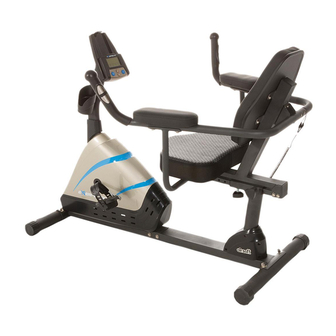
- Page 1 Programmable Recumbent Bike IMPORTANT: Read all instructions carefully before using this product. Retain this owner’s manual for future reference. The specifications of this product may vary from this photo, subject to change without notice. OWNER’S MANUAL 1112.8-101016...
-
Page 3: Table Of Contents
TABLE OF CONTENTS SERVICE ------------------------------------------------------------------------ 2 LABEL PLACEMENT --------------------------------------------------------- 3 PRODUCT SAFETY ---------------------------------------------------------- 4 OVERVIEW DRAWING ------------------------------------------------------ 5 PARTS LIST -------------------------------------------------------------------- 6 ASSEMBLY GROUPS --------------------------------------------------------8 ASSEMBLY GROUPS LIST ------------------------------------------------ 9 HARDWARE PACK------------------------------------------------------------ 10 ASSEMBLY ---------------------------------------------------------------------- 11 COMPUTER --------------------------------------------------------------------- 22 ADJUSTMENTS ---------------------------------------------------------------- 27 TRANSPORTATION----------------------------------------------------------- 28 TROUBLE SHOOTING &... -
Page 4: Service
SERVICE IMPORTANT: FOR NORTH AMERICA ONLY For damaged or defective product, questions, replacement parts or any other service support, please contact our customer service department (8:00 AM - 5:00 PM Pacific Standard Time, Daily) by the below methods: For Best Service, please Email: Service@paradigmhw.com Response Time: 1-2 Business Days Website:... -
Page 5: Label Placement
LABEL PLACEMENT... -
Page 6: Product Safety
PRODUCT SAFETY Basic precautions should always be followed when using this equipment. Read all instructions before using this equipment which include the following safety instructions: Read all the instructions in this manual and do warm up exercises before using this equipment. Before exercising, and in order to avoid injuring your muscles, it is recommended that you perform warm-up exercises for every muscle group. -
Page 7: Overview Drawing
OVERVIEW DRAWING... -
Page 8: Parts List
PARTS LIST Description Description Handrail End Cap Ø32x1.5 2 025 Bushing Bolt M6x15 4 026 Rear Main Frame Extension Hand Pulse Sensor Washer Ø6xØ12x1.0 5 029 Wire I L=1300 mm Phillips Self Tapping Screw Left Handrail Ø32x1.5x1085 1 030 ST4.8x20 Backrest 407x364x50 1 031 Right Decorate Cover Ø60... - Page 9 PARTS LIST Description Qty No. Description 051 Extension Sensor Wire L=600 mm 1 077 Front Stabilizer End Cap Ø60 052 Screw ST2.9x12 2 078 Front Stabilizer Ø60x1.5x580 053 Sensor with Wire L=300 mm 1 079 Bolt M6x45 054 Front Post Cover 1 080 Transport Wheel Ø23xØ6x32 Extension Hand Pulse Sensor...
-
Page 10: Assembly Groups
ASSEMBLY GROUP... -
Page 11: Assembly Groups List
ASSEMBLY GROUP LIST Assembly Description Group Right Handrail Ø32x1.5x929 Handrail End Cap Ø32x1.5 Hand Pulse Sensor with Wire L=1150 mm Screw ST4.2x30 Handrail Foam Grip Ø31xØ37x230 Left Handrail Ø32x1.5x1085 Handrail End Cap Ø32x1.5 Hand Pulse Sensor with Wire L=1150 mm Screw ST4.2x30 Handrail Foam Grip Ø31xØ37x230 Extension Hand Pulse Sensor Wire L=200 mm... -
Page 12: Hardware Pack
HARDWARE PACK... -
Page 13: Assembly
ASSEMBLY Tool Multi Hex Tool with Phillips Screwdriver S10, S13, S14, S15 Front Stabilizer Installation Lift up the Front Main Frame (73) and align the Front Stabilizer (78) onto the front curve of the Front Main Frame (73). Attach two Bolts (37) and on the other ends of bolts attach two Big Curve Washers (36) and two Cap Nuts (35). - Page 14 ASSEMBLY Tool Multi Hex Tool with Phillips Screwdriver S10, S13, S14, S15 Rear Stabilizer Installation Lift up the Rear Main Frame (26), and align the Rear Stabilizer (38) onto the rear curve of the Rear Main Frame (26). Attach two Bolts (37) and on the other ends of bolts attach two Big Curve Washers (36) and two Cap Nuts (35).
- Page 15 ASSEMBLY Tool: Allen Wrench 6mm 1 PC Rear Main Frame Installation Use the 6mm Allen Wrench with Phillips Screwdriver to remove six Bolts (39) and six Washers (40) from the Rear Main Frame (26). Connect the Extension Hand Pulse Sensor Wire I (29) from the Rear Main Frame (26) with the Extension Hand Pulse Sensor Wire II (55) from the Front Main Frame (73).
- Page 16 ASSEMBLY Tool: 5mm Allen Wrench 4.1 Right/Left Handrail Support Tubes Installation Use the Multi Hex Tool with Phillips Screwdriver to remove four Bolts (24) from the Back and Seat Support Bracket (17). Align and hold the Right Handrail Support Tube (21) onto the Back and Seat Support Bracket (17), use the Multi Hex Tool with Phillips Screwdriver to tighten the Bolts (24) until secure.
-
Page 17: Bushing
ASSEMBLY Tool: 6mm Allen Wrench with Phillips Screwdriver 1 PC 5. Back/Seat Support Bracket Installation Use the 6mm Allen Wrench with Phillips Screwdriver to remove eight Bolts (39) and eight Washers (40) from the Seat Sliding Tube (15). Insert the Seat Sliding Tube (15) into the Bushings (25) of the Rear Main Frame (26). -
Page 18: Extension Hand Pulse Sensor
ASSEMBLY Tool: 6mm Allen Wrench with Phillips Screwdriver 1 PC 6. Front Post and Front Post Cover and Foot Pedals Installation Use the 6mm Allen Wrench with Phillips Screwdriver to remove four Washers (40), four Bolts (49), one bolt (39), and one Big Curve Washer (36) from the tube of the Front Main Frame (73). - Page 19 ASSEMBLY Tool: Multi Hex Tool with Phillips Screwdriver S10, S13, S14, S15 7. Left and Right Foot Pedals Installation The Cranks, Pedal Shafts, and Foot Pedals are marked “R” for Right and “L” for Left. Insert the Left Foot Pedal (63) into the threaded hole in the left Crank (62). Turn the pedal shaft by hand in a counter-clockwise direction until snug.
-
Page 20: Extension Hand Pulse Sensor
ASSEMBLY Tool: Multi Hex Tool with Phillips Screwdriver S10, S13, S14, S15 Left/Right Handrails and Backrest Installation Use the Multi Hex Tool with Phillips Screwdriver to remove four Big Washers (18) and four Bolts (19) from the Backrest (5).Align and hold the Backrest (5) onto the Back and Seat Support Bracket (17), use the Multi Hex Tool with Phillips Screwdriver to tighten four Big Washers (18) and four Bolts (19) until firm and secure. - Page 21 ASSEMBLY Tool: Allen Wrench 5mm 9. Armrests Installation Align and hold the Armrest (20) onto the Right Handrail (12), use the 5mm Allen Wrench to tighten two Bolts (22) and two Big Curve Washers (10) until firm and secure. Repeat these steps to the other Armrest (20) onto the Left Handrail (4). Hardware: (#22) Bolt (#10) Big Curve Washer...
-
Page 22: Bottle Holder
ASSEMBLY 10. Computer and Bottle Holder Installation Use the Multi Hex Tool with Phillips Screwdriver to remove four Bolts (45) from the Computer (43). Connect the Extension Hand Pulse Sensor Wires III (44) and Extension Sensor Wire I (50) to the wires that come from the Computer (43). Tuck these wires into the Front Post (48) and attach the Computer (43) onto the Front Post (48) with the four Bolts (45) that were removed. - Page 23 ASSEMBLY 11. Adapter Installation Plug one end of the Adapter (76) into the power jack of the Power Supply Cable (74) on the Left Cover (71). Before plugging in, make sure to carefully check the specifications on the Adapter. Plug the other end of the Adapter (76) into the electrical wall outlet.
-
Page 24: Computer
COMPUTER There are 3 basic training program modes: 1 Manual, 5 Pre-programs, and 1 User Program. Button Functions: START/STOP: Press the START/STOP button to start or stop exercise. Press and hold the START/STOP button for 3 seconds, to reset all values to 0. UP: Press the UP button to navigate through the training program modes (Manual, Pre-set Programs, or User Program). -
Page 25: Display Functions
COMPUTER Display Functions: SCAN: The computer will display each function every 6 seconds. SPEED/RPM/TIME/DISTANCE/CALORIES/PULSE. SPEED: Displays the current speed. The split window of SPEED and RPM will display SPEED and RPM alternately every 6 seconds. RPM: Displays the current RPM (Rotation per Minute). The split window of SPEED and RPM will display SPEED and RPM alternately every 6 seconds. - Page 26 COMPUTER Operating Ranges Function Range (Count up) Count down Default Value Increment (Decrement) TIME (MIN: SEC) 0:00 ~ 99:59 99:00 ~ 5:00 0:00 1:00 DISTANCE (MPH) 0.00 ~ 99.9 99.50 ~ 0.5 0.00 CALORIES (KCAL) 0 ~ 9999 9990 ~ 10 10.0 PULSE (BEATS/MIN) 40 ~ 240...
- Page 27 COMPUTER Pre-programs: There are 5 Pre-set Programs for use: INTERVALS, CLIMBING, HILL, PLATEAU, and VALLEY. Press the UP or DOWN button to select one of five Pre-set Programs, Then press the SET button to edit the Pre-Set Program. Set a target Time using the UP and DOWN buttons, Then Press the Set Button to confirm the target time.
-
Page 28: User Program
COMPUTER User Program: There is one User Program available for creating a Custom program. Users are free to set the values in the order of TIME, DISTANCE, CALORIES, PULSE, and LEVEL. The values and profiles will be stored in the memory after setup. Press the UP or DOWN button to select User Program, the “... -
Page 29: Adjustments
ADJUSTMENTS Adjustable Leveler (42) Rear Stabilizer End Cap (34) Adjusting the Rear Stabilizer End Cap or Adjustable Leveler Turn the Rear Stabilizer End Caps (34) or the Adjustable Leveler (42) as needed to the level the Bike with the ground. Adjusting the Seat Forward or Back Turn the L Shape Knob (97) in a counter-clockwise direction until it can be pulled out. -
Page 30: Transportation
TRANSPORTATION Transporting the Bike Hold the Handlebar (4/12) and tilt the bike forward until the wheels on the Front Stabilizer (80) make contact with the floor. Push or pull the unit to the desired location before gently lowering the Rear Stabilizer (38) back down to the ground. -
Page 31: Trouble Shooting & Maintenance
TROUBLE SHOOTING & MAINTENANCE TROUBLE SHOOTING PROBLEM: The recumbent bike wobbles when in use. SOLUTION: Turn the Rear Stabilizer End Caps on the Rear Stabilizer or Adjustable Leveler on the bottom of the Rear Main Frame as needed to level the recumbent bike. -
Page 32: Warranty
WARRANTY MANUFACTURER’S LIMITED WARRANTY Paradigm Health & Wellness warrants to the original purchaser that this product is free from defects in material and workmanship when used for the purpose intended, under the conditions that it has been installed and operated in accordance with Paradigm’s Owner’s Manual. -
Page 33: Parts Request Form
PARTS REQUEST FORM Paradigm Health & Wellness, Inc. EMAIL THIS FORM WITH YOUR RECIEPT OF PURCHASE TO Service@paradigmhw.com NAME: _______________________________________________________ ADDRESS: ____________________________________________________ CITY ______________ STATE ______________ ZIP ___________________ TELEPHONE: (Day) _____________________________________________ (Night) ____________________________________________ SERIAL#: _____________________________________________________ MODEL#: _____________________________________________________ PURCHASE DATE: ______________________________________________ PLACE OF PURCHASE: _________________________________________ PART # DESCRIPTION...
Need help?
Do you have a question about the 1112.8-101016 and is the answer not in the manual?
Questions and answers