Table of Contents
Advertisement
Quick Links
One Technology Way • P.O. Box 9106 • Norwood, MA 02062-9106, U.S.A. • Tel: 781.329.4700 • Fax: 781.461.3113 • www.analog.com
Evaluating the AD9650/AD9268/AD9258/AD9251/AD9231/AD9204/
FEATURES
Full featured evaluation board for the AD9650/AD9268/
AD9258/AD9251/AD9231/AD9204/AD9269/AD6659
SPI interface for setup and control
External, on-board oscillator, or AD9517 clocking options
Balun/transformer or amplifier input drive options
LDO regulator or switching power supply options
VisualAnalog® and SPI controller software interfaces
EQUIPMENT NEEDED
Analog signal source and antialiasing filter
Sample clock source (if not using the on-board oscillator)
2 switching power supplies (6.0 V, 2.5 A),
CUI EPS060250UH-PHP-SZ, provided
PC running Windows® 98 (2nd ed.), Windows 2000,
Windows ME, or Windows XP
USB 2.0 port, recommended (USB 1.1 compatible)
AD9650, AD9268, AD9258, AD9251, AD9231, AD9204, AD9269,
or AD6659 board
HSC-ADC-EVALCZ FPGA-based data capture kit
SOFTWARE NEEDED
VisualAnalog
SPI controller
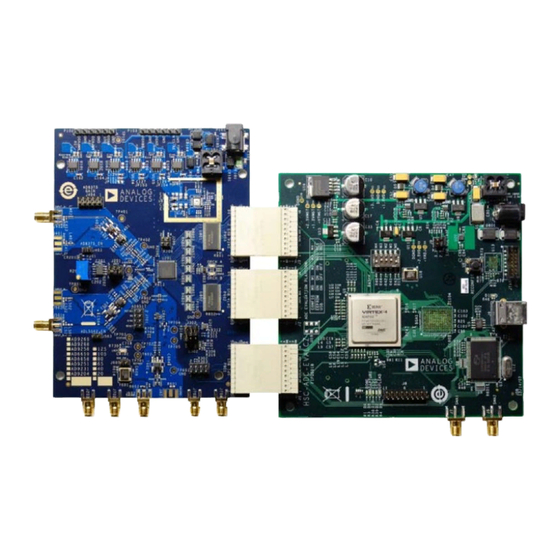
Figure 1. AD9268 and AD9269 Family Evaluation Board and HSC-ADC-EVALCZ Data Capture Board
Please see the last page for an important warning and disclaimers.
AD9269/AD6659 Analog-to-Digital Converters
TYPICAL MEASUREMENT SETUP
Evaluation Board User Guide
DOCUMENTS NEEDED
AD9650, AD9268, AD9258, AD9251, AD9231,
AD9269, or
AD6659
HSC-ADC-EVALCZ
AN-905
Application Note, VisualAnalog Converter Evaluation
Tool Version 1.0 User Manual
AN-878
Application Note, High Speed ADC SPI Control Software
AN-877
Application Note, Interfacing to High Speed ADCs via SPI
AN-835
Application Note, Understanding ADC Testing and
Evaluation
GENERAL DESCRIPTION
This document describes the AD9650, AD9268, AD9258, AD9251,
AD9231, AD9204, AD9269, and AD6659 evaluation board, which
provides all of the support circuitry required to operate these
parts in their various modes and configurations. The application
software used to interface with the devices is also described.
The AD9650, AD9268, AD9258, AD9251, AD9231, AD9204,
AD9269, and AD6659 data sheets provide additional information
and should be consulted when using the evaluation board. All
documents and software tools are available at www.analog.com/fifo.
For additional information or questions, send an email to
highspeed.converters@analog.com.
Rev. A | Page 1 of 40
data sheet
data sheet
UG-003
AD9204,
Advertisement
Table of Contents

Related Manuals for Analog Devices AD9268


Summary of Contents for Analog Devices AD9268
-
Page 1: Features
For additional information or questions, send an email to VisualAnalog highspeed.converters@analog.com. SPI controller TYPICAL MEASUREMENT SETUP Figure 1. AD9268 and AD9269 Family Evaluation Board and HSC-ADC-EVALCZ Data Capture Board Rev. A | Page 1 of 40 Please see the last page for an important warning and disclaimers. -
Page 2: Table Of Contents
Added Figure 3; Renumbered Sequentially ........5 Changes to Default Operation and Jumper Selection Settings Section ....................5 Added AD9650 Family Section, AD9268 Family Section, and AD9269 Family Section ..............5 Changes to VREF Section, Clock Circuitry for the AD9269 Family Section, and Clock Circuitry for the AD9650 and the AD9268 Family Section .............. -
Page 3: Evaluation Board Hardware
Typically, board (PCB) at P101. The 6 V supply is fused and conditioned most Analog Devices evaluation boards can accept ~2.8 V p-p or on the PCB before connecting to the low dropout linear regulators 13 dBm sine wave input for the clock. - Page 4 UG-003 Evaluation Board User Guide WALL OUTLET 100V ac TO 240V ac 47Hz TO 63Hz SWITCHING POWER SUPPLY SWITCHING POWER SUPPLY 6V dc 2A MAX SIGNAL GENERATOR 6V dc 2A MAX ANALOG FILTER SIGNAL GENERATOR ANALOG FILTER PC RUNNING VISUAL ANALOG AND SPI CONTROLLER USER SOFTWARE SIGNAL GENERATOR...
-
Page 5: Added Figure 3; Renumbered Sequentially
33Ω 0Ω AD9268/ 2V p-p AD9258 0.1µF 33Ω 66.5Ω VIN– FERRITE 0.1µF BEAD 10Ω @ 100MHz Figure 4. Default Analog Input Configuration of the AD9268 Family 0.1µF 0.1µF 33Ω VIN+ 33Ω 0Ω AD9251/ 2V p-p 22pF AD9231/ 0.1µF 33Ω AD9204 VIN–... -
Page 6: Changes To Vref Section, Clock Circuitry For The Ad9269 Family Section, And Clock Circuitry For The Ad9650 And The Ad9268 Family Section
125 MHz, jumper connection on J201 from Pin 4 through Pin 6 to Pin 3 105 MHz, or 80 MHz for the AD9268 family and 105 MHz, through Pin 4 (this connects the SENSE pin to the VREF pin). - Page 7 Evaluation Board User Guide UG-003 Switching Power Supply Install L101, L102, E116, and E117. Install R125 and R127. Optionally, the ADC on the board can be configured to use the Remove JP101 and JP103 and install JP102 and JP104. ADP2114 dual switching power supply to provide power to the Remove E103, E105, and E107 and install E104, E106, DRVDD and AVDD rails of the ADC.
-
Page 8: Changes To Evaluation Board Software Quick Start Procedures Section And Configuring The Board Section
Figure 8. VisualAnalog Window Toolbar, Collapsed Display VisualAnalog – New Canvas window. Select the template that corresponds to the type of testing to be performed (see Figure 6 where the AD9268 is shown as an example). Rev. A | Page 8 of 40... - Page 9 Evaluation Board User Guide UG-003 Figure 9. VisualAnalog, Main Window Setting Up the SPI Controller Software After the ADC data capture board setup is complete, set up the SPI controller software using the following procedure: Open the SPI controller software by going to the Start menu or by double-clicking the SPIController software desktop icon.
- Page 10 Examine the Fund Power channel only. See the appropriate part data sheet; the AN-878 reading in the left panel of the VisualAnalog Graph - AD9268 Application Note, High Speed ADC SPI Control Software; and Average FFT window (see Figure 15).
- Page 11 Evaluation Board User Guide UG-003 Troubleshooting Tips If the FFT window remains blank after Run is clicked, do the following: If the FFT plot appears abnormal, do the following: • Make sure the evaluation board is securely connected to • If you see a normal noise floor when you disconnect the the HSC-ADC-EVALCZ board.
-
Page 12: Evaluation Board Schematics And Artwork
UG-003 Evaluation Board User Guide EVALUATION BOARD SCHEMATICS AND ARTWORK Figure 17. Board Power Input and Supply Circuits Rev. A | Page 12 of 40... - Page 13 Evaluation Board User Guide UG-003 Figure 18. DUT and Related Circuits Rev. A | Page 13 of 40...
- Page 14 UG-003 Evaluation Board User Guide Figure 19. SPI Interface Circuit Rev. A | Page 14 of 40...
- Page 15 Evaluation Board User Guide UG-003 Figure 20. Channel A Input Circuits Rev. A | Page 15 of 40...
- Page 16 UG-003 Evaluation Board User Guide Figure 21. Channel B Analog Input Circuits Rev. A | Page 16 of 40...
- Page 17 Evaluation Board User Guide UG-003 Figure 22. Default Clock Path Input Circuits Rev. A | Page 17 of 40...
- Page 18 UG-003 Evaluation Board User Guide Figure 23. Optional AD9517 Clock Input Circuit Rev. A | Page 18 of 40...
- Page 19 Evaluation Board User Guide UG-003 Figure 24. Output Buffer Circuits Rev. A | Page 19 of 40...
- Page 20 UG-003 Evaluation Board User Guide Figure 25. FIFO Board Connector Rev. A | Page 20 of 40...
- Page 21 Evaluation Board User Guide UG-003 Figure 26. Top Side Rev. A | Page 21 of 40...
- Page 22 UG-003 Evaluation Board User Guide Figure 27. Ground Plane (Layer 2) Rev. A | Page 22 of 40...
- Page 23 Evaluation Board User Guide UG-003 Figure 28. Power Plane (Layer 3) Rev. A | Page 23 of 40...
- Page 24 UG-003 Evaluation Board User Guide Figure 29. Power Plane (Layer 4) Rev. A | Page 24 of 40...
- Page 25 Evaluation Board User Guide UG-003 Figure 30. Ground Plane (Layer 5) Rev. A | Page 25 of 40...
- Page 26 UG-003 Evaluation Board User Guide Figure 31. Bottom Side Rev. A | Page 26 of 40...
-
Page 27: Added Table 3; Renumbered Sequentially
Evaluation Board User Guide UG-003 ORDERING INFORMATION BILL OF MATERIALS Table 3. AD9650 Family BOM Reference Item Designator Description Value Manufacturer/Part No. C108, C109 Capacitor, ceramic, X7R, 0402 0.01 μF, 25 V Panasonic/ECJ-0EB1E103K C110 Capacitor, ceramic, X7R, 0402 2.2 nF, ±10%, 25 V Phycomp (Yageo)/0402R222K8B20D C111, C113, C519 Capacitor, ceramic, C0G, 0402... - Page 28 CR201 1.2 V micropower, precision AD1580ARTZ Analog Devices/AD1580ARTZ shunt voltage reference U202 AD822BRZ Analog Devices, Inc./AD822BRZ Single-supply, rail-to-rail low power FET-input op amp C101, C132, C133, Capacitor, ceramic, X5R, 0805 10 μF, 6.3 V Panasonic/ECJ-2FB0J106M C134, C135, C136, C145, C419, C514...
- Page 29 Evaluation Board User Guide UG-003 Reference Item Designator Description Value Manufacturer/Part No. C116, C118, C120, Capacitor, ceramic, X7R, 0402 0.1 μF, 16 V Murata/81-GRM155R71C104KA88, C122, C149, C150, Panasonic/ECJ-0EX1C104K C151, C152, C153, C154, C204, C206, C207, C208, C209, C211, C301, C302, C401, C404, C405, C406, C407, C417, C418, C420, C426,...
- Page 30 UG-003 Evaluation Board User Guide Reference Item Designator Description Value Manufacturer/Part No. J203, J402, J501, J602 CONN-PCB SMA, ST edge mount Emerson Network Power Connectivity Solutions/142-0711-821, Samtec/SMA-J-P-H-ST-EM1 J205 CONN-PCB header 4P double row Samtec/TSW-102-08-G-D J301, J701 CONN-PCB header 8-pin double row Samtec/TSW-104-08-T-D J302 CONN-PCB header...
- Page 31 Analog Devices/ADP2114_PRELIM 4 A, synchronous step-down dc-to-dc regulator Y601 ACMOS/LSTTL compatible Valpey Fisher/VFAC3BHL-XXMHZ surface-mount clock OSC Do not install. Table 4. AD9268 Family BOM Item Reference Designator Description Value Manufacturer/Part No. Not applicable PCBZ C101, C132, C133, C134, C135, C136, Capacitor, ceramic NP0 10 μF...
- Page 32 UG-003 Evaluation Board User Guide Item Reference Designator Description Value Manufacturer/Part No. C401, C402, C502, JP403, R203, R301, R302, Res film, SMD, 0402 0 Ω Panasonic/ERJ-2GE0R00X R303, R304, R424, R425, R524, R525, R526, R606, R609, R610, R611, R612, R708, R715, R723, R727, R728, R729, R803, R804 C604 Capacitor, ceramic...
- Page 33 T401, T402, T501, T502, T602 XFMR RF 1:1 (6-pin special) MABA-007159-000000 M/A-Com/ MABA-007159-000000 U101, U104, U105 IC-ADI, low dropout, ADP1708ARDZ-R7 Analog Devices, Inc./ CMOS line regulator ADP1708ARDZ-R7 U102, U106 IC-ADI, low dropout, ADP1706ARDZ-3.3-R7 Analog Devices, Inc./ CMOS line regulator ADP1706ARDZ-3.3-R7...
- Page 34 UG-003 Evaluation Board User Guide Item Reference Designator Description Value Manufacturer/Part No. Y601-80 for -80 model U201 IC clock OSC ACMOS/ 80 MHz Valpey Fisher/ LSTTL compatible VFAC3BHL-80MHZ C108, C109 Capacitor, ceramic, 10,000 pF Panasonic/ECJ-0EB1E103K multilayer, X7R 0402 C110 Capacitor, ceramic 2200 pF Phycomp (Yageo)/ CC0402KRX7R9BB222...
- Page 35 TP9, TP401, TP701, TP702, TP703, Connector-PCB White Components Corp./ TP704, TP705 TST PNT WHT TP-104-01-09 U702 IC-ADI ultrafast, SIGe ECL ADCLK905BCPZ-WP Analog Devices, Inc./ clock/data buffers ADCLK905BCPZ-WP CR201 IC-ADI 1.2 V micropower AD1580ARTZ Analog Devices, Inc./ prec. shunt voltage ref. AD1580ARTZ U202...
- Page 36 UG-003 Evaluation Board User Guide Item Reference Designator Description Value Manufacturer/Part No. C410, C510 Capacitor, ceramic NP0 22 pF Panasonic/ECU-E1H220J C705 Capacitor, ceramic, 1800 pF Panasonic/ECJ-0EB1E182K multilayer, X7R, 0402 C706 Capacitor, ceramic 0.033 μF Panasonic/0402YD333KAT2A C707 Capacitor, ceramic, 0402 1500 pF Panasonic/ECJ-0EB1H152K C722 Capacitor, ceramic...
- Page 37 M/A-Com/ (6-pin special) MABA-007159-000000 T601 XFMR RF ADT1-1WT+ Mini-Circuits/ADT1-1WT+ U101, U104, U105 IC-ADI, low dropout, ADP1708ARDZ-R7 Analog Devices, Inc./ CMOS line regulator ADP1708ARDZ-R7 U102, U106 IC-ADI, low dropout, ADP1706ARDZ-3.3-R7 Analog Devices, Inc./ CMOS line regulator ADP1706ARDZ-3.3-R7 U103 IC-ADI, low dropout, ADP1706ARDZ-1.8-R7...
- Page 38 UG-003 Evaluation Board User Guide Item Reference Designator Description Value Manufacturer/Part No. Y601-20 for -20 model U201 IC clock OSC, ACMOS/ 20 MHz Valpey Fisher/ LSTTL compatible VFAC3BHL-20MHZ C108, C109 Capacitor, ceramic, 10,000 pF Panasonic/ECJ-0EB1E103K multilayer, X7R 0402 C110 Capacitor, ceramic 2200 pF Phy Comp (Yageo)/ CC0402KRX7R9BB222...
- Page 39 TP9, TP401, TP701, TP702, Connector-PCB, Components Corp./ TP703, TP704, TP705 TST PNT white TP-104-01-09 U702 IC-ADI ultrafast, SIGe ECL ADCLK905BCPZ-WP Analog Devices, Inc./ clock/data buffers ADCLK905BCPZ-WP CR201 IC-ADI 1.2 V micropower AD1580ARTZ Analog Devices, Inc./ precision shunt voltage AD1580ARTZ reference...
- Page 40 By using the evaluation board discussed herein (together with any tools, components documentation or support materials, the “Evaluation Board”), you are agreeing to be bound by the terms and conditions set forth below (“Agreement”) unless you have purchased the Evaluation Board, in which case the Analog Devices Standard Terms and Conditions of Sale shall govern. Do not use the Evaluation Board until you have read and agreed to the Agreement.
Need help?
Do you have a question about the AD9268 and is the answer not in the manual?
Questions and answers