Table of Contents
Advertisement
Quick Links
One Technology Way • P.O. Box 9106 • Norwood, MA 02062-9106, U.S.A. • Tel: 781.329.4700 • Fax: 781.461.3113 • www.analog.com
Evaluating the AD9114/AD9115/AD9116/AD9117 and
FEATURES
Full featured evaluation board for the
AD9114/AD9115/AD9116/AD9117 (AD911x) and
AD9714/AD9715/AD9716/AD9717 (AD971x)
Includes options to evaluate
DAC only
DAC and ADL5375 quadrature modulator
DAC and op amp performance
USB interface for configuration
Internal or external power supply regulation
On-board or external clock distribution
Data pattern generator and SPI software interfaces
EQUIPMENT NEEDED
USB 2.0 port, recommended (USB 1.1 compatible)
HSC-DAC-DPG-BZ (DPG2) board
AD9114/AD9115/AD9116/AD9117 or
AD9714/AD9715/AD9716/AD9717 evaluation board
Spectrum analyzer
SOFTWARE NEEDED
DAC software suite
AD9717 software update
Please see the last page for an important warning and disclaimers.
AD9714/AD9715/AD9716/AD9717 DACs
Rev. 0 | Page 1 of 12
Evaluation Board User Guide
RELATED DOCUMENTS
Data sheets are available for both the AD911x and AD971x
products for product-specific details, including register defin-
itions. The DPG2 user guide is also available for assistance with
vector generation and loading.
GENERAL DESCRIPTION
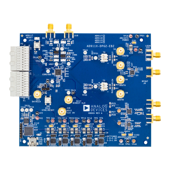
This user guide describes the AD911x and AD971x evaluation
boards, which provide all of the support circuitry required to
operate the AD911x and AD971x in their various modes and
configurations. The application software used to interface with
the devices is also described.
The AD9114/AD9115/AD9116/AD9117 and AD9714/AD9715/
AD9716/AD9717 data sheets, available at www.analog.com,
should be consulted when using the evaluation board. The
AD971x/AD911x Rev. A evaluation board operates together
with the Data Pattern Generator 2 (DPG2) and the DAC
software suite, including the AD971x/AD911x update.
The CD-ROM provided with the evaluation board includes
the installation program for all necessary software. The install
program can also be downloaded. Both methods install the
DPGDownloader program for loading vectors as well as the
AD971x/AD911x update necessary for SPI communication.
All documents and software tools are available online at
www.analog.com/dpg.
UG-073
Advertisement
Table of Contents

Related Manuals for Analog Devices AD911 Series


Summary of Contents for Analog Devices AD911 Series
-
Page 1: Features
Evaluation Board User Guide UG-073 One Technology Way • P.O. Box 9106 • Norwood, MA 02062-9106, U.S.A. • Tel: 781.329.4700 • Fax: 781.461.3113 • www.analog.com Evaluating the AD9114/AD9115/AD9116/AD9117 and AD9714/AD9715/AD9716/AD9717 DACs FEATURES RELATED DOCUMENTS Data sheets are available for both the AD911x and AD971x Full featured evaluation board for the AD9114/AD9115/AD9116/AD9117 (AD911x) and products for product-specific details, including register defin-... -
Page 2: Table Of Contents
UG-073 Evaluation Board User Guide TABLE OF CONTENTS Features ....................1 Clock Signals ..................3 Equipment Needed ................1 Input Signals...................3 Software Needed ................1 Output Signals ................4 Related Documents ..............1 Default Operation and Jumper Selection Settings ....4 ... -
Page 3: Evaluation Board Hardware
Evaluation Board User Guide UG-073 EVALUATION BOARD HARDWARE The AD911x and AD971x evaluation boards provide all of the TP13/TP8 (DVDD), with grounds at TP6, TP14, TP23, TP4, support circuitry required to operate the AD911x and AD971x and TP9. All voltages should show a reading of around 3.3 V in their various modes and configurations. -
Page 4: Output Signals
UG-073 Evaluation Board User Guide OUTPUT SIGNALS Table 1. Power Supply Jumpers The evaluation board provides the option to evaluate the analog Jumper Position for Jumper Position for Voltage Regulation Internally or Externally outputs directly from the DAC (default) or the output of the RF Power Level Regulated Voltage... - Page 5 Evaluation Board User Guide UG-073 On the evaluation board, three jumpers for each DAC select the Clock Circuitry configuration and maximum DAC current as shown in Table 3. By default, the evaluation board is set up to have a clock input on J10 that is distributed on the evaluation board via the Table 3.
- Page 6 UG-073 Evaluation Board User Guide Output Loads Table 5. Output Configuration The AD911x and AD971x provide output current. These Clock DAC Output Single-Ended Quadrature Source Default Buffered Modulator currents are converted to voltages with loading resistors. By default, the output loads are provided by on-board resistors. R15, R16 R11, R38 Alternatively, on-chip resistors can be used.
-
Page 7: Evaluation Board Software: Quick Start Procedures
See Figure 5 for the appropriate settings. Figure 3. DPG2 Board Configuration Open the AD911x or AD971x SPI software (Start > Programs > Analog Devices > AD9717 > AD971x SPI). Select the clock dividers for the data clock going to the Figure 5. Single Tone Generation DPG2, and for the clock going to the DAC. - Page 8 UG-073 Evaluation Board User Guide Once the setting of the part is selected, press the run button, at the top left side of the SPI software window. For complete descriptions of each SPI register, see the AD9114/ AD9115/AD9116/AD9117 AD9714/AD9715/AD9716/ AD9717 data sheet.
- Page 9 Evaluation Board User Guide UG-073 Section VII Section IX • This section of the SPI software configures the I and Q auxiliary This section of the SPI configures common-mode options DACs as follows: and xDAC analog gains as follows: • Enable/disable IR and QR •...
- Page 10 UG-073 Evaluation Board User Guide AD9512 Clock Chip Setup Using the AUX DACs For LO Suppression To use the clock distribution chip provided on the evaluation To completely suppress the LO when using the modulator in the board, access the control settings found on the front panel signal chain, automatic VIs can be used to sweep the codes for of the SPI front panel shown in Figure 7 and described in all of the range and offset settings of the DAC.
- Page 11 Evaluation Board User Guide UG-073 Troubleshooting above. If not, try resoldering the jumpers and test again to make sure there was not a problem with the previous connection. This section lists items to check and practices to use when Single Tone Test debugging any unexpected performance of a board.
-
Page 12: Esd Caution
Information furnished by Analog Devices is believed to be accurate and reliable. However, no responsibility is assumed by Analog Devices for its use, nor for any infringements of patents or other rights of third parties that may result from its use. Analog Devices reserves the right to change devices or specifications at any time without notice.
Need help?
Do you have a question about the AD911 Series and is the answer not in the manual?
Questions and answers