Table of Contents
Advertisement
Quick Links
OneTechnologyWay•P.O.Box9106•Norwood,MA02062-9106,U.S.A.•Tel:781.329.4700•Fax:781.461.3113•www.analog.com
AD9915 Evaluation Board for 2.5 GSPS DDS with 12-Bit DAC
FEATURES
Full-featured evaluation board for the AD9915
PC evaluation software for control and measurement of
the AD9915
USB interface
Graphic user interface (GUI) software with frequency
sweep capability and programmable modulus for
board control and data analysis
Factory tested and ready to use
PACKAGE CONTENTS
AD9915 evaluation board
AD9915PCBZ installation software CD
USB cable
Preliminary Evaluation
xxx
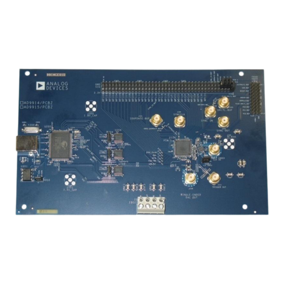
EVALUATION BOARD
Figure 1.
Rev. A | Page 1 of 14
Board User Guide
GENERAL DESCRIPTION
This user guide describes how to set up and use the
AD9915evaluation board. The AD9915 is a 2.5GSPS DDS with
a 12-bit DAC.
The evaluation board provides a graphical user interface (GUI)
for easy communication with the device along with many user-
friendly features such as the mouse-over effect.
This user guide is intended for use in conjunction with the
AD9915
data sheet.
Advertisement
Table of Contents

Related Manuals for Analog Devices AD9915


Summary of Contents for Analog Devices AD9915
-
Page 1: Features
Preliminary Evaluation Board User Guide OneTechnologyWay•P.O.Box9106•Norwood,MA02062-9106,U.S.A.•Tel:781.329.4700•Fax:781.461.3113•www.analog.com AD9915 Evaluation Board for 2.5 GSPS DDS with 12-Bit DAC FEATURES GENERAL DESCRIPTION Full-featured evaluation board for the AD9915 This user guide describes how to set up and use the AD9915evaluation board. The AD9915 is a 2.5GSPS DDS with PC evaluation software for control and measurement of a 12-bit DAC. -
Page 2: Table Of Contents
Evaluation Board User Guide TABLE OF CONTENTS Features ..................1 Device Driver Installation ............. 5 Package Contents ..............1 Starting the Software ............. 5 General Description..............1 Running the Software Under Windows 7 ......6 Evaluation Board ............... 1 ICON Description of Control Window ........7 Revision History ................ -
Page 3: Evaluation Board Hardware
ADCLK925 clock buffer to drive the AD9915 differentially. That said, a slow slew rate into the ADCLK925 Analog Devices provides a GUI for the PC; it does not provide could dramatically limit the AD9915 in-close phase noise control software for external controllers. -
Page 4: Evaluation Board Layout
External I/O Control Headers Power Supply Connections Header connectors provide a communication interface for the Provides all necessary supply voltages needed by the AD9915 AD9915 when the part is under the command of an external and the evaluation board. controller. USB Port... -
Page 5: Evaluation Board Software
3-5. STARTING THE SOFTWARE Before you start the software, make sure that the AD9915 evaluation board is powered up and connected to the PC, and the LED D200 (USB status) is on. Refer to Power Supply Connections in this user guide for correct settings. -
Page 6: Running The Software Under Windows 7
If that happens, multiple drivers can be seen able to get the software running. in this window. Select only the AD9915 Firmware Loader, and then click Next. A Hardware Installation box will then appear, just click Continue Anyway. Lastly, close the wizard by clicking Finish. -
Page 7: Icon Description Of Control Window
Evaluation Board User Guide ICON DESCRIPTION OF CONTROL WINDOW The ICON description window is built to allow ease of access clicking the Actions tab and select among the actions in the to different actions. Another way of accessing these icons is by drop-down menu. -
Page 8: Evaluation Board Software Components
Figure8.Evaluation Software Control Window The Control window provides control of the internal PLL, PLL enable is used to activate internal PLL of AD9915. The parallel port, auxiliary functions, I/O control, power down default setting of this box is disabled (check box cleared),... - Page 9 SYNC_CLK pin. Refer to Bit Descriptions for CFR2 table in AD9915 datasheet for more information. The To select the OSK function of the AD9915, select the OSK Data port mode enable allows parallel data port modulation in Enable check box.
-
Page 10: Profilemode
This allows you to synchronize multiple chips to Data Entry one master AD9915. Refer to the AD9915 data sheet for a full discussion on multichip sync functions. The Sync out Frequency is used to set the frequency generated by the enable checkbox allows activation of SYNC_OUT pin. -
Page 11: Digital Ramp Generator (Drg) Window
I/O update signal is applied or when there is a frequency, phase, or amplitude. Refer to AD9915 datasheet for profile change. The clear bit is then released. more information on DRG. -
Page 12: Programmable Modulus Window
Evaluation Board User Guide Use the Rising Step Size and Falling Step Size checkboxes to set the step size of the rising or falling ramp. The unit for these changes depending on what type of ramp is being generated. The Rising Sweep Ramp Rate and Falling Sweep Ramp Rate are used to set the time between each rising or falling step on the ramp. -
Page 13: Debug Window
Debug window is intended for debugging issues with the IOUPDATE transfers the contents of the I/O buffers to the AD9915. It can be used for all programming, but is not user- corresponding internal registers. PS0, PS1, and PS2 control friendly; this may result in improper programming of reserved the profile register pins. - Page 14 Evaluation Board User Guide The GENERIC READ/WRITE provides the interface and window which is on the left side of the REGISTER MAP. This controls for the REGISTER MAP. This can be done by only happens when the Append Transfers option is enabled. In specifying an instruction composed of the Data, the Address, addition, the current display of the GENERIC READ/WRITE the Length (Bits), and the Type of Instruction (Read/Write).
Need help?
Do you have a question about the AD9915 and is the answer not in the manual?
Questions and answers