Table of Contents
Advertisement
Quick Links
One Technology Way • P.O. Box 9106 • Norwood, MA 02062-9106, U.S.A. • Tel: 781.329.4700 • Fax: 781.461.3113 • www.analog.com
Getting Started with the AD9739-R2-EBZ Evaluation Board
WHAT'S IN THE BOX
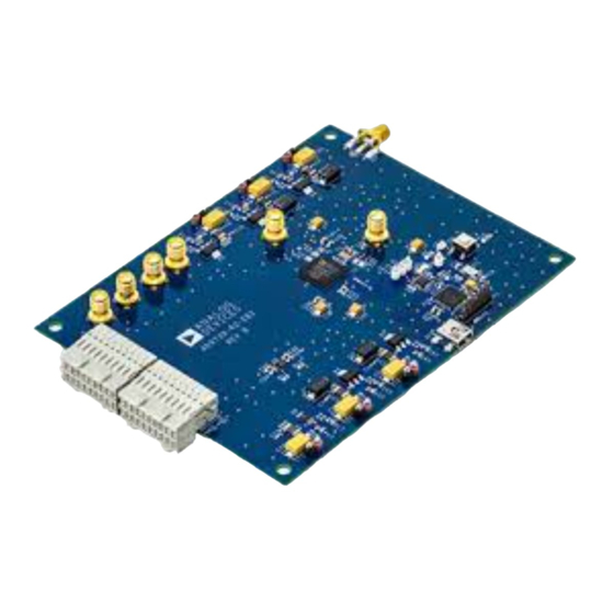
AD9739-R2-EBZ Evaluation Board
Evaluation Board CD
Mini-USB Cable
INTRODUCTION
The purpose of this document is to get the AD9739 evaluation board up and running as quickly as possible and provide guidance on how
to optimize the controllers in the part to get the optimal performance out of the AD9739.
SOFTWARE
The AD9739-R2-EBZ is designed to receive data from a DPG2. The DAC Software Suite, plus the AD9739 Update, is required for
evaluation. The DAC Software Suite is included on the Evaluation Board CD, or can be downloaded from the DPG web site at
http://www.analog.com/dpg. This will install DPGDownloader (for loading vectors into the DPG2) and the AD9739 SPI application.
HARDWARE SETUP
To operate the board, a power supply capable of +5vdc, 2A should be connected to J17. A spectrum analyzer or an oscilloscope to view
the DAC output should be connected to J1. The diagram in Figure 1 shows the location of each connection. A low jitter (< 0.5psec RMS)
sine or square wave clock source should be connected to J3. The DC level of the clock is unimportant since the clock is AC-coupled on
the evaluation board before the CLKP/N inputs. The included USB cable should be used to connect the Evaluation Board to a PC. Note
that the software described above should be installed before connecting the USB cable.
Information furnished by Analog Devices is believed to be accurate and reliable. However, no
responsibility is assumed by Analog Devices for its use, nor for any infringements of patents or other
rights of third parties that may result from its use. Specifications subject to change without notice. No
license is granted by implication or otherwise under any patent or patent rights of Analog Devices.
Trademarks and registered trademarks are the property of their respective owners.
RECOMMENDED EQUIPMENT
Low Phase Noise Sinusoidal Signal Generator or ADF4350
Evaluation Board
Spectrum Analyzer
Data Pattern Generator Series 2 (DPG2)
Figure 1
One Technology Way, P.O. Box 9106, Norwood, MA 02062-9106, U.S.A.
Tel: 781.329.4700
Fax: 781.461.3113
AD9739-R2-EBZ
Quick Start Guide
www.analog.com
©2010 Analog Devices, Inc. All rights reserved.
Advertisement
Table of Contents

Related Manuals for Analog Devices AD9739-R2-EBZ


Summary of Contents for Analog Devices AD9739-R2-EBZ
- Page 1 SOFTWARE The AD9739-R2-EBZ is designed to receive data from a DPG2. The DAC Software Suite, plus the AD9739 Update, is required for evaluation. The DAC Software Suite is included on the Evaluation Board CD, or can be downloaded from the DPG web site at http://www.analog.com/dpg.
- Page 2 This quick-start will setup a single-tone output from the AD9739 to provide a brief introduction to the part, as well as a basic functionality test. To begin, open the AD9739 SPI application (Start > Programs > Analog Devices > AD9739-R2-EBZ > AD9739 SPI).
- Page 3 Quick Start Guide AD9739-R2-EBZ Next, in the lower portion of the screen, select “1: Single Tone” as the Data Vector. The other options can be left at their default. Figure 5 After the DPG2 is correctly setup, click the Download button (...
- Page 4 Quick Start Guide AD9739-R2-EBZ Result The result of this setup should be as shown in Figure 8. Note the RF Attenuation of 20dB to accurately measure harmonics. Figure 8 Rev. A | Page 4 of 8...
- Page 5 Quick Start Guide AD9739-R2-EBZ SPI SOFTWARE The SPI software is broken up into numerous sections. Several of them are described here, as they pertain to the evaluation board. For complete descriptions of each SPI register, see the AD9739 datasheet. In the interest of continuous quality improvements, the images below may not exactly match your version of the software.
- Page 6 Quick Start Guide AD9739-R2-EBZ Mu Controller Figure 13 Mu Controller Enable: Register 0x26 Bit 0 (Set to 1 to enable the controller) Mu Controller Gain: Register 0x26 Bits 1,2 (Optimal Setting is a Gain of 1) MU Desired Phase: Desired Phase Value for Phase to Voltage Converter to Optimize Mu Controller. The optimal setting is negative 6 (max of 16) .
- Page 7 Quick Start Guide AD9739-R2-EBZ The status read back bits for the mu controller are as follows: MU_LCK: Register 0x2A bit 0 (value of 1 means the controller is locked) LST_LCK: Register 0x2A bit 1 (Value of 1 means the control lost lock)
- Page 8 RCVR Lock (Register 0x21 bit 0) This should be high if the controller is locked TRK_ON (Register 0x21 bit 3) This should be high if the controller is tracking ©2010 Analog Devices, Inc. All rights reserved. Trademarks and registered trademarks are the property of their respective owners. D00000-0-1/07...
Need help?
Do you have a question about the AD9739-R2-EBZ and is the answer not in the manual?
Questions and answers