
Related Manuals for Phoenix Model SPITFIRE


Summary of Contents for Phoenix Model SPITFIRE
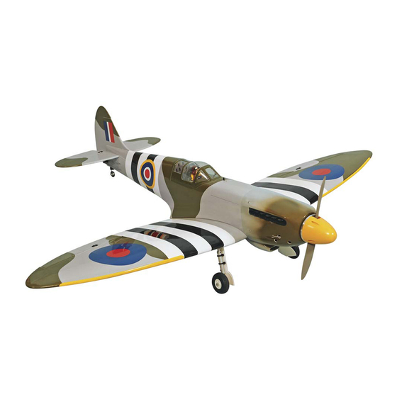
- Page 1 Instruction Manual Instruction Manual Wingspan : 1400 mm (55 inch) Length : 1240 mm (48.8 inch) Weight : 2800 g - 2900 g Engine : 40 - 46 two stroke / 52 four stroke Radio : 5 servo standard / 1 servo retract gear...
-
Page 2: Kit Contents
KIT CONTENTS: We have organized the parts as they come out of the box for better identification during assembly. We recommend that you regroup the parts in the same manner. This will ensure you have all of parts required before you begin assembly. KIT CONTENTS AIR FRAME ASSEMBLIES ELEVATOR CONTROL SYSTEM... - Page 3 Installing the aileron servo and linkage. Installing the aileron servo and linkage. Remove the covering from the top of the wing. Remove the covering from the aileron servo box. Four blocks of hard wood. Glue the two hard wood by C.A glue. 230mm Tape Install the aileron servo.
- Page 4 Using the masking tape, tape the servo lead onto the top of Secure the aileron servo box. the wing. The control horn of the aileron. Mark two holes from the control horn onto the bottom of the aileron and INLINE with the servo arm. Control horn Wing Aileron...
-
Page 5: Installing The Landing Gear
Nylon clasp Bend “L” and cut away the aileron pushrod. Attach the nylon clasp. Installing the landing gear. 120 mm One set of the landing gear. Insert the landing gear into the block and mark four holes onto the block. Metal clevis M2 Metal rod Take out the landing gear and drill four holes into the block. -
Page 6: Joining The Wing Halves
Cut away Glue the plastic part by C.A glue and make a hole. Install the wheel into the connector of the gear. Install the metal connector to the landing gear. Joining the wing halves. Center line Draw a center line. Remove the covering. - Page 7 Fix the wing and apply the trim tape to the center section Apply the trim tape to the center section on the bottom of on the top of the wing where they join. the wing where they join. Installing the landing gear servo. Install the gear servo.
- Page 8 Attach the horizontal to the fuselage and measure as photo below. Mark the shape of the fuselage onto the bottom of the Cut away the covering. horizontal. Remove the covering from the bottom of the horizontal. Glue the horizontal and fuselage by epoxy. Remove the covering from the rear of the vertical.
-
Page 9: Installing The Tail Gear
Attach the vertical to the fuselage and insert the hinge into Mark the shape of the vertical onto the top of the horizontal. the slot. Remove the covering from the top of the vertical. Glue the vertical into the fuselage by epoxy and also glue the hinge of rudder. - Page 10 Glue two nylon clasp by C.A glue into the rudder. Install the wheel and the collar into the tail gear. Install the tail gear. Secure the tail gear. Installing the elevator pushrod and linkage. The control horn of the elevator. Install the control horn onto the elevator.
- Page 11 Correct Control horn Horizontal stabilizer Elevator Wrong Control horn Horizontal stabilizer Elevator Remove the covering from both side of the fuselage. Silicone tube Silicone tube Metal clevis Install the metal clevis to the elevator pushrod and insert the Attach the metal clevis to the control horn of the left side of pushrod into the fuselage (for both side).
- Page 12 Installing the rudder pushrod and linkage. The control horn of the rudder. Install the nylon control horn. Cut away the screw if necessary. Remove the covering. Silicone tube Metal clevis Install the metal clevis. Attach the metal clevis to the control horn. Nylon clasp Install the rudder servo into the fuselage.
-
Page 13: Installing The Fuel Tank
Installing the fuel tank. Install the stopper to the tank. Secure the stopper. Install the silicone tube of the tank. Slide the fuel tank to the fuselage. Secure the fuel tank in place by rubber bank. Installing the engine. Drill a holes for throttle rod. Insert the plastic tube to the fuselage and secure it by C.A glue. -
Page 14: Installing The Throttle Servo
108 mm Attach the engine to the engine mount and mark four holes Drill four holes onto the engine mount. (this picture use the 52 OS engine four stroke). Attach the throttle rod to the arm of the carburator. Install the engine and secure it. Install the silicone exhaust (not included in the kit). -
Page 15: Installing The Switch
Attach the throttle rod into the metal connector and secure it. Installing the cowling, propeller. Screw Prepare the cowling. Install the cowling and secure it. Install the propeller. Installing the switch. Cut away the wood. Install and secure the switch. - Page 16 Switch Receiver Battery Install the radio. Installing the belly pan fairings. Prepare the belly pan fairings. Mark the belly pan fairing onto the wing. Remove the covering. Glue the belly pan fairing. Mark the belly pan fairing onto the wing. Remove the covering.
-
Page 17: Control Throws
1. Turn the airplane upside down. Attach one loop of heavy string to the engine crankshaft and one to the tail wheel wire. With the wings level, carefully lift the airplane by the string. This may require two people to make it easier. 2. - Page 18 I/C FLIGHT GUIDELINES Operate the control sticks on the When ready to fly, first extend the transmitter and check that the control transmitter aerial. surfaces move freely and in the ALWAYS land the model INTO the CORRECT directions. wind, this ensures that the model lands at the slowest possible speed.
Need help?
Do you have a question about the SPITFIRE and is the answer not in the manual?
Questions and answers