Table of Contents
Advertisement
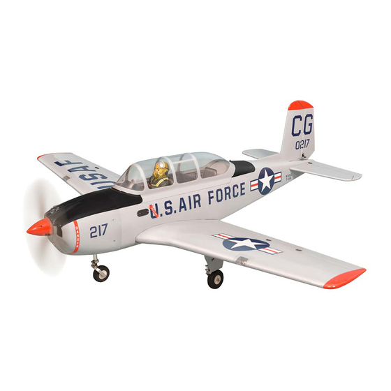
T34 MENTOR
GP/EP SIZE .91 or 15-20CC SCALE 1:5 ½ ARF
SPECIFICATION
- Wingspan: 1620mm (63.8in)
- Length: 1327mm (52.2 in)
- Flying weight: 4600-5000 g
- Wing area: 41,5 dm2
- Wing loading: 109g/dm2
- Wing type: Naca airfoils
- Covering type: Genuine ORACOVER®
- Gear type: Retract gear With CNC
Suspension Metal Struts (included)
- Spinner size: scale type 58mm (included)
- Radio: 7 channel minimum (not included)
- Servo: 8 standard servo: 2 aileron; 2 flap;
1 elevator; 1 rudder; 1steering nose; 1 throttle;
and 3 retract gear (Futaba S3170G) (not included)
- Recommended receiver battery:
4.8-6V / 2000 mAh NiMH (not included)
- Servo mount: 21mm x 42 mm
- Propeller: suit with your engine
Instruction Manual
- Engine: .91 / 2-stroke glow engine
or 15-20cc gas engine (not included)
- Motor: brushless outrunner 2200 W, 500 KV
(not included)
- Gravity CG: 115 mm (4,5 in) Back from the
leading edge of the wing, at the fuselage
- Control throw Ailerons: Low: 9mm up/down,
10% expo; High: 11mm up/down, 10% expo
- Control throw Elevators: Low: 8mm up/down,
12% expo; High: 10mm up/down, 12% expo
- Control throw Rudder: Low: 20mm right/left,
15% expo; High: 30mm right/left, 15% expo
- Control throw Flap: 15-20 mm down
- Experience level: Intermediate
- Plane type: Scale Military
RECOMMENDED MOTOR AND BATTERY SET UP
- Motor: RIMFIRE .80 (not included)
- Lipo cell: 6-10 cells / 4000 – 5500mAh
(not included)
- Esc: 60-100A (not included)
GP
EP
version
version
Advertisement
Table of Contents

Related Manuals for Phoenix Model T34 mentor


Summary of Contents for Phoenix Model T34 mentor
- Page 1 Instruction Manual version version T34 MENTOR GP/EP SIZE .91 or 15-20CC SCALE 1:5 ½ ARF SPECIFICATION - Engine: .91 / 2-stroke glow engine or 15-20cc gas engine (not included) - Wingspan: 1620mm (63.8in) - Motor: brushless outrunner 2200 W, 500 KV - Length: 1327mm (52.2 in)
-
Page 2: Tools And Supplies Needed
Please trial fit all the parts. Make sure you have the correct parts and that they fit and are aligned properly before gluing! This will assure proper assembly. The T34 MENTOR GP/EP SIZE .91 or 15-20CC SCALE TEMPORARY PIN 1:5 ½ ARF is hand made from natural materials,... -
Page 3: Installing The Aileron Servos
T34 MENTOR Instruction Manual Make certain the hinges are adequately secured with glue. If they come loose in flight accidents may result. Secure nylon hinges with instant glue, being careful not to glue the wing and airleron together. Apply instant glue (CA glue, super glue). -
Page 4: Installing The Control Horns
T34 MENTOR Instruction Manual 2 x 10mm TP Screw 2x10mm Servo extension cords. (300mm) < Top view > Warning! Set all scerws securely. If they come off during flight you will lose control of your aircraft! Cut away film only here. - Page 5 T34 MENTOR Instruction Manual 2 x 20mm TP Screw Neutral Aileron Cut off excess. Use this hole. < Bottom view > Mark the spot to attach. Bend 90 INSTALLING THE Flaps SERVOS Flaps Servo Flap < Bottom view > 13mm...
-
Page 6: Installing The Flaps Linkages
T34 MENTOR Instruction Manual 2 x 10mm TP Screw 2x10mm < Bottom view > Pay close attention here! INSTALLING THE Flaps LINKAGES Neutral 2 x 30mm Screw Flap Cut off excess. Use this hole. < Bottom view > Mark the spot to attach. -
Page 7: Installing The Main Landing Gear
T34 MENTOR Instruction Manual INSTALLING THE MAIN LANDING GEAR < Main Gear (R) > 4x4mm 3 x 8mm Button Screw 5 x 30mm Cap Screw 3x8mm 3x8mm 5mm Collar 4x4mm Set Screw Apply threadlocker (screw cement). Apply epoxy glue Cut off shaded portion Pay close attention here! <... - Page 8 T34 MENTOR Instruction Manual Main Gear (L) 3 x 20mm TP Screw Connector 3x20mm 3x20mm Retract Rod Apply threadlocker (screw cement). Cut off shaded portion Apply epoxy glue Retract and the gear is closed. Retract and the gear is opened.
- Page 9 T34 MENTOR Instruction Manual 2x10mm 2 x 10mm TP Screw SECURE The Wing To The Fuselage Attach the wings to the fuselage and secure the wing panels.
-
Page 10: Horizontal Stabilizer Installation
T34 MENTOR Instruction Manual HORIZONTAL STABILIZER INSTALLATION 1. Using a modeling knife, cut away the covering When you are sure that everything is aligned from the fuselage for the stabilizer and remove it. correctly, mix up a generous amount of 30 minute epoxy. -
Page 11: Vertical Stabilizer Installation
T34 MENTOR Instruction Manual VERTICAL STABILIZER INSTALLATION Installing the rudder using C.A glue as installing the aileron. 90 Degree Secure nylon hinges with instant glue, being careful vertical fin and rudder. Align the center line of vertical fin with rudder. - Page 12 T34 MENTOR Instruction Manual 2 x 30mm Screw Set all screws securely. If they come off during flight you will lose control of your aircraft! Remove the covering Rudder Rod Cut away film only. here. Screw 2x30mm Use this hole...
-
Page 13: Installing The Elevator Pushrod
T34 MENTOR Instruction Manual Set all screws securely. If they come off during flight you will lose control of your aircraft! Pay close attention Cut off excess. INSTALLING THE ELEVATOR PUSHROD 8. Connect the two elevator pushrod using the metal domino. - Page 14 T34 MENTOR Instruction Manual 2x16mm Elevator Rod Elevator Rod approx. 13mm Elevator Set all screws securely. If they come off during flight you will lose control of your aircraft! 3x4mm Elevator Rod Elevator Servo Bend 90 degree Cut off excess.
- Page 15 T34 MENTOR Instruction Manual INSTALLING THE nose gear retract < Wheel well > 4x4mm 3 x 20mm TP Screw 5 x 30mm Cap Screw 5mm Collar Cut off shaded portion 4x4mm Set Screw Apply threadlocker (screw cement).
- Page 16 T34 MENTOR Instruction Manual 4x4mm 2x10mm Linkage Stopper Cable rod Cable rod...
-
Page 17: Installing The Engine Mount
T34 MENTOR Instruction Manual INSTALLING THE ENGINE MOUNT 4 x 25mm Cap Screw 4mm Washer 4mm Spring Washer Hatch 4x25mm Engine Mount Apply threadlocker (screw cement). 4x25mm 6. When satisfied with the alignment of the stopper INSTALLING THE Fuel Tank... - Page 18 T34 MENTOR Instruction Manual Fuel Tank Zip tie Silicone Tube Refer to engin’s instruction manual and set up piping. INSTALLING THE THROTTLE PUSHROD SERVO 3. Apply epoxy glue to the pushrod housing where it exits the firewall and where it passes through the 1.
-
Page 19: Installing The Engine
T34 MENTOR Instruction Manual INSTALLING THE ENGINE 4x30mm Locate the long piece of wire used for the throttle pushrod. One end of the wire has been pre-bend in to a "Z" bend at the factory. This "Z" bend should be inserted into the throttle arm of the... -
Page 20: Installing The Throttle
T34 MENTOR Instruction Manual 3. Slide the adjustable metal connector / servo arm INSTALLING THE THROTTLE assembly over the plain end of the pushrod wire. Position the throttle stick and the throttle trim at 1. Install one adjustable metal connector through their lowest positions. -
Page 21: Mounting The Cowl
T34 MENTOR Instruction Manual MOUNTING THE COWL 4. While holding the cowl firmly in position, drill four 1,6mm pilot holes through both the cowl 1. Remove the muffler and needle valve assembly and the side edges of the firewall. from the engine. Slide the fiberglass cowl over the engine. -
Page 22: Installing The Spinner
T34 MENTOR Instruction Manual INSTALLING THE SPINNER Install the spinner back-plate, propeller and spinner cone. The spinner cone is held in place using two screws. The propeller should not touch any part of the spinner cone. If it dose, use a sharp modeling knife and carefully trim away the spinner cone where the propeller comes in contact with it. -
Page 23: Installing The Electric Motor
T34 MENTOR Instruction Manual Receiver Tape Tape Foam Pad Foam Pad Battery Switch Battery Receiver Must be purchased separately! INSTALLING THE ELECTRIC MOTOR 4x16mm 4x16mm 4 x 70mm Cap Screw 4 x 16mm Cap Screw White glue 4mm Washer 4x70mm... - Page 24 T34 MENTOR Instruction Manual Velcro Battery Must be purchased separately! Follow instruction manual of Motor and ESC. < Check the motor rotation > When rotating clock wise, charge the connection of 2 wires. Battery BALANCING 3. Turn the airplane upside down. Place your fingers 1.
-
Page 25: Lateral Balance
T34 MENTOR Instruction Manual 115mm (4.5 in) Aileron Control Elevator Control LATERAL BALANCE 20mm 20mm After you have balanced a plane on the C.G. You should laterally balance it. Doing this will help the airplane track straighter. Rudder Control 1. Turn the airplane upside down. Attach one loop of heavy string to the engine crankshaft and one to the tail wheel wire. - Page 26 T34 MENTOR Instruction Manual FOR YOUR RADIO INSTALLATION BASIC CONNECTION FOR AIRPLANE AND ADJUSTMENT OF SERVOS Example of connection For more information, refer to radio system instruction manual. Follow instruction manual of Engine and Battery. Flap Flap Servo Flap Flap Servo...
-
Page 27: Exploded View
EXPLODED VIEW 2x16mm 2x16mm 2x20mm 2x30mm 2x30mm 2x10mm(TP) 3x3mm 2x10mm(TP) 2x10mm(TP) 2x30mm 2x10mm 3x20mm(TP) 4x4mm 3x8mm 2x20mm 2x10mm 3x20mm(TP) 4x4mm 2x10mm(TP) Cable 2x10mm(TP) 2x10mm(TP) 2x10mm 2x10mm 4x4mm 4x4mm 3x20mm(TP) 3x8mm 4x70mm 4x30mm 4x30mm 3x10mm(TP) 4x25mm 3x15mm(TP) - Page 28 I/C FLIGHT GUIDELINES Operate the control sticks on the When ready to fly, first extend the transmitter and check that the control transmitter aerial. surfaces move freely and in the ALWAYS land the model INTO the CORRECT directions. wind, this ensures that the model lands at the slowest possible speed.
Need help?
Do you have a question about the T34 mentor and is the answer not in the manual?
Questions and answers