Table of Contents
Advertisement
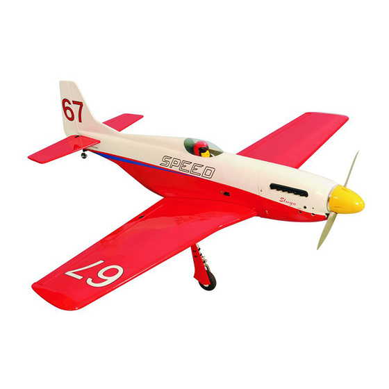
GP/EP Size 30cc SCALE 1:6 ½ ARF
SPECIFICATION
- Wingspan: 1750mm (68.9in)
- Length: 1587mm (62.5 in)
- Flying weight: 5400-6000g
- Wing area: 66.9 dm2
- Wing loading: 80g/dm2
- Wing type: Naca airfoils
- Covering type: Genuine ORACOVER®
- Gear type: Retract gear With CNC Suspension
Metal Struts and spring Tail gear (included)
- Spinner size: Plastic 95mm (included)
- Radio: 6 channel minimum (not included)
- Servo: 7 standard hi-torque servo: 2 aileron;
2 flap; 1 elevator; 1 rudder; 1 throttle; 2 retract
gear (Futaba S3170G) or 2 electric retract
(not included)
- Recommended receiver battery:
4.8-6V / 2000mAh NiMH (not included)
- Servo mount: 21mm x 42 mm
- Propeller: suit with your engine
Instruction Manual
STREGA
- Engine: 30 cc gas engine (not included)
- Motor: brushless outrunner 1600-2200 W,
450 KV (not included)
- Gravity CG: 155 mm (6.1 in) Back from the
leading edge of the wing, at the fuselage
- Control throw Ailerons: Low: 11mm up/down,
10% expo; High: 13mm up/down, 10% expo
- Control throw Elevators: Low: 11mm up/down,
12% expo; High: 13mm up/down, 12% expo
- Control throw Rudder: Low: 30mm right/left,
15% expo; High: 40mm right/left, 15% expo
- Control throw flap : Mid : 15mm down;
Landing : 20mm down
- Experience level: Intermediate
- Plane type: Scale Civilian
RECOMMENDED MOTOR AND BATTERY SET UP
- Motor: RIMFIRE .120 (not included)
- Lipo cell: 5-6 cells / 5500 – 6000mAh (not included)
- Esc: 120-160A (not included)
GP
EP
version
version
Advertisement
Table of Contents

Related Manuals for Phoenix Model STREGA


Summary of Contents for Phoenix Model STREGA
- Page 1 Instruction Manual version version STREGA GP/EP Size 30cc SCALE 1:6 ½ ARF SPECIFICATION - Wingspan: 1750mm (68.9in) - Engine: 30 cc gas engine (not included) - Length: 1587mm (62.5 in) - Motor: brushless outrunner 1600-2200 W, - Flying weight: 5400-6000g 450 KV (not included) - Wing area: 66.9 dm2...
-
Page 2: Tools And Supplies Needed
STREGA GP/EP Size 30cc SCALE 1:6 ½ ARF is thoroughly bond the covering to the wood. hand made from natural materials, every plane is unique and minor adjustments may have to be made. However, you should find the fit superior and... -
Page 3: Installing The Ailerons
STREGA Instruction Manual INSTALLING THE AILERONS 2. Apply six drops of thin CA to the top and bottom of each hinge. Do not use CA accelerator. After the CA has fully hardened, test the hinges by 1. Test fit the ailerons to the wing with the hinges. - Page 4 STREGA Instruction Manual 4. Using the thread as a guide and using masking INSTALLING THE AILERONs AND FLAPs tape, tape the servo lead to the end of the thread: carefully pull the thread out. When you SERVOS have pulled the servo lead out, remove the masking tape and the servo lead from the 1.
- Page 5 STREGA Instruction Manual Warning! Set all scerws securely. If they come off during flight you will lose control of your aircraft! Cut away film only here. Tie the string. Cut off shaded portion Pull out servo cord with string.
-
Page 6: Installing The Ailerons And Flaps Linkages
STREGA Instruction Manual INSTALLING THE AILERONs AND FLAPs LINKAGES 3 x 25mm Cap Screw 3 x 30mm Cap Screw 2 x 10mm Screw Aileron Flap < Bottom view > Neutral 2x10mm Bend 90 Mark the spot to attach. Apply threadlocker Cut off shaded portion (screw cement). -
Page 7: Installing The Main Landing Gear
STREGA Instruction Manual Aileron Flap < Bottom view > Assemble left and right sides the same way INSTALLING THE MAIN LANDING GEAR 3 x 10mm Button Screw 3 x 8mm Button Screw 5 x 40mm Cap Screw 5mm Collar 4x4mm Set Screw... - Page 8 STREGA Instruction Manual 3x10mm 3x8mm Apply instant glue (CA glue, super glue). Apply threadlocker (screw cement). Assemble left and right sides the same way...
- Page 9 STREGA Instruction Manual < Wheel well > Assemble left and right sides the same way Apply epoxy glue Cut off shaded portion Pay close attention here!
- Page 10 STREGA Instruction Manual 3 x 20mm TP Screw 2 x 10mm TP Screw 3x20mm 3x20mm Assemble left and right sides the same way...
- Page 11 STREGA Instruction Manual Must be purchased separately! Apply threadlocker (screw cement). Assemble left and right Ensure smooth, non-binding sides the same way movement when assembling < Retract gear Left. > < Retract gear Right. >...
- Page 12 STREGA Instruction Manual Apply epoxy glue Assemble left and right sides the same way...
- Page 13 STREGA Instruction Manual Apply instant glue (CA glue, super glue). Cut off shaded portion Apply epoxy glue...
-
Page 14: Horizontal Stabilizer Installation
STREGA Instruction Manual SECURE The Wing To The Fuselage 6x50mm Cap Screw Attach the wings to the fuselage and secure the wing panels. 6mm Washer 6x50mm Cut off shaded portion HORIZONTAL STABILIZER INSTALLATION When you are sure that everything is aligned correctly, mix up a generous amount of 30 minute epoxy. - Page 15 STREGA Instruction Manual Apply instant glue (CA glue, super glue). Cut off shaded portion Pay close attention here! Ensure smooth, non-binding movement when assembling...
-
Page 16: Installing Rudder And Tail Gear
STREGA Instruction Manual INSTALLING ruDDER AND TAIL GEAR 3 x 15mm TP Screw 3 x 4mm Set Screw 2.7mm Collar Secure nylon hinges with instant glue, being careful vertical fin and rudder. Align the center line of vertical fin with rudder. - Page 17 STREGA Instruction Manual 3x4mm Apply instant glue (CA glue, super glue). Apply threadlocker (screw cement).
-
Page 18: Installing The Rudder Linkages
STREGA Instruction Manual INSTALLING THE RUDDER LINKAGES 5. Thread the metal connector to the link ball. The rudder is controlled by two metal cables. 6. Center the rudder servo using the radio and Install the rudder linkages and cables as below. -
Page 19: Installing The Elevator Pushrod
STREGA Instruction Manual Set all screws securely. If they come off during flight you will lose control of your aircraft! Rudder servo Cut off shaded portion Pay close attention here Must be purchased separately! INSTALLING THE ELEVATOR PUSHROD 6. Remove the covering from the slot on the elevator. - Page 20 STREGA Instruction Manual 11. Using pliers, carefully make a 90 degree bend up at the mark made. Cut off the excess wire, leaving about 6mm beyond the bend. 12. Make the same way for the second elevator. 2x10mm 2 x 10mm Screw...
-
Page 21: Installing The Fuel Tank
STREGA Instruction Manual Elevator Servo Elevator Servo Cut off excess. Pay close attention here! INSTALLING THE Fuel Tank When the stopper assembly is installed in the tank, the top of the vent tube should rest just 1. The stopper has been pre-assembled at the below the top surface of the tank. - Page 22 STREGA Instruction Manual 8. Feed three lines through the fuel tank Do not secure the tank into place permanently compartment and through the pre-drilled hole in until after balancing the airplane. You may the firewall. Pull the lines out from behind the need to remove the tank to mount the battery in engine, while guiding the fuel tank into place.
-
Page 23: Installing The Engine
STREGA Instruction Manual INSTALLING THE ENGINE 5x100mm Cap Screw May be you also need to trim some wood from the tri-angle wood for 12x60mm Aluminum 3 x 300mm Choke rod the installation is easy. 3 x 210mm Throttle rod 5mm Spring Washer... - Page 24 STREGA Instruction Manual Throttle Lever Choke Lever DLE 30CC Silicone DLE 30CC Must be purchased separately!
-
Page 25: Installing The Throttle
STREGA Instruction Manual Electronic Ignition Zip tie Foam Pad Must be purchased separately! INSTALLING THE THROTTLE 1. Plug the throttle servo into the receiver and turn on the radio system. Check to ensure that the throttle servo output shaft is moving in the correct direction. -
Page 26: Mounting The Cowl
STREGA Instruction Manual MOUNTING THE COWL 4. While holding the cowl firmly in position, drill 1. Remove the muffler and needle valve assembly four 1,6mm pilot holes through both the cowl from the engine. Slide the fiberglass cowl over the and the side edges of the firewall. - Page 27 STREGA Instruction Manual 3x15mm Must be purchased separately!
-
Page 28: Installing The Spinner
STREGA Instruction Manual Hatch INSTALLING THE SPINNER Install the spinner back-plate, propeller and spinner cone. The spinner cone is held in place using two screws. The propeller should not touch any part of the spinner cone. If it dose, use a sharp modeling knife and carefully trim away the spinner cone where the propeller comes in contact with it. -
Page 29: Installing The Receiver And Battery
STREGA Instruction Manual INSTALLING THE RECEIVER AND BATTERY INSTALLING THE SWITCH 1. Plug the servo leads and the switch lead into the 1. The switch should be mounted on the fuselage receiver. You may want to plug an aileron side, opposite the muffler, close enough to the extension into the receiver to make plugging in the receiver so the lead will reach. -
Page 30: Installing The Electric Motor ( Ep Version )
STREGA Instruction Manual Cut off shaded portion Must be purchased separately! INSTALLING THE ELECTRIC MOTOR ( EP VERSION ) 4 x 35mm Cap Screw 4mm Washer 4x35mm 10x15mm 4x35mm 4mm Spring Washer 10x15mm Aluminum 5mm Washer White glue Must be purchased... - Page 31 STREGA Instruction Manual 16x5mm 5x100mm 12x60mm Apply threadlocker (screw cement). 5x100mm Must be purchased separately! Battery Cord Velcro Battery Must be purchased separately!
- Page 32 STREGA Instruction Manual When rotating clock wise, change the connection of 2 wires. Electric Speed Controller Must be purchased separately! Follow instruction manual of Motor and ESC. BALANCING 3. Turn the airplane upside down. Place your fingers 1. It is critical that your airplane be balanced correctly.
-
Page 33: Lateral Balance
STREGA Instruction Manual 155mm ( 6.1 in) LATERAL BALANCE CONTROL THROWS After you have balanced a plane on the C.G. 1. We highly recommend setting up a plane using the You should laterally balance it. Doing this will control throws listed. - Page 34 STREGA Instruction Manual 11mm 11mm Aileron Control 11mm 11mm Elevator Control 30mm 30mm Rudder Control 15-20mm Flap Control...
- Page 35 STREGA Instruction Manual FOR YOUR RADIO INSTALLATION BASIC CONNECTION FOR AIRPLANE AND ADJUSTMENT OF SERVOS For more information, refer to radio system instruction manual. Example of connection Follow instruction manual of Engine and Battery. Retract Gear Servo Retract Gear Servo...
- Page 36 STREGA Instruction Manual Main Gear Dimensional Detail 160.0 16.8 33.5 Tail Gear Dimensional Detail 28.0 28.0...
- Page 37 3x4mm 3x15mm(TP) 16x5mm 3x15mm(TP) 3x12mm(TP) 12x60mm 10x15mm 4x35mm 5x100mm 3x20mm(TP) 3x10mm 3x8mm 3x8mm 3x20mm(TP) 3x10mm...
- Page 38 3x25mm 3x30mm 3x20mm 3x20mm 2x10mm(TP) 2x10mm(TP) 2x10mm 3x30mm 3x30mm 3x25mm 2x10mm 2x10mm(TP) 2x10mm(TP)
- Page 39 I/C FLIGHT WARNINGS Always operate in open areas, away Keep all onlookers (especially small from factories, hospitals, schools, THE PROPELLER IS DANGEROUS children and animals) well back from buildings and houses etc. NEVER fly Keep fingers, clothing (ties, shirt the area of operation. This is a flying your aircraft close to people or built sleeves, scarves) or any other loose aircraft, which will cause serious...
- Page 40 I/C FLIGHT GUIDELINES Operate the control sticks on the When ready to fly, first extend the transmitter and check that the control transmitter aerial. surfaces move freely and in the ALWAYS land the model INTO the CORRECT directions. wind, this ensures that the model lands at the slowest possible speed.
Need help?
Do you have a question about the STREGA and is the answer not in the manual?
Questions and answers