
Related Manuals for Phoenix Model SBACH 46-55


Summary of Contents for Phoenix Model SBACH 46-55
-
Page 1: Instruction Manual
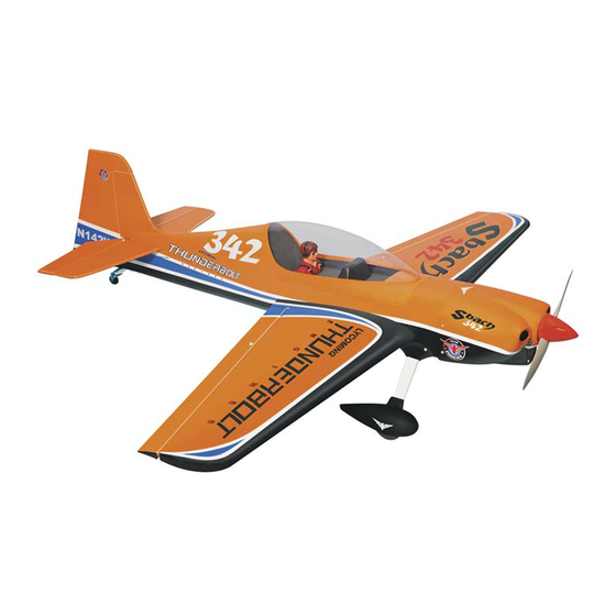
Instruction Manual Wingspan : 1405mm (55.16 in) Length : 1425mm (56.1 in) Weight : 2800gr - 3100gr Radio : 5 servo standard / 4 channel Engine : 46-55 two stroke_70-75 four stroke... -
Page 3: Kit Contents
KIT CONTENTS: We have organized the parts as they come out of the box for better identification during assembly. We recommend that you regroup the parts in the same manner. This will ensure you have all of parts required before you begin assembly. KIT CONTENTS MOTOR MOUNT ASSEMBLY MAIN GEAR ASSEMBLY... - Page 4 SAFETY PRECAUTION: INSTALLING THE AILERON SERVOS 1. Install the rubber grommets and brass eyelets • This is not a toy onto the aileron servo. • Be sure that no other flyers are using your radio frequency. 2. Turn the wing panel right side up. Using a •...
- Page 5 7. Using pliers, carefully make a 90 degree bend down at the mark made. Cut off the excess wire, leaving about 4mm beyond the bend. 8. Insert the 90 degree bend down through the hole in the servo arm. Install one nylon snap keeper over the wire to secure it to the arm.
- Page 6 HORIZONTAL STABILIZER INSTALLATION 1. Using a modeling knife, cut away the covering from the fuselage for the stabilizer and remove it. 5. Remove the stabilizer. Using the lines you just drew as a guide, carefully remove the covering from between them using a modeling knife. When cutting through the covering to remove it, cut with only enough pressure to only cut through the covering it's self.
- Page 7 7. After the epoxy has fully cured, remove the 4. Slide the vertical stabilizer back in place. Using masking tape or T-pins used to hold the a triangle, check to ensure that the vertical stabilizer in place and carefully inspect the glue stabilizer is aligned 90 degree to the horizontal joints.
- Page 8 INSTALLING THE WHEEL PANTS 1. Locate the wheel pants from the hardware bag. Mark the locations of the mounting axles onto the wheel pants. The locations of the two mounting holes are the middle of the wheel opening, on right side, left side and 10mm from the bottom of the wheel pant.
-
Page 9: Fuel Tank Installation
ENGINE INSTALLATION FUEL TANK installation INSTALLING THE THROTTLE PUSHROD HOUSING INSTALLING THE STOPPER ASSEMBLY 1. Install the engine mount into the fire wall using 1. The stopper has been pre-assembled at the 4mm x 25mm screw. factory. 2. Place the engine into the engine mount and 2. - Page 10 INSTALLING THE ELEVATOR PUSHROD Blow through one of the lines to ensure the fuel lines have not become kinked inside the fuel tank compartment. Air should flow through 1. Locate the pushrod exit slot on the right side easily. and left side of the fuselage. It is located slightly ahead and below the horizontal Do not secure the tank into place permanently stabilizer.
- Page 11 9. Plug the elevator servo into the receiver and 3. Working from inside the fuselage, slide the center the servo. Install the servo arm onto the threaded end of the remaining pushrod down servo. The servo arm should be perpendicular the inside of the fuselage until the pushrod to the servo and point toward the middle of the reaches the exit slot.
- Page 12 MOUNTING THE COWL 1. Remove the muffler and needle valve assembly from the engine. Slide the fiberglass cowl over the engine. 2. Measure and mark the locations to be cut out for engine head clearance, needle valve, muffler. Remove the cowl and make these cutouts using a rotary tool with a cutting disc and a rotary sanding drum attachment.
-
Page 13: Final Assembly
INSTALLING THE SWITCH 1. The switch should be mounted on the fuselage side, opposite the muffler, close enough to the receiver so the lead will reach. Use the face plate of the switch cut out and locate the mounting holes. 2. - Page 14 Rudder : 30mm right 30mm left 6. Properly balance the propeller. We wish you many enjoyable flights with your plane and once again thank you for your choosing a Phoenix Model's products.
-
Page 15: Metric Conversions
I/C FLIGHT WARNINGS Metric Conversions Inches x 25.4 = mm (conversion factor) 1/64" .4 mm 3/16" 4.8 mm 1" 25.4 mm 21" = 533.4 mm 1/32" .8 mm 1/4" 6.4 mm 2" = 50.8 mm 24" = 609.6 mm 1/16" 1.6 mm 3/8"... - Page 16 I/C FLIGHT GUIDELINES Operate the control sticks on the When ready to fly, first extend the transmitter and check that the control transmitter aerial. surfaces move freely and in the ALWAYS land the model INTO the CORRECT directions. wind, this ensures that the model lands at the slowest possible speed.
Need help?
Do you have a question about the SBACH 46-55 and is the answer not in the manual?
Questions and answers