
Related Manuals for Phoenix Model SENTOSA


Summary of Contents for Phoenix Model SENTOSA
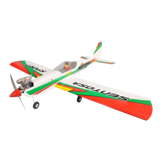
- Page 1 I n s t r u c t i o n M a n u a l Wingspan : 1600mm (62.99 inches) Length : 1420mm (55.91 inches) Weight : 2500gr - 2700gr Engine : 46 - 55 two stroke / 52 - 72 four stroke Radio : 4 channel / 5 servos standard...
-
Page 2: Kit Contents
Instruction Manual Sentosa KIT CONTENTS: We have organized the parts as they come out of the box for better identification during assembly. We recommend that you regroup the parts in the same manner. This will ensure you have all of parts required before you begin assembly... -
Page 3: Installing The Aileron Servos
This will assure proper assembly. The SENTOSA size 46-55 is hand made from natural materials, every plane is unique and minor adjustments may have to be made. However, you should find the fit superior and assembly simple. -
Page 4: Installing The Control Horns
Instruction Manual Sentosa INSTALLING THE CONTROL HORNS 4. Using the thread as a guide and using masking tape, tape the servo lead to the end of the 1. One aileron control horn in positioned on each thread: carefully pull the thread out. When you aileron. -
Page 5: Wing Assembly
Instruction Manual Sentosa WING ASSEMBLY 2. Attach the clevis to the outer hole in the control horn. Install a silicone tube on the clevis. 1. Join the wing 3. Locate one nylon servo arm, and using wire cutters, remove all but one of the arms. Using a... -
Page 6: Installing The Vertical Stabilizer
Instruction Manual Sentosa 2. Remove the covering from the bottom of the fuselage Remove the covering 3. Now, remove the vertical stabilizer and using a modeling knife, carefully cut just inside the marked lines and remove the film on both sides of the vertical stabilizer. -
Page 7: Landing Gear Installation
Instruction Manual Sentosa LANDING GEAR INSTALLATION 5. The preinstalled wire steering pushrod has a factory made Z-Bend on the front end of it. 1. There are two hardwood landing gear blocks Connect the nylon steering arm to this with one precut channel in each block in the pushrod. -
Page 8: Installing The Engine
Instruction Manual Sentosa INSTALLING THE ENGINE 3. Carefully bend the second nylon tube up at a 45 degree angle (using a cigarette lighter). This 1. Locate the long piece of wire used for the throttle tube will be the vent tube to the muffler. -
Page 9: Installing The Elevator Pushrod
Instruction Manual Sentosa 3. Working from inside the fuselage, slide the threaded end of the pushrod until it reaches the exit slot. Carefully reach in with a small screw Zip tie driver and guide the pushrod out of the exit slot. -
Page 10: Installing The Rudder Pushrod
Instruction Manual Sentosa 6. Drill two 3mm holes through the rudder using the control horn as a guide and screw the control horn in place. 7. Attach clevis to the third hole in the control horn. Install a silicone tube on the clevis. -
Page 11: Installing The Throttle
Instruction Manual Sentosa FINAL ASSEMBLY INSTALLING THE SPINNER Install the spinner back-plate, propeller and spinner cone. The spinner cone is held in place using two 3mm x 20mm wood screws. The propeller should not touch any part of the spinner cone. If it dose, use a sharp modeling knife and carefully trim away the spinner cone where the propeller comes in contact with it. -
Page 12: Installing The Switch
Instruction Manual Sentosa INSTALLING THE SWITCH 1. The switch should be mounted on the fuselage side, opposite the muffler, close enough to the 85mm receiver so the lead will reach. Use the face plate of the switch cut out and locate the mounting holes. -
Page 13: Flight Preparation Pre Flight Check
Instruction Manual Sentosa FLIGHT PREPARATION PRE FLIGHT CHECK 1. Completely charge your transmitter and receiver batteries before your first day of flying. 2. Check every bolt and every glue joint in your plane to ensure that everything is tight and well bonded. - Page 14 Instruction Manual Sentosa I/C FLIGHT WARNINGS Always operate in open areas, away Keep all onlookers (especially small from factories, hospitals, schools, THE PROPELLER IS DANGEROUS children and animals) well back from buildings and houses etc. NEVER fly Keep fingers, clothing (ties, shirt the area of operation.
- Page 15 Instruction Manual Sentosa I/C FLIGHT GUIDELINES Operate the control sticks on the When ready to fly, first extend the transmitter and check that the control transmitter aerial. surfaces move freely and in the ALWAYS land the model INTO the CORRECT directions.
Need help?
Do you have a question about the SENTOSA and is the answer not in the manual?
Questions and answers