
Related Manuals for Phoenix Model Spitfire


Summary of Contents for Phoenix Model Spitfire
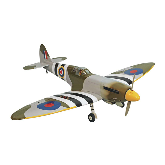
- Page 1 Instruction Manual Instruction Manual Wingspan : 1400 mm (55 inch) Length : 1240 mm (48.8 inch) Weight : 2800 g - 2900 g Engine : 40 - 46 two stroke / 52 four stroke Radio : 5 servo standard / 1 servo retract gear...
-
Page 2: Kit Contents
KIT CONTENTS: We have organized the parts as they come out of the box for better identification during assembly. We recommend that you regroup the parts in the same manner. This will ensure you have all of parts required before you begin assembly. KIT CONTENTS ELEVATOR CONTROL SYSTEM THROTTLE CONTROL SYSTEM... - Page 3 Installing the aileron servo and linkage. Installing the aileron servo and linkage. Remove the covering from the top of Remove the covering from the aileron Four blocks of hard wood. the wing. servo box. 230mm Tape Glue the two hard wood by C.A glue. Install the aileron servo.
-
Page 4: Installing The Landing Gear
Silicone tube Nylon clasp Metal clevis Install the metal clevis to the aileron Bend L and cut away the aileron Attach the nylon clasp. pushrod. pushrod. Installing the landing gear. 120 mm One set of the landing gear. Insert the landing gear into the block Take out the landing gear and drill four and mark four holes onto the block. -
Page 5: Joining The Wing Halves
Joining the wing halves. Center line Draw a center line. Remove the covering. Glue the wing joiner to the wing, using the epoxy glue. Apply the epoxy onto the wing section. Fix the wing and apply the trim tape to Apply the trim tape to the center the center section on the top of the section on the bottom of the wing... -
Page 6: Installing The Tail Gear
Remove the covering from the bottom Glue the horizontal and fuselage by Remove the covering from the rear of of the horizontal. epoxy. the vertical. Cut away the covering. Attach the vertical to the fuselage and Mark the shape of the vertical onto the insert the hinge into the slot. - Page 7 Installing the elevator pushrod and linkage. The control horn of the elevator. Install the control horn onto the Cut away the screw if necessary. elevator. Correct Control horn Horizontal stabilizer Elevator Wrong Control horn Horizontal stabilizer Elevator Make the same way for the second Remove the covering from both side of elevator.
-
Page 8: Installing The Fuel Tank
Silicone tube Clevis Metal clevis Remove the covering. Install the metal clevis. Attach the metal clevis to the control horn. Nylon clasp Install the rudder servo into the Connect the pushrod to the servo arm fuselage. and secure it by nylon clasp. Installing the fuel tank. -
Page 9: Installing The Throttle Servo
Drill four holes onto the engine mount. Attach the throttle rod to the arm of Install the engine and secure it. the carburator. Install the silicone exhaust (not included in the kit) Installing the throttle servo. Install the throttle servo. Install the metal connector to the servo Attach the throttle rod into the metal arm. - Page 10 Installing the belly pan fairings. Prepare the belly pan fairings. Mark the belly pan fairing onto the Remove the covering. wing. Glue the belly pan fairing. Mark the belly pan fairing onto the Remove the covering. wing. Glue the belly pan fairing.
-
Page 11: Control Throws
BALANCING CONTROL THROWS 1. It is critical that your airplane be balanced correctly. 1. We highly recommend setting up a plane using the Improper balance will cause your plane to lose control throws listed. control and crash. 2. The control throws should be measured at the widest THE CENTER OF GRAVITY IS LOCATED 85mm point of each control surface. - Page 12 I/C FLIGHT GUIDELINES Operate the control sticks on the When ready to fly, first extend the transmitter and check that the control transmitter aerial. surfaces move freely and in the ALWAYS land the model INTO the CORRECT directions. wind, this ensures that the model lands at the slowest possible speed.
Need help?
Do you have a question about the Spitfire and is the answer not in the manual?
Questions and answers