Table of Contents
Advertisement
Quick Links
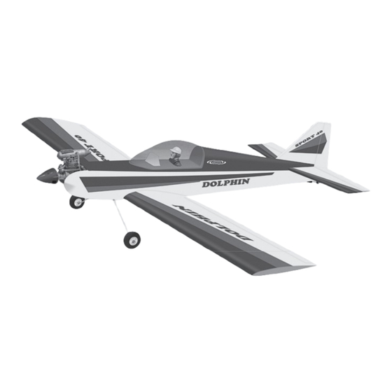
I n s t r u c t i o n M a n u a l
We wish you many enjoyable flights with your plane and one again thank you for your choosing a Phoenix Model products.
Wing span
: 1556mm [61.25 in]
Length
: 1296mm [51 in]
Wing Area
: 40.5dm2 [628sp.in]
RTF Weight
: 2381g [84oz] 5.25 lbs
Wing Loading : 73g/dm2 [24 oz / ft2]
Engine
: 40 - 46 two stroke
Radio require : 4 channel
Advertisement
Table of Contents

Related Manuals for Phoenix Model Dolphin 40


Summary of Contents for Phoenix Model Dolphin 40
- Page 1 Wing Loading : 73g/dm2 [24 oz / ft2] Engine : 40 - 46 two stroke Radio require : 4 channel We wish you many enjoyable flights with your plane and one again thank you for your choosing a Phoenix Model products.
-
Page 2: Additional Items Required
The Dolphin 40 ARF is an easy flying sport airplane, however, it may not be appropriate for some first time modelers. If you have chosen the Dolphin 40 ARF as your first airplane, we recommend you seek assistance from an experienced modeler. -
Page 3: Kit Contents
Instruction Manual Dolphin 40 KIT CONTENTS: We have organized the parts as they come out of the box for better identification during assembly. We recommend that you regroup the parts in the same manner. This will ensure you have all of parts required before you begin assembly. -
Page 4: Wing Assembly
**NOTE** Please trial fit all the parts. Make sure you have the correct parts and that they fit and are aligned properly before gluing! This will assure proper assembly. Since the Dolphin 40 ARF is hand made from natural materials, every plane is unique and minor adjustments may have to be made. -
Page 5: Aileron Servo Installation
Instruction Manual Dolphin 40 5. Once the epoxy has cured, trial fit both wing 8. When the epoxy has cured, carefully remove halves together.The center gribs should fit the masking tape from the wing. flush together with little or no gaps existing. If gaps do exist, use 220 Grit sandpaper and 9. -
Page 6: Wing Installation
Instruction Manual Dolphin 40 Also, the hole in each control horn may need to be enlarged slightly to allow the nylon clevis pin Remove the covering to be installed without binding. 5. Plug the aileron servo into the receiver and center the servo. -
Page 7: Horizontal And Vertical Stabilizer Installation
Instruction Manual Dolphin 40 6. With the bushings in place, thread the screws FIGURE # 2 into the nylon inserts in the wing mounting block in the fuselage, but do not tighten the screws completely. When satisfied with the fit of the bushings, apply a small amount of 6 Minute Epoxy to glue the bushings in place. -
Page 8: Engine Mounting
Instruction Manual Dolphin 40 Glue with epoxy 3/4" 9. Set the vertical stabilizer back in place. Using 5. Mount the muffler to the engine using the a triangle, check to ensure that it is 90 to the mounting bolts provided with your engine. -
Page 9: Fuel Tank Assembly
Instruction Manual Dolphin 40 3. Test fit the two main gear wires into the channel. When satisfied with the fit, secure Screw the wires in place using the two nylon straps and four 3*12mm sheet metal screws. If you look closely at the surface surrounding the... -
Page 10: Spinner Installation
Instruction Manual Dolphin 40 5. Push the stopper assembly into the opening 2. Most .40 size displacement engines use a 1/4'' in the tank. Adjust the assembly until the diameter crankshaft. You may need to enlarge the muffler pressure tube is resting in the top of... -
Page 11: Installing The Rudder Pushrod
Instruction Manual Dolphin 40 3. Install the clevis on the elevator pushrod. Make sure 6mm of thread shows inside the clevis. 4. The control horn should be mounted on the bottom, left side of the elevator at the leading edge, in line with the elevator pushrod. -
Page 12: Installing The Throttle
Instruction Manual Dolphin 40 12. Using a pliers, carefully make a 90 degree bend up at the mark made. Cut off excess Battery Receiver Elevator Servo wire, leaving about 8mm beyond the bend. 13. Insert the 90 degree bend up through the hole in the servo arm. -
Page 13: Receiver & Battery Installation
D) Check the throttle. Moving the throttle stick forward should open the carburetor barrel. 3. Turn the Dolphin 40 upside down and place If it does not, flip the servo reversing your fingers on the marks on top of the wing switch on your transmitter to change the and carefully lift the plane. -
Page 14: Pre-Flight Check
We recommend that you take it easy with your Dolphin 40 for the first 2) Check every bolt and every glue join in your several flights, gradually getting acquainted with... - Page 15 Instruction Manual Dolphin 40 I/C FLIGHT WARNINGS Always operate in open areas, away Keep all onlookers (especially small from factories, hospitals, schools, THE PROPELLER IS DANGEROUS children and animals) well back from buildings and houses etc. NEVER fly Keep fingers, clothing (ties, shirt the area of operation.
- Page 16 I/C FLIGHT GUIDELINES Operate the control sticks on the When ready to fly, first extend the transmitter and check that the control transmitter aerial. surfaces move freely and in the ALWAYS land the model INTO the CORRECT directions. wind, this ensures that the model lands at the slowest possible speed.
Need help?
Do you have a question about the Dolphin 40 and is the answer not in the manual?
Questions and answers