Table of Contents
Advertisement
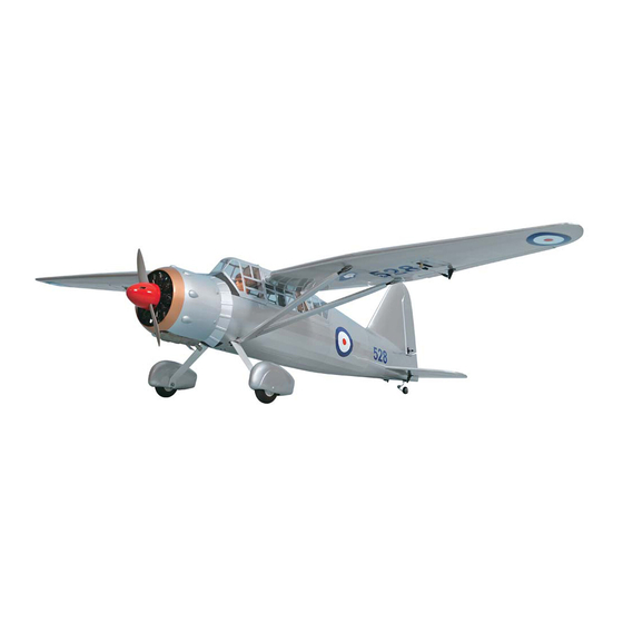
WESTLAND LYSANDER
WESTLAND LYSANDER
GP/EP Size .46-.55 Scale 1:8 ARF
SPECIFICATION
- Wingspan: 1900mm (74.8 in)
- Length: 1182mm (46.5 in)
- Flying weight: 3.4-3.6 kg
- Wing area: 43.8dm2
- Wing loading: 79g/dm2
- Covering type: Genuine ORACOVER®
- Gear type: Plate Aluminum hi-grade(included)
- Spinner size: Plastic SCALE 75mm (included)
- Radio: 4 channel minimum (not included)
- Servo: 5 standard servo: 2 aileron; 1 elevator;
1 rudder; 1 throttle (not included)
- Recommended receiver battery:
4.8-6V / 800-1200mAh NiMH (not included)
- Servo mount: 21mm x 42 mm
- Propeller: suit with your engine
- Engine: .46-.55 / 2-stroke or .52/4-stroke
glow engine (not included)
Instruction Manual
- Motor: brushless outrunner 1000-1400 W,
480 KV (not included)
- Gravity CG: 90 mm (3.5 in) Back from the
leading edge and at the WIDEST of the wing
- Control throw Ailerons: Low: 11mm up/down,
10% expo; High: 14mm up/down, 10% expo
- Control throw Elevators: Low: 12mm up/down,
12% expo; High: 14mm up/down, 12% expo
- Control throw Rudder: Low: 30mm right/left,
15% expo; High: 45mm right/left, 15% expo
- Experience level: Intermediate
- Plane type: Scale Civilian
RECOMMENDED MOTOR AND BATTERY SET UP
- Motor: RIMFIRE .46-.55 (not included)
- Lipo cell: 6 cells / 4500 – 5500mAh (not included)
- Esc: 60A (not included)
GP
EP
version
version
Advertisement
Table of Contents

Related Manuals for Phoenix Model westland lysander


Summary of Contents for Phoenix Model westland lysander
- Page 1 Instruction Manual version version WESTLAND LYSANDER WESTLAND LYSANDER GP/EP Size .46-.55 Scale 1:8 ARF SPECIFICATION - Motor: brushless outrunner 1000-1400 W, - Wingspan: 1900mm (74.8 in) - Length: 1182mm (46.5 in) 480 KV (not included) - Flying weight: 3.4-3.6 kg - Gravity CG: 90 mm (3.5 in) Back from the...
-
Page 2: Table Of Contents
Thank you for purchasing Phoenix Model products. With over 20 years experience in production and fly testing, Phoenix Model is committed to bring the best quality products and good service to customers. Along with a team of creative engineers and skilled workers, we will always accompany with customers by our great experiences, fully enthusiasm... -
Page 3: Warranty
Vacuum the parts and the work area to assemble and use this. thoroughly after working with fiberglass parts. In that Phoenix Model has no control over the final assembly or material used for final assembly, Phoenix SUGGESTION Model is not responsible for loss of use , or other incidental or consequential damages. -
Page 4: Flight Warnings
Instruction Manual WESTLAND LYSANDER FLIGHT WARNINGS ADHESIVES AND REQUIRED TOOLS When ready to fly, first extend the transmitter aerial. Thin CA Switch on the transmitter. 30-minute epoxy Switch on the receiver. 6-minute epoxy Check that the wings are correctly fitted to the Threadlocker thread locking cement fuselage. - Page 5 Instruction Manual WESTLAND LYSANDER • Officially designated AMA Air Show Teams (AST) are authorized to use devices and practices as defined within the Team AMA Program Document. (AMA Document #718.) (j) Not operate a turbine-powered aircraft, unless in compliance with the AMA turbine regulations. (AMA Document #510-A.)
-
Page 6: Preparations
Instruction Manual WESTLAND LYSANDER PREPARATIONS Use a covering iron with a covering sock on high heat to tighten the covering if necessary. Apply pressure over sheeted areas thoroughly bond the covering to the wood. INSTALLING THE AILERONS TEMPORARY PIN 1. Test fit the ailerons to the wing with the hinges. -
Page 7: Installing The Aileron Servos
Instruction Manual WESTLAND LYSANDER Make certain the hinges are adequately secured with glue. If they come loose in flight accidents may result. Secure nylon hinges with instant glue, being careful not to glue the wing and airleron together. Apply instant glue (CA glue, super glue). - Page 8 Instruction Manual WESTLAND LYSANDER Aileron Servo approx. 13mm 1.5mm 2 x 10mm TP Screw 1.5mm Warning! Set all scerws securely. If they come off during flight you will lose control of your aircraft! 2x10mm 2x10mm Cut away film only. here Supplied with the servo Pull out servo cord with string.
-
Page 9: Installing The Control Horns
Instruction Manual WESTLAND LYSANDER 3. Repeat step # 1 - # 2 to install the control horn INSTALLING THE CONTROL HORNS on the opposite aileron. 1. One aileron control horn in positioned on each aileron. Using a ruler and a pen, locate and mark the location of the control horn. - Page 10 Instruction Manual WESTLAND LYSANDER 2x20mm Aileron Silicone < Bottom view > Aileron Cut away film only. here. Bend 90 Cut off excess. < Bottom view > Assemble left and right sides the same way...
-
Page 11: Secure The Wing To The Fuselage
Instruction Manual WESTLAND LYSANDER < Right Wing > < Left Wing > SECURE The Wing To The Fuselage 3. Trim the covering from the slots for the wing alignment spares on each side of the top of the fuselage. Attach the wings to the fuselage and secure the 4. -
Page 12: Installing The Main Landing Gear
Instruction Manual WESTLAND LYSANDER Assemble left and right sides the same way INSTALLING THE MAIN LANDING GEAR 5mm Nylon Nut 5mm Nut 10x3mm Aluminum 4.7mm Collar 5mm Washer < Main Gear (R) > < Main Gear (L) > 4 x 20mm Cap Screw... - Page 13 Instruction Manual WESTLAND LYSANDER Whell pant Cut off shaded portion Assemble left and right sides the same way...
- Page 14 Instruction Manual WESTLAND LYSANDER 4x20mm Aluminum Main gear Collar Nylon Nut Washer Washer Wheel pant Assemble left and right Wheel sides the same way Cut off shaded portion...
- Page 15 Instruction Manual WESTLAND LYSANDER Collar Washer Washer Nylon Nut Assemble left and right sides the same way Apply threadlocker (screw cement).
-
Page 16: Installing The Wing Strut
Instruction Manual WESTLAND LYSANDER INSTALLING THE WING STRUT 3 x 10mm Button Screw 3 x 12mm TP Screw Wood Aluminum ball Plate of plywood Cut off shaded portion Assemble left and right sides the same way... - Page 17 Instruction Manual WESTLAND LYSANDER 3x12mm 3x10mm Assemble left and right sides the same way...
-
Page 18: Horizontal Stabilizer Installation
Instruction Manual WESTLAND LYSANDER HORIZONTAL STABILIZER INSTALLATION When you are sure that everything is aligned correctly, mix up a generous amount of 30 minute 1. Using a modeling knife, cut away the covering epoxy. Apply a thin layer to the top and bottom of from the fuselage for the stabilizer and remove it. -
Page 19: Installing Rudder And Tail Gear
Instruction Manual WESTLAND LYSANDER Apply instant glue Secure nylon hinges with instant glue, being (CA glue, super glue). careful vertical fin and rudder. Apply epoxy glue Align the center line of vertical fin with rudder. INSTALLING ruDDER AND TAIL GEAR... - Page 20 Instruction Manual WESTLAND LYSANDER Secure nylon hinges with instant glue, being careful vertical fin and rudder. Align the center line of vertical fin with rudder. Apply instant glue (CA glue, super glue). Ensure smooth, non-binding movement when assembling Apply threadlocker...
-
Page 21: Installing The Rudder Pushrod
Instruction Manual WESTLAND LYSANDER 90 Degree INSTALLING THE RUDDER PUSHROD Locate one nylon servo arm, and using wire cutters, remove all but one of the arms using a 1. Locate the pushrod exit slot on the left side of the 2mm drill bit, enlarge the third hole out from the center to accommodate the rudder pushrod wire. - Page 22 Instruction Manual WESTLAND LYSANDER Rudder Rod 2x30mm Set all screws securely. If they come off during flight you will approx. 13mm lose control of your aircraft! Hatch Must be purchased separately! Cut off excess. Cut off shaded portion Cut away film only. here.
- Page 23 Instruction Manual WESTLAND LYSANDER Rudder Servo Rudder Servo < Left side view> < Side view> < Top view> Cut off excess. Pay close attention...
-
Page 24: Installing The Elevator Pushrod
Instruction Manual WESTLAND LYSANDER INSTALLING THE ELEVATOR PUSHROD 9. Locate one nylon servo arm, and using wire cutters, remove all but one of the arms. Using a 2mm drill bit, enlarge the third hole out from the 1. Locate the pushrod exit slot on the right side center to accommodate the elevator pushrod and left side of the fuselage. - Page 25 Instruction Manual WESTLAND LYSANDER < Top view.> Domino Elevator Rod Elevator approx. 13mm Set all screws securely. If they come off during flight you will lose control of your aircraft! Elevator Rod 3x4mm Elevator Servo Domino Must be purchased Pay close attention here separately! Cut off excess.
-
Page 26: Installing The Engine Mount
Instruction Manual WESTLAND LYSANDER Hatch INSTALLING THE ENGINE MOUNT May be you also need to trim some wood from the tri-angle wood for the installation is easy. 4 x 25mm Screw 4mm Washer 4mm Spring Washer Apply epoxy glue... -
Page 27: Installing The Fuel Tank
Instruction Manual WESTLAND LYSANDER 4x25mm 4x25mm Engine Mount Apply threadlocker (screw cement). INSTALLING THE Fuel Tank 6. When satisfied with the alignment of the stopper assembly tighten the 3mm x 20mm machine screw until the rubber stopper expands and 1. The stopper has been pre-assembled at the seals the tank opening. - Page 28 Instruction Manual WESTLAND LYSANDER Foam ring Fuel Tank Silicone Tube Zip tie Refer to engin’s instruction manual and set up piping.
-
Page 29: Installing The Throttle Pushrod Servo
Instruction Manual WESTLAND LYSANDER 3. Apply epoxy glue to the pushrod housing where it INSTALLING THE THROTTLE PUSHROD SERVO exits the firewall and where it passes through the forward bulkhead. This will secure the housing in 1. Place the engine into the engine mount and align it place. -
Page 30: Installing The Engine
Instruction Manual WESTLAND LYSANDER INSTALLING THE ENGINE Locate the long piece of wire used for the throttle pushrod. One end of the wire has been pre-bend in to a "Z" bend at the factory. This "Z" bend should be inserted into the throttle arm of the... -
Page 31: Installing The Throttle
Instruction Manual WESTLAND LYSANDER Throttle Rod Must be purchased separately! INSTALLING THE THROTTLE 3. Slide the adjustable metal connector / servo arm assembly over the plain end of the pushrod wire. Position the throttle stick and the throttle trim at 1. - Page 32 Instruction Manual WESTLAND LYSANDER Throttle servo 4x4mm Adjust the throttle input (transmitter throttle stick), throttle trim movement and the carburattor opening to the suitable position and screw in the 4x4mm set screw. < Throttle Idling > < Throttle Hi >...
-
Page 33: Mounting The Cowl
Instruction Manual WESTLAND LYSANDER MOUNTING THE COWL 4. While holding the cowl firmly in position, drill four 1,6mm pilot holes through both the cowl 1. Remove the muffler and needle valve assembly and the side edges of the firewall. from the engine. Slide the fiberglass cowl over the engine. - Page 34 Instruction Manual WESTLAND LYSANDER Silicone Glue Plate of plywood Cut off shaded portion Apply epoxy glue...
-
Page 35: Installing The Spinner
Instruction Manual WESTLAND LYSANDER 3x10mm INSTALLING THE SPINNER Install the spinner back-plate, propeller and spinner cone. The propeller should not touch any part of the spinner cone. If it dose, use a sharp modeling knife and carefully trim away the spinner cone where the propeller comes in contact with it. -
Page 36: Installing The Receiver And Battery
Instruction Manual WESTLAND LYSANDER Spinner Spinner 3x12mm Propeller Must be purchased separately! INSTALLING THE SWITCH INSTALLING THE RECEIVER AND BATTERY 1. Plug the servo leads and the switch lead into the 1. The switch should be mounted on the fuselage side, opposite the muffler, close enough to the receiver. -
Page 37: Installing The Electric Motor
Instruction Manual WESTLAND LYSANDER INSTALLING THE ELECTRIC MOTOR 4 x 16mm Cap Screw 4mm Washer 4mm Spring Washer White glue 4mm Mount Nut 4 x 60mm Cap Screw 5mm Washer 4x16mm 10x35mm Aluminum 4x16mm 4x60mm 4x60mm Apply threadlocker (screw cement). - Page 38 Instruction Manual WESTLAND LYSANDER Electric Speed Controller Velcro Battery Must be purchased separately!
- Page 39 Instruction Manual WESTLAND LYSANDER Battery Electric Speed Controller < Check the motor rotation > When rotating clock wise, change the connection of 2 wires.
-
Page 40: Balancing
Instruction Manual WESTLAND LYSANDER Open and close Top Hatch BALANCING 3. If the nose of the plane falls, the plane is nose 1. It is critical that your airplane be balanced correctly. heavy. To correct this first move the battery pack Improper balance will cause your plane to lose further back in the fuselage. -
Page 41: Lateral Balance
Instruction Manual WESTLAND LYSANDER 90mm (3.5 in) CONTROL THROWS 1. We highly recommend setting up a plane using the control throws listed. 2. The control throws should be measured at the widest point of each control surface. LATERAL BALANCE 3. Check to be sure the control surfaces move in After you have balanced a plane on the C.G. -
Page 42: For Your Radio Installation
Instruction Manual WESTLAND LYSANDER 11mm 11mm Aileron Control 12mm 12mm Elevator Control 30mm 30mm Rudder Control FOR YOUR RADIO INSTALLATION BASIC CONNECTION FOR AIRPLANE AND ADJUSTMENT OF SERVOS Example of connection For more information, refer to radio system instruction manual. -
Page 43: Main Gear Dimensional Detail
Instruction Manual WESTLAND LYSANDER Main Gear Dimensional Detail 29.0 Ø5.4 160.0 Tail Gear Dimensional Detail 90.3 32.5 21.5 57.8... -
Page 44: Decoration
Instruction Manual WESTLAND LYSANDER DECORATION < Bottom view > < Top view > < Side view > < Side view >... - Page 45 4x16mm 4x16mm 3x10mm(TP) 4x60mm 10x35mm 4x60mm 3x12mm(TP) 75mm 3x4mm 4x20mm 4x20mm 75mm 3x25mm 3x25mm 4x25mm 4x25mm...
-
Page 46: Exploded View
EXPLODED VIEW 2x16mm 2x16mm 2x20mm 2x10mm(TP) 2x30mm 3x4mm 2x10mm 4x4mm 2x20mm 2x10mm(TP) - Page 47 I/C FLIGHT WARNINGS Always operate in open areas, away Keep all onlookers (especially small from factories, hospitals, schools, THE PROPELLER IS DANGEROUS children and animals) well back from buildings and houses etc. NEVER fly Keep fingers, clothing (ties, shirt the area of operation. This is a flying your aircraft close to people or built sleeves, scarves) or any other loose aircraft, which will cause serious...
- Page 48 I/C FLIGHT GUIDELINES Operate the control sticks on the When ready to fly, first extend the transmitter and check that the control transmitter aerial. surfaces move freely and in the ALWAYS land the model INTO the CORRECT directions. wind, this ensures that the model lands at the slowest possible speed.
Need help?
Do you have a question about the westland lysander and is the answer not in the manual?
Questions and answers