Advertisement
Quick Links
Download this manual
See also:
Instruction Manual
Instruction Manual
Instruction Manual
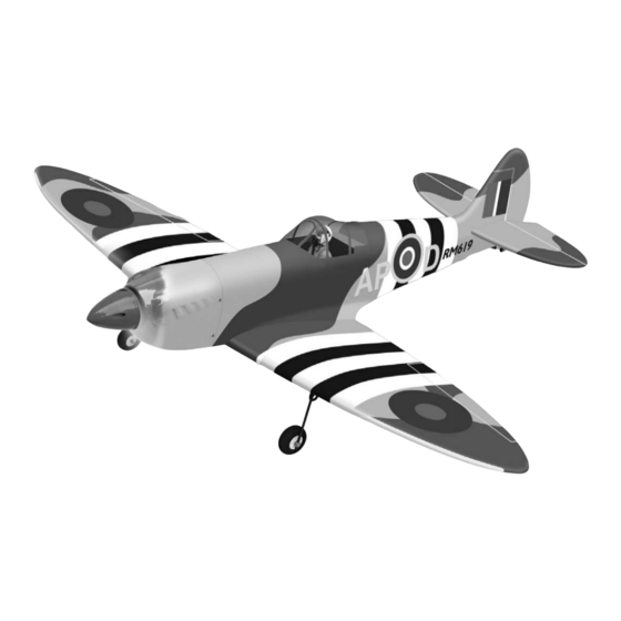
Wingspan : 1543mm (60.75 inch)
Length
Weight
g
Engine
Radio
: 1350mm (53.15 inch)
: 3200gr - 3600gr
: 61 two stroke / 70 four stroke
: 6 servo / 6 channel
Advertisement

Related Manuals for Phoenix Model Spitfire


Summary of Contents for Phoenix Model Spitfire
- Page 1 Instruction Manual Instruction Manual Wingspan : 1543mm (60.75 inch) Length : 1350mm (53.15 inch) Weight : 3200gr - 3600gr Engine : 61 two stroke / 70 four stroke Radio : 6 servo / 6 channel...
-
Page 2: Kit Contents
KIT CONTENTS: We have organized the parts as they come out of the box for better identification during assembly. We recommend that you regroup the parts in the same manner. This will ensure you have all of parts required before you begin assembly. KIT CONTENTS AIR FRAME ASSEMBLIES AILERON CONTROL SYSTEM... - Page 3 Please trial fit all the parts. Make sure you have the correct parts and that they fit and are aligned properly before gluing! This will assure proper assembly. The SPITFIRE is hand made from natural materials, TEMPORARY PIN every plane is unique and minor adjustments may TO KEEP HINGE have to be made.
-
Page 4: Installing The Aileron Servos
INSTALLING THE AILERON SERVOS 5. Place the aileron servo tray / hatch into the servo box on the bottom of the wing and drill 1. Install the rubber grommets and brass eyelets 1,6mm pilot holes through the tray and the onto the aileron servo. - Page 5 INSTALLING THE AILERON LINKAGES INSTALLING THE LANDING GEAR 1. Install the gear servo into the servo tray in the 1. Working with the aileron linkage for now, thread fuselage. one nylon clevis at least 14 turns onto one of the 1.7mm x 180mm threaded wires. 2.
- Page 6 5. Install and secure the retract gear into the wing. 6. Secure the wooden plate. Machine screw 8. Install the adjustable servo connector to the servo arm of the servo retract gear. Aluminum collar 9. Slide both wing to the fuselage, attach both metal pushrod to the servo arm of the servo retract gear.
- Page 7 10.Secure the wing to the fuselage using the plastic screws. Plastic screw Cowl (head) INSTALLING THE HORIZONTAL STABILIZER 1. Using a modeling knife, cut away the covering from the fuselage for the stabilizer and remove Retract and the gear is opened. 2.
- Page 8 Glue the hinges by C.A glue 4. When you are sure that everything is aligned correctly, mix up a generous amount of 30 INSTALLING THE RUDDER minute epoxy. Apply a thin layer to the bottom and to the top of the stabilizer mounting area and to the stabilizer mounting platform sides in Repeat step 1 - step 6 from the installing aileron the fuselage.
- Page 9 ENGINE INSTALLATION Installing the engine mount Install the engine mount using 4 screw 4mm x 25mm INSTALLING THE TAIL WHEEL 1. Using the knife cut away the wood from the bottom of the rudder and slide the two nylon clasps into the slot. Using C.A glue the nylon clasps as shown.
- Page 10 INSTALLING THE ENGINE Locate the long piece of wire used for the throttle pushrod. One end of the wire has been pre-bend in to a "Z" bend at the factory. This "Z" bend should be inserted into the throttle arm of the engine when the engine is fitted onto the engine mount.
- Page 11 To carburator To muffler To vent Tube SERVO INSTALLATION INSTALLING THE FUSELAGE SERVOS 1. Install the rubber grommets and brass collets into the elevator, rudder and throttle servos. Test fit the servos into the servo tray. Trim the tray if necessary to fit your servos 2.
- Page 12 8. Locate one nylon servo arm, and using wire Elevator servo cutters, remove all but one of the arms using a Metal domino 2mm drill bit, enlarge the third hole out from the center to accommodate the rudder pushrod wire. 9.
- Page 13 Motor control servo 7. Install the muffler. Connect the fuel and pressure MOUNTING THE COWL lines to the carburator, muffler and fuel filler valve. Tighten the screws completely. 1. Remove the muffler and needle valve FINAL ASSEMBLY assembly from the engine. Slide the fiberglass cowl over the engine.
- Page 14 Do not permanently secure the receiver and battery until after balancing the model. 100mm 4. Using a 2mm drill bit, drill a hole through the side of the fuselage, near the receiver, for the antenna to exit. INSTALLING THE SWITCH 1.
- Page 15 FLIGHT PREPARATION PRE FLIGHT CHECK 1. Completely charge your transmitter and receiver batteries before your first day of flying. 2. Check every bolt and every glue joint in your plane to ensure that everything is tight and well bonded. 3. Double check the balance of the airplane 4.
- Page 16 I/C FLIGHT GUIDELINES Operate the control sticks on the When ready to fly, first extend the transmitter and check that the control transmitter aerial. surfaces move freely and in the ALWAYS land the model INTO the CORRECT directions. wind, this ensures that the model lands at the slowest possible speed.
Need help?
Do you have a question about the Spitfire and is the answer not in the manual?
Questions and answers