Emerson Fisher 4320 Instruction Manual
Wireless position monitor
Hide thumbs
Also See for Fisher 4320:
- Instruction manual (70 pages) ,
- Instruction manual supplement (4 pages) ,
- Instruction manual (24 pages)
Table of Contents
Advertisement
Quick Links
Download this manual
See also:
Instruction Manual
Instruction Manual
D103392X012
Fisherr 4320 Wireless Position Monitor
Contents
. . . . . . . . . . . . . . . . . . . . . . . . . . . . . . . . .
. . . . . . . . . . . . . . . . . . . . . . . . . . . . .
. . . . . . . . . . . . . . . . . . . . . . . . . . . . . . . . .
. . . . . . . . . . . . . . . . . . . . . . . . . . . . . . . .
. . . . . . . . . . . . . . . . . . . . . . . . . . . . . . .
. . . . . . . . . . . . . . . . . . . . . . . . .
. . . . . . . . . . . . . . . . . . . . . . . . .
. . . . . . . . . . . . . . . . . . . . . . . . . . . . . . . . . .
. . . . . . . . . . . . . . . . . . . . . . . . . . . .
. . . . . . . . . . . . . . . . . . . . . . . . . . . . . .
. . . . . . . . . . . . . . . . . . . . . . . . . . . . . . . . .
. . . . . . . . . . . . . . . . . . . . . . . . . .
. . . . . . . . . . . . . . . . . . . . . . . . . . . . . . . . .
. . . . . . . . . . . . . . . . . . . . . . . . . . . . . . .
. . . . . . . . . . . . . . . . . . . . . . . . . . . . .
. . . . . . . . . . . . . . . . . . . . . . . . . . .
. . . . . . . . . . . . . . . . . . . . . . . . . . . . . . .
. . . . . . . . . . . . . . . . . . . . . . . . . . . . . .
Introduction
Scope of Manual
This instruction manual includes specifications, installation, initial setup, configuration, operation, troubleshooting,
and maintenance information for the Fisher 4320 wireless position monitor.
www.Fisher.com
. . . . . . . . . . . . . . .
. . . . . . . . . . . . .
. . . . . . . . . . . . . . . .
. . . . . . . . .
. . . . . . . . . . . . . . . . . . .
. . . . . . . . . . . . . . . . . . . . . .
. . . . . . . . . . . . . . .
. . . . . . . . . . . . . . . . . .
. . . . . . . . . . . . . . . . . . . . .
. . . . . . . . . . . . . . . .
. . . . . . . . . . . . . . .
. . . . . . . . . . . . . . . . . . . . .
. . . . . . . . . . . . . . . .
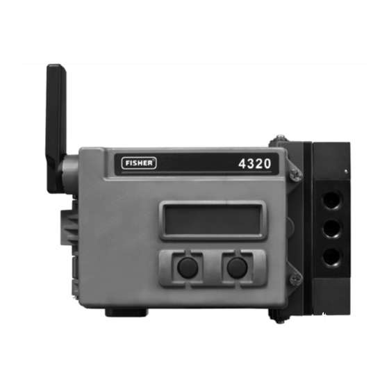
Figure 1. Fisher 4320 Wireless Position Monitor
1
1
2
2
2
2
5
6
6
8
9
9
9
11
14
W9634-2
15
16
18
18
19
19
20
20
20
20
20
21
22
23
23
. . . . . . . . . . . . . . . . . . . . . . . . . . . . . . . . . . . . . . .
23
4320 Position Monitor
. . . . . . . . . . . . . . . . . . . . . . . . . . . . .
. . . . . . . . . . . . . . . . . . . . . . . . . . .
. . . . . . . . . . . . . . . . . . . . . . . . . . .
. . . . . . . . . . . . . . . . . . . . . . . .
. . . . . . . . . . . . . . . . . . . . . . . . . . . . . . . .
. . . . . . . . . . . . . . . . . . . .
. . . . . . . . . . . . . . . . . . . . .
. . . . . . . . . . . . . . . . . . . . . . .
. . . . . . . . . . . . . . . . .
. . . . . . . . . . . . . . . . . . . . . . . . . . . . . . .
. . . . . . . . . . . . . . . . . . . . . . . . . . . . .
. . . . . . . . . . . . . . . . . . . . . . . . . . .
February 2013
26
32
35
38
39
40
40
40
40
41
41
. . . . . . . . .
41
43
43
Advertisement
Table of Contents

Related Manuals for Emerson Fisher 4320


Summary of Contents for Emerson Fisher 4320
-
Page 1: Table Of Contents
......Introduction Scope of Manual This instruction manual includes specifications, installation, initial setup, configuration, operation, troubleshooting, and maintenance information for the Fisher 4320 wireless position monitor. www.Fisher.com... -
Page 2: Description
To avoid personal injury or property damage, it is important to carefully read, understand, and follow all of the contents of this manual, including all safety cautions and warnings. If you have any questions about these instructions, contact your Emerson Process Management sales office before proceeding. - Page 3 Instruction Manual 4320 Position Monitor D103392X012 February 2013 Table 1. Specifications Available Mountings Output Communication Signal Quarter‐turn rotary‐shaft 2.4 Ghz, DSSS, WirelessHART sliding‐stem or Maximum 10 dBm EIRP at 2.46 GHz, linear applications 10 mW EIRP at 2.46 GHz Can also be mounted on other actuators that comply Wireless Classifications with IEC 60534‐6‐1, IEC 60534‐6‐2, VDI/VDE 3845 and NAMUR mounting standards...
- Page 4 2. Due to the combustible nature of the lithium content, the power module has special installation, operation, storage, and/or shipping requirements. Observe all warnings included with the power module before installing, operating, storing, or shipping. Contact your Emerson Process Management sales office if additional information is needed.
-
Page 5: Educational Services
(mA) Educational Services For information on available courses for the 4320 wireless position monitor, as well as a variety of other products, contact: Emerson Process Management Educational Services, Registration P.O. Box 190; 301 S. 1st Ave. Marshalltown, IA 50158-2823 Phone: 800-338-8158 or... -
Page 6: Installation
Instruction Manual 4320 Position Monitor February 2013 D103392X012 Installation WARNING Before mounting the 4320 wireless position monitor: D Always wear protective clothing, gloves, and eyewear when performing any installation procedures to avoid personal injury or property damage. D Check with your process or safety engineer for any additional measures that must be taken to protect against process media. - Page 7 Resetting Power Module Variables procedure found on page 41. 7. Close the cover and tighten the instrument cover screws. Figure 2. Fisher 4320 Wireless Position Monitor with Battery Sourced Power Modules J1 PWR TERMINAL ELECTRICAL CONNECTION SCREWS (4 TOTAL)
-
Page 8: Installing External Power Option
Instruction Manual 4320 Position Monitor February 2013 D103392X012 Installing External Power Option Refer to figure 4 and 5 when installing the wiring. 1. Loosen the two instrument screws and open the cover. 2. Install the cable gland assembly O-ring on the cable gland threads; push it on as far it will go, as shown in figure 4. 3. -
Page 9: Network Setup
Instruction Manual 4320 Position Monitor D103392X012 February 2013 Network Setup The 4320 should have wireless network parameters configured prior to becoming part of a wireless network. All WirelessHART devices within a network have two network parameters that are the same; the Network ID and the Join Key. - Page 10 Note Selecting the Emerson Specific command results in setting PV, SV, TV, and QV values plus the additional device status information. 6. Remove the leads from the 4320 and close the cover. 7. Install the 4320 on monitored equipment and/or verify the 1420 gateway.
-
Page 11: Hazardous Area Classifications And Special Instructions For "Safe Use" And Installations In Hazardous Locations
Special instructions are listed by approval. Note This information supplements the nameplate markings affixed to the product. Always refer to the nameplate itself to identify the appropriate certification. Contact your Emerson Process Management sales office for approval/certification information not listed here. WARNING Failure to follow these conditions of “safe use”... - Page 12 Instruction Manual 4320 Position Monitor February 2013 D103392X012 ATEX Intrinsically Safe II 1 G Battery Sourced Power Module External Power Option Ex ia IIC T3/T4/T5 Ga Ex ia IIC T5(Tamb ≤ 80_C) Ga Enclosure: Type 4X and IP66 Enclosure: Type 4X and IP66 Special Conditions of Use The apparatus must be only connected to certified intrinsic safety equipment and this combination must be compatible regarding intrinsic safety rules.
- Page 13 Instruction Manual 4320 Position Monitor D103392X012 February 2013 Figure 8. Loop Schematic for External Power Option INSTALLATION MUST BE IN ACCORDANCE WITH THE NATIONAL WIRING PRACTICES OF THE COUNTRY IN USE. BARRIERS MUST BE CONNECTED PER MANUFACTURE'S INSTALLATION INSTRUCTIONS. INTRINSICALLY SAFE APPARATUS MAY BE CONNECTED TO ASSOCIATED APPARATUS NOT SPECIFICALLY EXAMINED IN SUCH COMBINATION.
-
Page 14: Valve / Actuator Mounting
Instruction Manual 4320 Position Monitor February 2013 D103392X012 Valve / Actuator Mounting If ordered as a part of a control valve assembly, the factory will mount the wireless position monitor on the actuator and calibrate the instrument. If you purchased the wireless position monitor separately, you will need a mounting kit to mount the wireless position monitor on the actuator. -
Page 15: Sliding-Stem (Linear) Actuators (E.g. Fisher 667)
Instruction Manual 4320 Position Monitor D103392X012 February 2013 Figure 9. Travel Range VALID TRAVEL RANGE 25 mm (1 INCH) SHOWN MAGNET ASSEMBLY (ATTACHED TO VALVE STEM) W9635-2 There are a variety of mounting brackets and kits that are used to mount the 4320 to different actuators. However, despite subtle differences in fasteners, brackets, and connecting linkages, the procedures for mounting can be categorized as follows: D Linear or sliding‐stem actuators with up to 210 mm (8.25 inch) travel... -
Page 16: Guidelines For Mounting On Quarter-Turn (Rotary-Shaft) Actuators
Instruction Manual 4320 Position Monitor February 2013 D103392X012 1. Attach the mounting bracket to the actuator. 2. Loosely attach the feedback pieces and magnet assembly to the valve stem connector. Do not tighten the fasteners because fine adjustment is required. CAUTION Do not install a magnet assembly that is shorter than the physical travel of the actuator. - Page 17 Instruction Manual 4320 Position Monitor D103392X012 February 2013 2. Install the mounting bracket on the actuator. 3. Attach the wireless position monitor to the mounting bracket using the 4 mounting bolts, as shown in figure 13. 4. Check for clearance between the magnet assembly and the positioner feedback slot. 5.
-
Page 18: Communication Connections
Faster sampling affects power module life as shown in figures 16 and 17. Refer to Advanced Wireless Reporting (Report By Exception and Delayed Trigger Reporting) on page 27 for additional information on faster sampling. Consult the Emerson Smart Wireless Gateway information for details on network size, available at http://www2.emersonprocess.com/en-US/brands/rosemount/Wireless/Wireless-Gateway/Pages/index.aspx... -
Page 19: Basic Setup
Instruction Manual 4320 Position Monitor D103392X012 February 2013 Figure 16. Standard Power Module Life Versus Figure 18. Number of Sub-Devices Impact on Power Update and Sample Rate Module Life NUMBER OF SUB-DEVICES UPDATE RATE (SECONDS) STANDARD CONTINUOUS UPDATE RATE EXTENDED NOTE: 60 SECOND UPDATE RATE, 0.5 SECOND SAMPLE RATE CONSTANT TEMPERATURE OF 25_C (77_F). -
Page 20: Identifying Device Revision
The two buttons on the LCD display (see figure 20) are used to activate the display when the LCD is in the sleep state (blank or off). The buttons can be pressed alone or simultaneously. The Emerson logo will display when the LCD is activated from a HART “squawk”... -
Page 21: Network
Instruction Manual 4320 Position Monitor D103392X012 February 2013 The remaining life value of the power module is an estimate. The life span of the power module is affected by many operating conditions, including: The update or burst rate of the 4320 wireless position monitor. The number of devices operating through this device to the gateway and their update or burst rates. -
Page 22: Calibration
Instruction Manual 4320 Position Monitor February 2013 D103392X012 Press SELECT to display the NETWORK ID configured in the device. Press NEXT to show the current network operational state: SEARCHING—the device is waiting to detect the presence of a wireless network with the same Network ID and join key. NEGOTIATING—the presence of a wireless network with the same network parameters has been detected and the device is attempting to join the network. -
Page 23: Setup
Instruction Manual 4320 Position Monitor D103392X012 February 2013 Applying calibration points without changing the valve position will result in the calibration attempt being unused or discarded. The calibration status will be displayed: SUCCESS—indicates that the calibration procedure was successful. SPAN HI—indicates that a problem with the high end of travel or rotation was observed. Check the mounting and magnet assembly placement and re‐attempt calibration. - Page 24 Instruction Manual 4320 Position Monitor February 2013 D103392X012 Figure 21. Field Communicator Menu Tree—Overview 1‐3 Primary Purpose Variables 1 Position Field Communicator 2 Position Quality 3 Switch States 1 Offline Overview 4 Switch States Quality 2 Online 1 Device Status 5 Update Rate 3 Frequency Device 2 Comm Status 4 Utility 3 Primary Purpose Variable 1‐5-2 4 Join Device to Network...
- Page 25 Instruction Manual 4320 Position Monitor D103392X012 February 2013 Device Information D Identification—includes general device and functional assignment information, including instrument manufacturer, device tags, model, unique ID, description, message, polling address, and commissioning date. D Revisions Universal—indicates the HART Universal Revision. Device—indicates the revision number of the software for communication between the Field Communicator and the instrument.
-
Page 26: Configure
Instruction Manual 4320 Position Monitor February 2013 D103392X012 Configure Refer to figure 22 for the Configure menu tree. Figure 22. Field Communicator Menu Tree—Configure 2‐2‐1 Guided Setup Wireless 2‐1 1 Device Setup 1 Transmit Power 2 Alert Setup 2 Change Radio Power 3 Wireless Setup 3 Wireless Mode Field Communicator 2‐2... - Page 27 Instruction Manual 4320 Position Monitor D103392X012 February 2013 Manual Setup D Wireless Transmit Power—indicates the radiated power setting of the radio. (Read-only) Change Radio Power—select the radiated power setting of the radio: High or Low. Wireless Mode—displays the current communication state of the device, or its ability to provide information to the network.
- Page 28 Instruction Manual 4320 Position Monitor February 2013 D103392X012 and the data is sampled and published at a fast rate when there is a significant change in the monitored trigger variable. A slower “default” rate is used when the trigger conditions are not met. This feature results in lower energy consumption by the device, as there are fewer data transmissions.
- Page 29 If an Emerson Gateway is in use, the 'Emerson-Specific' choice can be used. It combines the 4 Dynamic Variables and the Additional Status in one message. However, it does not include the Loop Current or PV %Range variables. If the control system requires PV %Range and Loop Current, make sure that these two variables are included in a message configured for 'Selected Device Variables'.
- Page 30 Instruction Manual 4320 Position Monitor February 2013 D103392X012 Another alternative is to add an additional message configured for 'PV %Range, Loop Current' (HART command 2) but configure it for a slow update rate, since these variables contain no useful data in this device – they are published only because some masters will not work properly unless they are present.
- Page 31 Reset Module Data—used to reset the life expectancy of the battery. This is done when replacing the power module. Note Contact your Emerson Process Management sales office if a replacement power module is required. Do not re‐use power modules from other units.
-
Page 32: Service Tools
Instruction Manual 4320 Position Monitor February 2013 D103392X012 Slow Responding Alert Trip Point Suppress 'Open Alert' Suppress 'Partially Open Alert' Suppress 'Closed Alert' Calibration Calibration Status—indicates if the position monitor has been calibrated. Calibration Date—indicates when the instrument was last calibrated. Sensor Calibration—allows you run a calibration on the instrument. - Page 33 Instruction Manual 4320 Position Monitor D103392X012 February 2013 Variables D Variable Summary Process Position—indicates the position of the monitored equipment (e.g. valve) as a percent of travel or span. Switch States—dictates the position of the monitored equipment (e.g. valve) as a discrete value; OPEN, CLOSED, or PARTIALLY OPEN.
- Page 34 If the message is enabled, you can view a snapshot of the values that would be published in the message, based on the current device states. Maintenance D Squawk—select Squawk to command the device to display the Emerson logo to assist a technician in locating it. Specify the number of repeats at approximate 5 minutes each. Note The Squawk function is unavailable when the temperature is too low for a usable display, or if the LUI is currently in use for a local function.
-
Page 35: Accessing Features
Instruction Manual 4320 Position Monitor D103392X012 February 2013 D Calibration—used to set travel or rotation end points. Calibration Status—indicates if the position monitor has been calibrated. Calibration Date—indicates when the instrument was last calibrated. Sensor Calibration—allows you run a calibration on the instrument. Follow the prompts on the Field Communicator to set the zero percent (Closed) and 100 percent (Open) points to calibrate the instrument. - Page 36 Instruction Manual 4320 Position Monitor February 2013 D103392X012 Figure 24. Change Update Rate in AMS Wireless Figure 25. Setting Trip Point in AMS Wireless Configurator and AMS Device Manager Configurator and AMS Device Manager BROADCAST INFORMATION TAB MANUAL SETUP LIMIT SWITCH TAB MANUAL SETUP UPDATE DETAILS...
- Page 37 For information on using Modbus or OPC with the 4320 wireless monitor refer to 4310/4320 Wireless Position Monitor OPC System Integration Guide (D103530X012) or 4310/4320 Wireless Position Monitor Modbus System Integration Guide (D103529X012), available from your Emerson Process Management sales office or at www.Fisher.com.
-
Page 38: Principle Of Operation
Select Online, Service Tools, Maintenance, then Squawk from the Find tab to access Find with LCD, as shown in figure 28. The squawk function displays the Emerson Logo steadily for 5 minutes on the local display of the device. You may select how many time the squawk is repeated at 5 minutes per request. -
Page 39: Maintenance
Instruction Manual 4320 Position Monitor D103392X012 February 2013 Maintenance When replacing any of the components of the 4320 wireless position monitor the maintenance should be performed in an instrument shop whenever possible. WARNING Before performing any maintenance procedures on the 4320 wireless position monitor: D Always wear protective clothing, gloves, and eyewear when performing any maintenance procedures to avoid personal injury or property damage. -
Page 40: Replacing The Instrument
30_C (86_F). Note The batteries contained in the field replaceable power module are not rechargeable. Contact your Emerson Process Management sales office if a replacement power module is required. -
Page 41: Removal
Instruction Manual 4320 Position Monitor D103392X012 February 2013 Figure 29. Typical Warning Labels from Power Module GE43564 GE43565 STANDARD LIFE POWER MODULE EXTENDED LIFE POWER MODULE Removal Refer to figure 2. 1. Loosen the two instrument cover screws and open the cover. 2. - Page 42 Instruction Manual 4320 Position Monitor February 2013 D103392X012 AMS Wireless Configurator or AMS Device Manager In AMS Device Manager select Configure, Manual Setup, then select Resetting Power Module Variables from the Power tab, as shown in figure 30 to reset the power module variables. 1.
-
Page 43: Parts
Use only genuine Emerson replacement parts. Components that are not supplied by Emerson Process Management should not, under any circumstances, be used in any Fisher instrument. Use of components not supplied by Emerson Process Management may void your warranty, might adversely affect the performance of the instrument and could cause personal injury or property damage. - Page 44 Fisher is a mark owned by one of the companies in the Emerson Process Management business unit of Emerson Electric Co. Emerson Process Management, Emerson, and the Emerson logo are trademarks and service marks of Emerson Electric Co. All other marks are the property of their respective owners. HART and WirelessHART are marks owned by the HART Communication Foundation.
Need help?
Do you have a question about the Fisher 4320 and is the answer not in the manual?
Questions and answers