Emerson Fisher 4320 Instruction Manual
Wireless position monitor help
Hide thumbs
Also See for Fisher 4320:
- Instruction manual (70 pages) ,
- Instruction manual supplement (4 pages) ,
- Instruction manual (24 pages)
Table of Contents
Advertisement
Quick Links
4320 Wireless Position Monitor HELP
Contents:
Instruction Manual
Instruction Manual Supplement – Getting Started with Modbus
____________________________________________________________________
www.Fisher.com
®
– Fisher
4320 Wireless Position Monitor,
with On/Off Control Option
This document explains device function and usage.
This document explains how to set up a link to a
control system so that the set point can be
communicated to the device.
and OPC Systems
®
Advertisement
Table of Contents

Related Manuals for Emerson Fisher 4320


Summary of Contents for Emerson Fisher 4320
- Page 1 4320 Wireless Position Monitor HELP Contents: ® Instruction Manual – Fisher 4320 Wireless Position Monitor, with On/Off Control Option This document explains device function and usage. Instruction Manual Supplement – Getting Started with Modbus and OPC Systems ® This document explains how to set up a link to a control system so that the set point can be communicated to the device.
-
Page 2: Table Of Contents
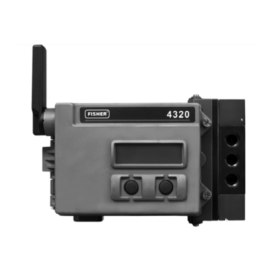
On/Off Control Option Contents Figure 1. Fisher 4320 Wireless Position Monitor Introduction ....... . . -
Page 3: Introduction
To avoid personal injury or property damage, it is important to carefully read, understand, and follow all of the contents of this manual, including all safety cautions and warnings. If you have any questions about these instructions, contact your Emerson Process Management sales office before proceeding. - Page 4 Instruction Manual 4320 Position Monitor D103621X012 October 2012 Figure 2. Control Operation—Wireless Automated Valve CHANGE COMMAND CHANGE COMMAND RESULTS IN VALVE CHANGE CONTROL SYSTEM HOST WIRELESS NETWORK GATEWAY VALVE POSITION FEEDBACK COMMAND TO MAKE A VALVE CHANGE STARTS AT THE CONTROL SYSTEM HOST AND IS SENT TO THE GATEWAY. ‚...
-
Page 5: Terminology
Educational Services For information on available courses for the 4320 wireless position monitor, as well as a variety of other products, contact: Emerson Process Management Educational Services, Registration P.O. Box 190; 301 S. 1st Ave. Marshalltown, IA 50158-2823... - Page 6 Instruction Manual 4320 Position Monitor D103621X012 October 2012 Table 1. Specifications Available Mountings not to exceed 1 ppm weight (w/w) or volume (v/v) basis. Condensation in the air supply should be Quarter‐turn rotary‐shaft minimized. sliding‐stem or Gas: Natural gas must be clean, dry, oil-free and linear applications noncorrosive.
- Page 7 Instruction Manual 4320 Position Monitor October 2012 D103621X012 Table 1. Specifications (continued) Electromagnetic Compatibility Electrical Classification Meets EN 61326‐1 (First Edition) CSA (C/US)— Intrinsically Safe Immunity—Industrial locations per Table 2 of ATEX— Intrinsically Safe the EN 61326‐1 standard. Performance is IECEx—...
- Page 8 3. Due to the combustible nature of the lithium content, the power module has special installation, operation, storage, and/or shipping requirements. Observe all warnings included with the power module before installing, operating, storing, or shipping. Contact your Emerson Process Management sales office if additional information is needed.
-
Page 9: Installation
Instruction Manual 4320 Position Monitor October 2012 D103621X012 Table 4. Device Variables DEVICE VARIABLE INDEX DESCRIPTION Published To Gateway Position PERCENT_OF_SPAN Travel (% of Calibration Output Span) Closed/Low Limit Switch CLOSED_TRIGGER Reports Closed/Low condition (1 = Tripped, 0 = Not Tripped) Opened/High Limit Switch OPEN_TRIGGER Reports Opened/High condition... -
Page 10: Installing Standard And Extended Life Power Module
Instruction Manual 4320 Position Monitor D103621X012 October 2012 WARNING The 4320 power module contains two primary lithiumthionyl chloride batteries. Under normal conditions of use, the battery materials are selfcontained and are not reactive as long as the batteries and power module integrity are maintained. - Page 11 4. If you are replacing the power module see the additional steps to reset the power module remaining life counter, in the Resetting Power Module Variables procedure found on page 59. 5. Close the cover and tighten the instrument cover screws. Figure 5. Fisher 4320 Wireless Position Monitor with Battery Sourced Power Modules BANANA PLUG CONNECTORS (4) PWR TERMINAL...
-
Page 12: Network Setup
Instruction Manual 4320 Position Monitor D103621X012 October 2012 Network Setup The 4320 should have wireless network parameters configured prior to becoming part of a wireless network. All WirelessHART devices within a network have two network parameters that are the same; the Network ID and the Join Key. -
Page 13: Using Ams Wireless Configurator Or Ams Device Manager
Instruction Manual 4320 Position Monitor October 2012 D103621X012 Using AMS Wireless Configurator or AMS Device Manager (Using a HART Modem) 1. Verify that AMS has a device description (DD) loaded for the 4320 Device Revision 3 (DD Revision 1 or later). Note 4320 DD's for AMS are available for download at: http://www2.emersonprocess.com/en-US/documentation/deviceinstallkits/Pages/deviceinstallkitsearch.aspx... -
Page 14: Hazardous Area Classifications And Special Instructions For "Safe Use" And Installations In Hazardous Locations
Special instructions are listed by approval. Note This information supplements the nameplate markings affixed to the product. Always refer to the nameplate itself to identify the appropriate certification. Contact your Emerson Process Management sales office for approval/certification information not listed here. WARNING Failure to follow these conditions of “safe use”... - Page 15 Instruction Manual 4320 Position Monitor October 2012 D103621X012 ATEX Intrinsically Safe II 1 G Battery Sourced Power Module Ex ia IIC T3/T4/T5 Ga Enclosure: Type 4X and IP66 Special Conditions of Use The apparatus must be only connected to certified intrinsic safety equipment and this combination must be compatible regarding intrinsic safety rules.
- Page 16 Instruction Manual 4320 Position Monitor D103621X012 October 2012 Figure 7. Loop Schematic Notes; See Figure 8 for Battery Module Assembly INSTALLATION MUST BE IN ACCORDANCE WITH THE NATIONAL WIRING PRACTICES OF THE COUNTRY IN USE. BARRIERS MUST BE CONNECTED PER MANUFACTURE'S INSTALLATION INSTRUCTIONS. INTRINSICALLY SAFE APPARATUS MAY BE CONNECTED TO ASSOCIATED APPARATUS NOT SPECIFICALLY EXAMINED IN SUCH COMBINATION.
-
Page 17: Valve / Actuator Mounting
Instruction Manual 4320 Position Monitor October 2012 D103621X012 Valve / Actuator Mounting If ordered as a part of a control valve assembly, the factory will mount the wireless position monitor on the actuator and calibrate the instrument. If you purchased the wireless position monitor separately, you will need a mounting kit to mount the wireless position monitor on the actuator. - Page 18 Instruction Manual 4320 Position Monitor D103621X012 October 2012 Figure 9. Travel Range VALID TRAVEL RANGE 25 mm (1 INCH) SHOWN MAGNET ASSEMBLY (ATTACHED TO VALVE STEM) X0543 There are a variety of mounting brackets and kits that are used to mount the 4320 to different actuators. However, despite subtle differences in fasteners, brackets, and connecting linkages, the procedures for mounting can be categorized as follows: D Linear or sliding‐stem actuators with up to 210 mm (8.25 inch) travel...
-
Page 19: Sliding-Stem (Linear) Actuators (E.g. Fisher 667)
Instruction Manual 4320 Position Monitor October 2012 D103621X012 Sliding‐Stem (Linear) Actuators (e.g. Fisher 667) Before mounting, verify that linear travel is greater than one‐half and not more than the maximum recommended travel of the feedback kit. 1. Attach the mounting bracket to the actuator. 2. -
Page 20: Guidelines For Mounting On Quarter-Turn (Rotary-Shaft) Actuators
Instruction Manual 4320 Position Monitor D103621X012 October 2012 Figure 12. Housing and Mounting for Linear and Figure 13. For Rotary‐Shaft Actuators (Typical Quarter‐Turn Actuators Mounting Bracket) OPTIONAL MOUNTING HOLES ROTARY MOUNTING ON/OFF BRACKET CONTROL OPTION MOUNTING HOLES FOR ON/OFF CONTROL OPTION ROTARY NAMUR, M6 NOTE: ANY OF THE MOUNTING HOLES MAY BE USED FOR LINEAR ACTUATORS... - Page 21 Instruction Manual 4320 Position Monitor October 2012 D103621X012 Figure 14. Mounting—Rotary Magnet Assembly MOUNTING FACES MAGNET MOUNTING FACES ASSEMBLY 19.5 $ 0.8 (0.77 $ 0.03) ON/OFF CONTROL OPTION BASE OF HOUSING (INCH) GE59831 Figure 15. Magnet Assembly Orientation ORIENTATION AT ONE TRAVEL EXTREME MOUNTING BRACKET ORIENTATION...
-
Page 22: Pneumatic Hookup Procedure For On/Off Control Option
While use and regular maintenance of a filter that removes particles larger than 40 micrometers in diameter will suffice in most applications, check with an Emerson Process Management field office and industry instrument air quality standards for use with corrosive gas or if you are unsure about the proper amount or method of air filtration or filter maintenance. - Page 23 Instruction Manual 4320 Position Monitor October 2012 D103621X012 Figure 16. 4-Way Spool Valve Installation SUPPLY EXHAUST OF PORT 4 EXHAUST OF PORT 2 (WHEN ACTUATOR OPENS) (WHEN ACTUATOR CLOSED) 5 1 3 FAIL LAST POSITION PORT TO PORT TO ACTUATOR OPEN ACTUATOR CLOSE ALWAYS INSTALL ALWAYS INSTALL...
-
Page 24: Communication Connections
Instruction Manual 4320 Position Monitor D103621X012 October 2012 Communication Connections A HART communicating device, such as a 475 or 375 Field Communicator, interfaces with the 4320 wireless position monitor. Convenient termination points are located inside the front cover, as shown in figure 5. The polarity-insensitive connection pins provide access to the Maintenance Port defined in the WirelessHART specifications. - Page 25 Faster than publish rate sampling can only be configured when at least one of the three burst messages is being triggered. Refer to Advanced Wireless Reporting (Report By Exception and Delayed Trigger Reporting) on page 34 for additional information on faster sampling. Consult the Emerson Smart Wireless Gateway information for details on network size, available at http://www2.emersonprocess.com/en-US/brands/rosemount/Wireless/Wireless-Gateway/Pages/index.aspx...
-
Page 26: Basic Setup
The two buttons on the LCD display (see figure 21) are used to activate the display when the LCD is in the sleep state (blank or off). The buttons can be pressed alone or simultaneously. The Emerson logo will display when the LCD is activated from a HART “squawk”... -
Page 27: Quick Position
Instruction Manual 4320 Position Monitor October 2012 D103621X012 Figure 21. Local Interface Flow Chart SLEEP QUICK POSITION STATUS LOGO LANGUAGE left right squawk both right left right Output Calibrate Calibrate Power Network right left left left Mode right left Voltage Toggle Valve Network ID right... -
Page 28: Power
Instruction Manual 4320 Position Monitor D103621X012 October 2012 Power The power status menu is entered from the STATUS menu by pressing SELECT. Press SELECT to see the voltage of the power module. Press NEXT to display the estimated remaining life of the power module. Note The remaining life value of the power module is an estimate. -
Page 29: Calibration
Instruction Manual 4320 Position Monitor October 2012 D103621X012 Calibrate To access the Calibration menu with on/off control press the right button to access the STATUS menu, then the left button (NEXT), then the right button (SELECT). Press the right button from the STATUS menu to access the Calibration menu when using the monitoring option. - Page 30 Instruction Manual 4320 Position Monitor D103621X012 October 2012 Note During the manual calibration procedure, the valve is moved to one position and MARKED. The valve is then moved to other end of travel or rotation and the second position is recorded (MARKED). Earlier calibration points can be used or discarded. Applying calibration points without changing the valve position will result in the calibration attempt being unused or discarded.
-
Page 31: Using The Field Communicator
Instruction Manual 4320 Position Monitor October 2012 D103621X012 Output (On/Off Control) Access the Output menu by pressing the right button to access the STATUS menu, the left button (NEXT), and then NEXT again. In the OUTPUT menu you can view/change the device mode. Press SELECT to view the current device mode. Press the left button to toggle the mode from OUT OF SERVICE to IN SERVICE or vice versa. - Page 32 Instruction Manual 4320 Position Monitor D103621X012 October 2012 Device Status shows device status. If the status is other than Good, the menu item may be expanded to display a list of active alerts, together with their PlantWeb Alert categories, description, recommended actions, and (where applicable) helpful troubleshooting procedures, images, or variable values.
-
Page 33: Configure
Instruction Manual 4320 Position Monitor October 2012 D103621X012 Device Information Identification—includes general device and functional assignment information, including instrument manufacturer, device tags, model, unique ID, description, message, polling address, serial numbers, commissioning date, and device capabilities, which includes technical information about the device. Revisions—includes device revision information, including Universal, Device, Firmware, Hardware, and DD. - Page 34 Instruction Manual 4320 Position Monitor D103621X012 October 2012 Figure 23. Field Communicator Menu Tree—Configure 2‐1 Guided Setup 1 Device Setup 2 Configure Alerts 3 Join Device to Network Configure 4 Configure Publishing Online 1 Guided Setup 1 Overview 2 Configure 2 Manual Setup 2‐2‐1 2‐2‐2-1 Wireless 3 Alert Setup (see below) 3 Service Tools Identification 4 Calibration (see below)
- Page 35 Instruction Manual 4320 Position Monitor October 2012 D103621X012 D Wireless Transmit Power—indicates the radiated power setting of the radio. Change Power—select the radiated power setting of the radio: High or Low. Wireless Mode—displays the current communication state of the device, or its ability to provide information to the network.
- Page 36 Instruction Manual 4320 Position Monitor D103621X012 October 2012 Report By Exception (RBX) or Triggered Burst Mode allow you transmit data only when a change occurs. When a triggered burst mode is enabled, a “trigger” variable is identified, and the data is sampled and published at a fast rate when there is a significant change in the monitored trigger variable.
- Page 37 Instruction Manual 4320 Position Monitor October 2012 D103621X012 Description—enter a descriptor for the application with up to 16 characters. The descriptor provides a longer user‐defined electronic label to assist with more specific instrument identification than is available with the HART tag. Message—enter any message with up to 32 characters.
- Page 38 Instruction Manual 4320 Position Monitor D103621X012 October 2012 Configure Structure—select whether the control mode is snap-acting, whether the switch state will latch when tripped, and whether the position variable is labeled for valve or process reporting. Reporting Precision Accuracy of the device is 1% of the nominal span, however you may select an additional decimal place for reporting. D Burst Message 0 Message 1...
- Page 39 D103621X012 If an Emerson Gateway is in use, the 'Emerson-Specific' choice can be used. It combines the 4 Dynamic Variables and the Additional Status in one message. However, it does not include the Loop Current or PV %Range variables. If the control system requires PV %Range and Loop Current, make sure that these two variables are included in a message configured for 'Selected Device Variables'.
- Page 40 Instruction Manual 4320 Position Monitor D103621X012 October 2012 D Fault Behavior (On/Off Control) The device can be configured to enter a Fault State that attempts to drive the pneumatic output to the configured “fault state”. Note When a fault condition is enabled and is activate (i.e., in the fault state), the device does not act on the set point from the host. The device controls the valve using the set point defined during configuration.
- Page 41 Allows you to edit or view Power Module Type, Voltage, Power Module Date, Battery Life, and Reset Module Data. Note Contact your Emerson Process Management sales office if a replacement power module is required. Do not re‐use power modules from other units.
- Page 42 Instruction Manual 4320 Position Monitor D103621X012 October 2012 Reset Accumulated Count —select Yes to reset the accumulated count to 0 (zero). This is typically done when maintenance to valve and/or actuator has been performed. Select No to retain the current cycle count. Enable Cycle Count Alert Cycle Trip Point—used to adjust the trip point.
- Page 43 Instruction Manual 4320 Position Monitor October 2012 D103621X012 D Controller Alerts (On/Off Control) Note Controller Alerts are disabled by default. Mode Alerts Device Not in Service—indicates the Set Point is not being applied to the process. Output Fault State—indicates that the control output has been driven to the configured fault state. Enable 'Out of Service' Enable 'Fault State' Alert Tracking Alerts...
- Page 44 Instruction Manual 4320 Position Monitor D103621X012 October 2012 Open Time Alerts Note Open Time Alerts are not available in snap-acting mode. Open Stroke Time Alert—indicates that the last open stroke time fell outside the time limits allowed by the configuration. Open Stroke (Cal)—indicates the time required to complete open stroke during Auto Calibration.
-
Page 45: Service Tools
Instruction Manual 4320 Position Monitor October 2012 D103621X012 Output Assignment—allows you to associate the output ports with with a stroke direction (open or close) by observing the action during a stroke. This procedure is used to complete a controller calibration process if Manual Calibration was used for the sensor, and is the only way to assign output sense in snap-acting mode. - Page 46 Instruction Manual 4320 Position Monitor D103621X012 October 2012 Figure 24. Field Communicator Menu Tree—Service Tools 3‐2-1 Variable Summary 1 Process 2 Dwell 3‐2 Variables 3 Valve 4 Device 1 Variable Summary 5 Run Time Extremes Field Communicator 2 Valve Position 3 Last Close Stroke Service Tools 1 Offline 3‐2-1-5 4 Last Open Stroke Run Time Extremes 2 Online...
- Page 47 Instruction Manual 4320 Position Monitor October 2012 D103621X012 Valve (On/Off Control) Note Valve variables are only available when not in snap-acting mode. Last Close Stroke—the time needed to complete the most recent stroke from opened to closed. Last Open Stroke—the time needed to complete the most recent stroke from closed to opened. Quality variables below Last Close Stroke and Last Open Stroke indicate the overall process data quality of the item.
- Page 48 Instruction Manual 4320 Position Monitor D103621X012 October 2012 Communications Contains Network and Burst information. Follow the Field Communicator prompts access Network, Review Burst Message, Hardware Triggering, and Review Event Configuration. Network Wireless Mode—indicates the current mode; Idle, Disconnected, Searching, Connected, or Operational Join Mode—gives instructions to the device with regard to joining the WirelessHART network.
- Page 49 Follow the Field Communicator prompts to access Locate Device, Calibration, Controller, Power Module, Reset/Restore. D Locate Device —select Locate Device to command the device to display the Emerson logo to assist a technician in locating it. Specify the number of repeats at approximate 5 minutes each.
- Page 50 Instruction Manual 4320 Position Monitor D103621X012 October 2012 Output Assignment—allows you to associate the output ports with with a stroke direction (open or close) by observing the action during a stroke. This procedure is used to complete a controller calibration process if Manual Calibration was used for the sensor, and is the only way to assign output sense in snap-acting mode.
-
Page 51: Accessing Features
Instruction Manual 4320 Position Monitor October 2012 D103621X012 Reset Module Data D Reset/Restore Reset Device is the equivalent of a power cycle, and will cause the device to drop off the wireless network, affecting communications for any neighbor devices that are passing packets through it. Only recommended when instructed by service personnel. -
Page 52: Diagnostics
Instruction Manual 4320 Position Monitor D103621X012 October 2012 AMS Wireless Configurator or AMS Device Manager Go to Configure, Manual Setup, then select Change Limit Switch Parameters from the Limit Switch tab to make changes to the trip point settings. See figure 26. Figure 25. - Page 53 For information on using Modbus or OPC with the 4320 wireless monitor refer to 4310/4320 Wireless Position Monitor OPC System Integration Guide (D103530X012) or 4310/4320 Wireless Position Monitor Modbus System Integration Guide (D103529X012), available from your Emerson Process Management sales office or at www.Fisher.com.
- Page 54 Instruction Manual 4320 Position Monitor D103621X012 October 2012 Go to Service Tools, Variables, then select the Valve tab to view Last Close Stroke Time or Last Open Stroke Time and the Dwell Time in the current state, as shown in figure 29. Go to Service Tools, Variables, select the Dwell tab and Read Device Variables to view opened/high or closed/low dwell and transition dwell times, as shown in figure 30.
- Page 55 Instruction Manual 4320 Position Monitor October 2012 D103621X012 Go to Service Tools, Variables, then select the Run Time Extremes tab to view the temperature extremes, as shown in figure 32. Go to Service Tools, Maintenance, then select the Controller tab to view the Active Fault Conditions, as shown in figure 33.
-
Page 56: Locate
Select Online, Service Tools, Maintenance, then Locate Device from the Locate tab to access Locate, as shown in figure 34. Locate Device displays the Emerson Logo steadily for 5 minutes on the local display of the device. You may select how many time the squawk is repeated at 5 minutes per request. -
Page 57: Maintenance
Instruction Manual 4320 Position Monitor October 2012 D103621X012 Maintenance When replacing any of the components of the 4320 wireless position monitor the maintenance should be performed in an instrument shop whenever possible. WARNING Always wear protective clothing, gloves, and eyewear when performing any maintenance procedures to avoid personal injury or property damage. -
Page 58: Replacing The Instrument
30_C (86_F). Note The batteries contained in the field replaceable power module are not rechargeable. Contact your Emerson Process Management sales office if a replacement power module is required. -
Page 59: Removal
Instruction Manual 4320 Position Monitor October 2012 D103621X012 Note Proper disposal of used power modules, which contain two lithiumthionyl chloride (LiSOCl ) batteries, is required. Disposal should be done in accordance with applicable local rules and regulations. For additional information refer to the manufactures guidelines for disposal of lithium batteries: http://www.tadiranbat.com/pdf.php?id=0111_-_Guidelines_for_Disposal_of_Lithium_Cells_and_Batteries (available at www.tadiranbat.com). -
Page 60: Resetting Power Module Variables
Instruction Manual 4320 Position Monitor D103621X012 October 2012 Figure 35. Hot Swap ATTACH CLIPS TO POWER AUXILIARY PORTS ATTACH BANANA PLUG CONNECTORS TO NEW POWER TEST LEADS WITH BANANA PLUG MODULE ASSEMBLY CONNECTORS AND MICRO-PLUNGER CLIPS X0558 Resetting Power Module Variables When power modules are replaced, you must reset Battery Life Remaining (shown in figure 36), which can be used for scheduling maintenance of the power module. - Page 61 Instruction Manual 4320 Position Monitor October 2012 D103621X012 AMS Wireless Configurator or AMS Device Manager In AMS Device Manager select Configure, Manual Setup, then select Reset Power Module Variables from the Power tab, as shown in figure 36, to reset the power module variables. 1.
-
Page 62: Component Maintenance-On/Off Control Option
This section describes removing and replacing the spool valve and pneumatic gasket, the pneumatic interface and housing gasket, and the filter assembly. Key numbers are shown in figure 37 unless otherwise indicated. Figure 37. Fisher 4320 Assembly ON/OFF CONTROL OPTION NOTE:... -
Page 63: Spool Valve And Pneumatic Gasket Removal
Instruction Manual 4320 Position Monitor October 2012 D103621X012 Spool Valve and Pneumatic Gasket Removal 1. Remove the four hex socket cap screws (key 18). 2. Carefully remove the spool valve (key 17). If needed, gentle prying can be used at the corners to assist in separating the spool valve from the 4320. -
Page 64: Pneumatic Interface And Gasket Installation
Use only genuine Emerson replacement parts. Components that are not supplied by Emerson Process Management should not, under any circumstances, be used in any Fisher instrument. Use of components not supplied by Emerson Process Management may void your warranty, might adversely affect the performance of the instrument and could cause personal injury or property damage. -
Page 65: Replaceable Parts
Fisher is a mark owned by one of the companies in the Emerson Process Management business unit of Emerson Electric Co. Emerson Process Management, Emerson, and the Emerson logo are trademarks and service marks of Emerson Electric Co. All other marks are the property of their respective owners. HART and WirelessHART are marks owned by the HART Communication Foundation. - Page 66 46 - Opened 48 - Error 1. Supplement to TopWorx™ 4310 Wireless Position Monitor, with On/Off Control Option Instruction Manual (D103622X012) Fisherr 4320 Wireless Position Monitor, with On/Off Control Option Instruction Manual (D103621X012) Available from your Emerson Process Sales office, or www.emersonprocess.com...
- Page 67 Responsibility for proper selection, use, and maintenance of any product remains solely with the purchaser and end user. Fisher and TopWorx are marks owned by one of the companies in the Emerson Process Management business unit of Emerson Electric Co. Emerson Process Management, Emerson, and the Emerson logo are trademarks and service marks of Emerson Electric Co.
Need help?
Do you have a question about the Fisher 4320 and is the answer not in the manual?
Questions and answers