Headwall Nano-Hyperspec Operation Manual
Airborne package
Hide thumbs
Also See for Nano-Hyperspec:
- Installation and operation manual (52 pages) ,
- Operation manual (64 pages)
Table of Contents
Advertisement
Advertisement
Table of Contents

Subscribe to Our Youtube Channel
Related Manuals for Headwall Nano-Hyperspec

Summary of Contents for Headwall Nano-Hyperspec
- Page 1 AIRBORNE OPERATIONS YPERSPEC ® IRBORNE ACKAGE Operations Manual...
- Page 2 Headwall Photonics, Inc. is strictly prohibited. All information provided in this manual is believed to be accurate and reliable. No responsibility is assumed by Headwall Photonics, Inc. for its use. Headwall Photonics, Inc. reserves the right to make changes to this information without notice.
-
Page 3: Document Revision Tracking
CHANGE TRACKING DOCUMENT REVISION TRACKING Table 1-1. Document Revisions Date Name Page Detail 6/2016 Chenevert Added note about closing the live video and waterfall views to prevent GPS data drop. Added steps for remote trigger using GPIO functionality. 7/5/2016 Chenevert 1-14,15 Added detail about IMU connections. - Page 4 CHANGE TRACKING...
-
Page 5: Table Of Contents
AIRBORNE OPERATIONS Table of Contents Document Revision Tracking ................. a Airborne Package Operation ................. 3 ® Nano-Hyperspec — Airborne Package Components ........3 Individual Components ..................4 ® Nano-Hyperspec ......................... 4 IMU ............................5 GPS Antenna......................... 6 IMU Connection and Orientation.................7 Component Interconnection .................7... - Page 6 AIRBORNE OPERATIONS Headwall Polygon Tool ..................40 Polygon Tool Functions......................42 Multiple Polygons......................... 44 Adding Polygons to the GPS Polygon Editor..............45 GPS Triggers ......................47 GPS Remote Triggers ...................50 Pre-flight, Way point Planning ................51...
-
Page 7: Airborne Package Operation
III, onto the computer that contains ® ® Hyperspec III and SpectralView ® ® The operation of the Nano-Hyperspec unit is covered in the manual for that device. The Nano-Hyperspec is identified within the individual components section of Airborne Operations for ease of instruction. -
Page 8: Individual Components
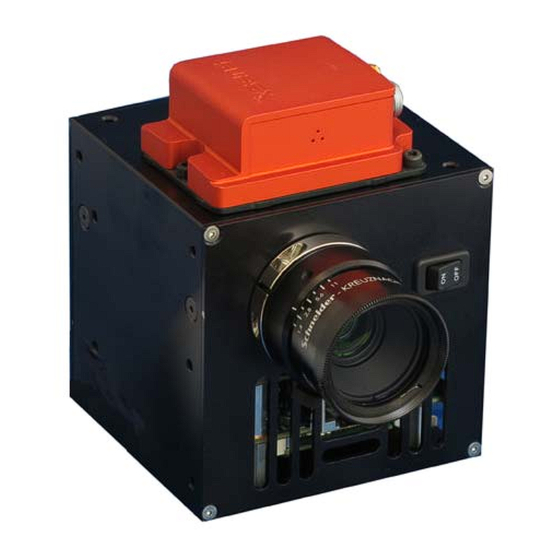
AIRBORNE PACKAGE ® Figure 1-1. Nano-Hyperspec — Airborne Package. 1.2 INDIVIDUAL COMPONENTS ® 1.2.1 Nano-Hyperspec ® Figure 1-2. Nano-Hyperspec , with Lens. -
Page 9: Imu
The positional data from the unit is then used for ortho-rectification of the scan data ® within the SpectralView application. The Headwall supplied cable used to connect the IMU to the Nano is the minimal length to eliminate an interference. Figure 1-3. IMU The software to operate the IMU and generate positional data is embedded within the device. -
Page 10: Gps Antenna
1.2.3 GPS Antenna. ® The GPS antenna is used to define the initial location of the Nano-Hyperspec unit once the IMU has been installed. During the flight the GPS antenna captures the location of the system and sends that data to the IMU and Nano for inclusion into the data. -
Page 11: Imu Connection And Orientation
Hyperspec III. Set the parameters for the flight, leave the Nano powered ON and disconnect the Cat ® 6 cable. Once the scan is complete, the data from the Nano-Hyperspec needs to be downloaded to the operating ®... -
Page 12: Power Connection
AIRBORNE PACKAGE 1.4.2 Power Connection. ® The Nano-Hyperspec uses 9.5 to 25 VDC power. Connect the positive and negative leads to an appropriate power source. Insert the power connector into the Nano Power Connector location, identified the following figure. Figure 1-6. Nano Power Location. -
Page 13: Nano-Imu Attachment
For aerial data collection the user attaches the IMU to a Headwall sensor and mounts the pair onto a viewing platform. When ordered, the IMU can be installed and configured at the Headwall facility prior to shipping. When the Nano is prepared for use, the IMU can be attached to only one of the four sides of the Nano that match the mounting holes of the IMU. - Page 14 Figure 1-8. Four IMU Orientations. Notice in the above figure that from left to right the word HEADWALL rotates from the twelve-o-clock position through to the nine-o-clock position. Additionally, the orientation of the IMU to the front/back axis of the Nano varies. These positional variations are what need to be accounted for in the Ortho-rectification step of the data cube analysis.
-
Page 15: Imu Data/Power Connection
Orient the Nano, with the IMU attached, so the Nano serial number label and cooling fan are facing forward, as in the following figure. The IMU data port is the white connector, as shown. ® Figure 1-11. Nano-Hyperspec Data Port View. 1-11... - Page 16 AIRBORNE PACKAGE b. Remove the LEMO-Data cable from the airborne package. Figure 1-12. LEMO-Data Cable. c. Hold the data serial connector and orient it so the holes in the cable-end connector match the pins in the Nano data port connector. d.
- Page 17 AIRBORNE PACKAGE Figure 1-14. Align Red Dots, LEMO and IMU. CAUTION Do not twist the LEMO connector into the IMU connector. This will damage the pins and make the cable useless. The LEMO is a push-pull connector. f. Hold the Nano in place and gently press the two connector pieces together until the connectors appear as below, Figure 1-15.
-
Page 18: Imu, Gps Connection
AIRBORNE PACKAGE 1.4.5 IMU, GPS Connection. a. Remove the GPS Antenna from the package. Figure 1-16. GPS Antenna. b. Take the motion tracker connector and align it with the gold connector on the IMU. Figure 1-17. GPS to IMU Connection. c. - Page 19 AIRBORNE PACKAGE ® references prior to operation. Follow the steps in the Hyperspec III manual for this procedure. The second possible error may be the connection between the Nano and the GPS. If a GpsMonitor Command error occurs it indicates the Nano is not recognizing the IMU.
-
Page 20: Flight Planning
GPS triggering can be set using the Headwall Polygon tool. Headwall recommends using the polygon tool, http://www.headwallphotonics.com/polygon- tool, as a means of identifying the scan area and setting the GPS start and stop triggers for the Nano. This, coupled with preprogrammed, automatic flight, eliminates the operator variable in the scanning process, and generally leads to better results. - Page 21 AIRBORNE PACKAGE Close the Live Video. Click the Settings button, opening the Settings screen. Click the Sensor tab, shown in the following figure. Figure 1-20. Settings, Sensor Tab. The operational details for the numbered sections are in the following table. Verify the settings conform to the system configuration.
-
Page 22: Capture Function
Defines reading of rising or falling edge or both For most applications, using the Xsens IMU from Headwall, users can perform the manual triggering with the GPIO ID set for the IMU and the GPIO External Trigger selected. The External Trigger is used to toggle captures when check box selected. -
Page 23: Gps/Imu Mapping
GPS/IMU MAPPING CHAPTER 2 GPS/IMU MAPPING 2.1 OVERVIEW Depending on where the Airborne unit is deployed, the GPS/IMU device needs to have the internal magnetic field sensors calibrated. This should be done on a regular schedule, if the unit is repeatedly used in a particular location, or if the device is used in multiple locations separated by a significant distance, the device should be calibrated prior to field use. - Page 24 GPS/IMU MAPPING Figure 2-2. Installer Options Screen. (5) Check the boxes relevant to the desired download. In this example the two next to the MT Manager and Magnetic Field Mapper (MFM) will be selected. The MT Manager requires a license activation number, the Magnetic Field Mapper does not.
- Page 25 GPS/IMU MAPPING Figure 2-4. MT Manager Start Window. (8) Click, Next. Figure 2-5. MT Manager License Window. (9) Enter the license key from the document set aside earlier and click, Next. 2-21...
- Page 26 GPS/IMU MAPPING Figure 2-6. MT Manager Install Location. (10) When the location screen opens, accept the default or browse to and accept another location. Then click, Next. (11) The Ready to Install Screen opens, click Install. (12) The installation Progress Screen opens. Allow the installation to finish. Figure 2-7.
- Page 27 GPS/IMU MAPPING Figure 2-8. Magnetic Field Mapper Installation Window. (14) Click Next. (15) Select the Accept option in the End User License Agreement window and click, Next. Figure 2-9. Installation Location Window. (16) Accept the default installation location, or browse to another location. After accepting the installation location, click Next.
- Page 28 GPS/IMU MAPPING Figure 2-10. Ready to Install Window. (17) When the Magnetic Field Mapper window, in the above figure opens, click Install. (18) The Progress window opens. Allow the installation to complete, as shown in the following figure. Figure 2-11. Magnetic Field Mapper Installation Complete. (19) Click Finish.
-
Page 29: Magnetic Mapping Process
GPS/IMU MAPPING 2.3 MAGNETIC MAPPING PROCESS NOTE To perform the Magnetic Mapping the GPS/IMU device must be mounted to the sensor, with the GPS/IMU oriented as it will be used during the scanning process. Refer to Airborne Package Operation chapter for the proper installation and interconnection procedures. -
Page 30: Magnetic Mapping Procedure
GPS/IMU MAPPING Figure 2-13. Secured LEMO-GPS/IMU Connectors. (5) Once the two halves pressed together, turn the locking wheel clockwise until it stops. This secures the LEMO connector into place. CAUTION The cable should be kept at a distance from the sensor/GPS/IMU unit. A close proximity may distort the results. - Page 31 GPS/IMU MAPPING (a) If the computer doesn’t find the GPS/IMU an error will show. (b) Close the error message and wait a minute, then click Scan again. Figure 2-15. Magnetic Field Mapper Input Type. (4) Select the input type, the Use Motion Tracker is selected. (5) Click Next.
-
Page 32: Calibration Method
GPS/IMU MAPPING 2.3.3 Calibration Method. During a 3D calibration measurement, the object to which the sensor is attached has to be rotated through as many different orientations as possible, it may help to think about ‘scanning’ the surface of a sphere with the GPS/IMU x-axis. It is important to cover as many orientations as possible, at least as many to cover the application’s envelope of motion. - Page 33 GPS/IMU MAPPING (3) Check the optional warnings and review the quality indicators. (4) Review the mapping results with the following steps. Figure 2-19. Magnetic Mapping Results. (5) To view the calibration results, click Show Results. (6) The following window opens, graphically presenting the calibration results. The results are contained within three generated files: Mapper Results, showing the sphere layout and travel path on a sphere, Normal plotted chart and Residual histogram.
-
Page 34: Examples Of Scanning Errors
GPS/IMU MAPPING 2.3.4 Examples of Scanning Errors. The following figures show the results of various poor scans. The cause of each error is written in the figure title. The location that best identifies the error in the presented scan data is identified with red arrows for clarity. Figure 2-21. - Page 35 GPS/IMU MAPPING Note the lower left image where the trace indicators are random lengths and shifted to the front of the sphere. The empty histogram has no distribution, which is the opposite of the acceptable scan figure. Figure 2-23. Erroneous Scan, Points too Concentrated. The results shown in the above figure are from limited rotation of the sensor/IMU device.
-
Page 36: Ortho-Rectification: Configure Imu
GPS/IMU MAPPING Figure 2-24. Not Enough Data Points The above figure shows the results for insufficient test data points. The top left of the figure shows a limited path that was generated in the motion. The lower left portion shows the small number of data points from this limited path. The top right of the figure shows the empty distribution and data fully shifted to the right of the median of the graph. - Page 37 GPS/IMU MAPPING Figure 2-24. MT Manager, Main Screen. (2) Click the Settings icon, indicated in the figure above. The Settings panel opens, as in the following figure. Figure 2-25. MT Settings Panel. (3) In the RotSensor grid, within the red rectangle above, enter the following data: 2-33...
- Page 38 GPS/IMU MAPPING Table 2-1. RotSensor Values 6.12574E-17 6.12574E-17 (1) After the values are entered, the Write to MT button will become active. (2) Click on the Write to MT button, circled in the upper right. The values entered may be rounded after clicking the button.
-
Page 39: Airborne Operations, Pre-Flight Procedures
Chapter 3 Airborne Operations, Pre-Flight Procedures The following section identifies and details the use of the Headwall Polygon tool to define the flight path and scan coverage of a UAS mounted sensor. In addition to defining the scan area and path, operators should, as part of the pre- flight plan, identify the speed altitude and therefore, focus of the sensor prior to the actual flight. - Page 40 GPS/IMU Figure 3-2. FOV Calculator. (5) As shown above, the user identifies the distance, the altitude of the sensor, to the scanned object. The user also identifies the linear values and the scan distance values. Last, enter the speed of the sensor, the flight speed. (6) The FOV calculator output is the FPS value.
-
Page 41: Gps Configuration And Polygons
GPS/IMU 3. 2 GPS CONFIGURATION AND POLYGONS (1) Power ON the operating computer, if necessary, and connect it to the Internet. ® (2) Open Hyperspec III, if necessary, and click the GPS button. ® Figure 3-1. Hyperspec III with GPS. (3) On the GPS control, click Capture Polygons button. - Page 42 This tool is NOT suitable for piloting a UAV or otherwise defining a flight plan. Control of any UAV always remains the sole responsibility of the operator. Headwall provides this tool as a convenient means of configuring the hyperspectral sensor to capture data at specific points of interest.
-
Page 43: Capture Polygons
GPS/IMU 3. 3 CAPTURE POLYGONS The Capture Polygons function allows a user to select latitude and longitude points to create a specific area to be scanned. Scanning can be started either manually or automatically when the system enters the area defined by the polygon and likewise stop when the system leaves the polygon. -
Page 44: Headwall Polygon Tool
3. 4 HEADWALL POLYGON TOOL If the coordinates for the polygon or polygons are not immediately available, they can be generated with the Headwall Polygon Tool.Connect the computer to a network with an Internet connection. Click, or copy and paste the following URL: http://www.headwallphotonics.com/polygon-tool. - Page 45 GPS/IMU Scroll down the page to see a map in the lower half. The map has multiple functions, controlled by either buttons, clicking the cursor or directly entering data. For example, users can set the latitude and longitude of the general area they wish to start scanning by entering the coordinates in the fields at the top of the map and clicking the Go To button.
-
Page 46: Polygon Tool Functions
GPS/IMU Table 3-5. Functional Area Details -- Continued Number Feature Function/Operation Area Shows total area, in meters squared, covered by a polygon developed on the Refresh After a polygon anchor is dragged with the cursor, clicking this button updates Coordinates the coordinates in the Coordinates panel. - Page 47 GPS/IMU Once the view and location are selected, the next step is to create a polygon target scan area. This is done by finding the location of interest and left clicking the cursor onto the spot of the map or satellite view. Each click creates an anchor point, as shown below.
-
Page 48: Multiple Polygons
GPS/IMU 3. 7 Multiple Polygons. Multiple polygons are created to enable scanning of multiple target areas during a single flight, and is done as follows. (1) Open the Polygon Tool, Coordinates Map. (2) Create a single polygon in the desired target area. Notice the GPS coordinates in the Coordinates panel. Figure 3-1. -
Page 49: Adding Polygons To The Gps Polygon Editor
GPS/IMU 3. 8 Adding Polygons to the GPS Polygon Editor. Once the polygon(s) has been defined in the Polygon Tool, use the following steps to add them to the editor. (1) Click the Export button to display all the coordinates. (2) Using the mouse and cursor, select and copy the coordinates from the Coordinates panel in the Polygon Tool ®... - Page 50 GPS/IMU Figure 3-3. Imported Polygon Coordinates. (5) Editing the polygon list is done as follows. (a) Open the Polygon Editor. (b) Click the Select button to select or deselect all polygons. (c) Select an individual polygon name and click Edit to show the GPS coordinates in the Polygon Editor box, as below.
-
Page 51: Gps Triggers
GPS/IMU (6) Click the Apply button. ® (a) The Polygon editor closes and the polygon(s) are loaded in to the GPS window of Hyperspec III. (b) The current location will be shown as a white X on the map. Figure 3-5. GPS with Loaded Polygons. (7) Close the GPS window. - Page 52 GPS/IMU ® Figure 3-1. Hyperspec III Capture Button. (2) The Capture window opens, as shown in the following figure. (3) Click the Enable GPS Triggering check box, circled in red in the following figure. Figure 3-2. Capture Window. (4) Complete the information in the expanded GPS window, seen in the following figure.
- Page 53 GPS/IMU Figure 3-3. Enable GPS Trigger. (5) To use the polygons, set the Roll, Pitch and Yaw values to a Min of -360 and a Max of 360. (6) Select the number of polygons that are active for the scanning process. In the prior example two polygons were loaded.
-
Page 54: Gps Remote Triggers
GPS/IMU Table 3-10. Capture Parameters. Parameter Function Folder Shows the location of the scan data Enable GPS Triggering When selected the image capture is triggered by the polygon method. Active Polygons Shows the number of active polygons. The active polygons will remain active even after restarting the software until they are disabled. -
Page 55: Pre-Flight, Way Point Planning
To obtain useful data cubes during airborne operations the UAS flight path needs to be outside of the defined capture polygon. The minimal distance, from Headwall’s experience, should be 15 meters, preferably 25 meters. The reason is that the sensor needs to be triggered OFF during the UAS maneuvers to change direction. Due to speed and commercial GPS resolution accuracy, the 15-25 meter was empirically developed. - Page 56 To verify that the flight path is adequate, do the following: (1) Open the Headwall Polygon tool. (2) Import the coordinates for the exiting, planned CAPTURE polygon.
Need help?
Do you have a question about the Nano-Hyperspec and is the answer not in the manual?
Questions and answers