Microsemi SmartFusion2 Demo Manual
Soc fpga in-application programming using pcie interface - libero soc v11.8
Hide thumbs
Also See for SmartFusion2:
- User manual (829 pages) ,
- Demo manual (35 pages) ,
- Configuration manual (23 pages)

Related Manuals for Microsemi SmartFusion2


Summary of Contents for Microsemi SmartFusion2
- Page 1 DG0584 Demo Guide SmartFusion2 SoC FPGA In-Application Programming Using PCIe Interface - Libero SoC v11.8...
- Page 2 Within the USA: +1 (800) 713-4113 with the Buyer. Microsemi does not grant, explicitly or implicitly, to any party any patent rights, licenses, or any other IP rights, whether with regard to such information itself or anything described by such information. Information provided in this...
-
Page 3: Table Of Contents
Programming the SmartFusion2 Security Evaluation Kit Board ......8 Connecting the SmartFusion2 Security Evaluation Kit Board to Host PC ..... . . 10 Drivers Installation . - Page 4 Figure 25 Microsemi PCIe Device Found Message in PCIe Demo GUI ......20 Figure 26 IAP Verification Status .
- Page 5 SmartFusion2 Security Evaluation Kit Jumper Settings ........
-
Page 6: Revision History
Revision History Revision History The revision history describes the changes that were implemented in the document. The changes are listed by revision, starting with the most current publication. Revision 5.0 Updated the document for Libero v11.8 software release. Revision 4.0 Updated the document for Libero v11.6 software release (SAR 71564). -
Page 7: In-Application Programming Using Pcie Interface
SmartFusion2 devices. SmartFusion2 devices support IAP using a number of different interfaces. In this demo design, PCIe is used to transfer new programming data. This document describes how to program SmartFusion2 devices through the PCIe interface, and use SmartFusion2 system controller services. -
Page 8: Figure 1 Demo Design Files Top-Level Structure
Serial Controller 0 Host PC (PCIe(x4) GEN 2) SmartFusion2 Step1 Transferring data bitstream from host PC to external Flash through PCIe interface Step2 System controller reads data bitstream from the external flash to program the SmartFusion2 device DG0584 Demo Guide Revision 5.0... -
Page 9: Features
On successful authentication, the Cortex-M3 processor initiates a PROGRAM IAP system controller system service. The system controller fetches the bitstream data from the SPI Flash and programs the flash components of the SmartFusion2 device. IAP can be used to program the FPGA fabric, eNVM, or both FPGA fabric and eNVM. -
Page 10: Running Gui Application On Host Pc
The GUI application is an executable program running on the host PC that transfers the programming file (*.spi) from the host PC to the SmartFusion2 Security Evaluation Kit on-board SPI Flash through the PCI interface. The GUI also allows the user to perform the IAP operations (Authenticate, Program, and Verify) by clicking the corresponding options, as shown in the following figure. -
Page 11: Iap Execution Flow
Browse to the .spi programming file and click WRITE in the GUI. The GUI application running on the host PC starts communicating with the SmartFusion2 device using the PCIe interface. On connecting with the SmartFusion2 device, the GUI sends the programming file size to the Cortex-M3 processor user application and requests to erase the external SPI Flash contents available on the SmartFusion2 Security Evaluation Kit for storing the bitstream data. -
Page 12: Setting Up The Demo Design
The following steps describe how to setup the demo design: Connect the FlashPro4 programmer to the J5 connector of the SmartFusion2 Security Evaluation Kit board. Connect the jumpers on the SmartFusion2 Security Evaluation Kit board as shown in the following table. CAUTION: Switch OFF SW7 while connecting the jumpers. -
Page 13: Programming The Smartfusion2 Security Evaluation Kit Board
In-Application Programming Using PCIe Interface Note: Snapshots of the SmartFusion2 Security Evaluation Kit board with the complete set up is given in the Appendix: SmartFusion2 Security Evaluation Kit Board, page 23. Table 2 • SmartFusion2 Security Evaluation Kit Jumper Settings... -
Page 14: Figure 6 Flashpro4 Programmer Type
In-Application Programming Using PCIe Interface The following figure shows the programmer type as FlashPro4. Figure 6 • FlashPro4 Programmer Type The following steps describe how to configure the device: Click Configure Device. Click Browse and navigate to the location where pcie_iap_top.stp is located and select the file. The default location is: <download_folder>\sf2_iap_using_interface_demo_df\stapl_programming_file Click Open. -
Page 15: Connecting The Smartfusion2 Security Evaluation Kit Board To Host Pc
Board to Host PC The following steps describe how to connect the Security Evaluation Kit board to the host PC: After successful programming, switch OFF the SmartFusion2 Security Evaluation Kit board and shut down the host PC. The following steps describe how to connect the CON1–PCIe Edge Connector either to the host PC or laptop: •... -
Page 16: Figure 9 Device Manager - Pcie Device Detection
Switch on the host PC and check the Device Manager for PCIe Device. The following figure shows the example Device Manager window. If the device is not detected, power cycle the SmartFusion2 Security Evaluation Kit and click option in the Device Manager. -
Page 17: Drivers Installation
In-Application Programming Using PCIe Interface • In the Confirm Device Uninstall dialog box, select Delete the driver software for this device and click OK, as shown in the following figure. After uninstalling previous Jungo drivers, ensure that the PCI device is detected in the Device Manager window. Figure 11 •... -
Page 18: Installing Pcie_Demo Application Gui
2.6.1 Installing PCIe_Demo Application GUI The PCIe_Demo application is a GUI that runs on the host PC to communicate with the SmartFusion2 PCIe endpoint device. It provides PCIe link status, driver information, and demo controls. The PCIe_Demo application invokes the PCIe driver installed on the host PC and provides commands to the driver according to the selection made. -
Page 19: Running The Demo Design
The following steps describe how to run the demo design: Check the host PC Device Manager for the drivers. If the device is not detected, power cycle the SmartFusion2 Security Evaluation Kit board and click scan for hardware changes in Device Manager. Ensure that the board is switched ON. -
Page 20: Iap Step1: Loading Spi Flash With Programming Bitstream
In-Application Programming Using PCIe Interface Click Connect. The application detects and displays the connected Kit, demo design, and PCIe link. The following figure shows the example messages after the connection is established. Figure 18 • PCIe Device Information IAP Step1: Loading SPI Flash with Programming Bitstream The following steps describe how to load the SPI Flash with programming bitstream: Click IAP, as shown in... -
Page 21: Figure 19 Selecting Programming File In Pcie_Demo Application
In-Application Programming Using PCIe Interface Figure 19 • Selecting Programming File in PCIe_Demo Application Click write to move the programming file to the external SPI Flash memory. The SPI Flash memory is erased according to the programming file size and the programming file bitstream is written to the SPI Flash memory. -
Page 22: Iap Step2: Initiating The Iap Services
In-Application Programming Using PCIe Interface IAP Step2: Initiating the IAP Services The IAP services can be executed by clicking Authenticate, Verify, or Program on the GUI. 2.9.1 Authenticate and Program Operation Mode The following steps describe how to authenticate and program the operation mode: Click Authenticate in GUI to check the data integrity of the bitstream data stored in the SPI Flash. -
Page 23: Figure 22 Authentication Success Message In Pcie Demo Gui
In-Application Programming Using PCIe Interface On completion of the IAP authentication, the GUI displays an Authentication operation success- ful message as shown in the following figure. Figure 22 • Authentication Success Message in PCIe Demo GUI The demo GUI also provides an option to create an authentication failure scenario, which can be achieved by modifying the programming file (*.spi) contents and running the authenticate operation. -
Page 24: Figure 24 Iap Programming Status
In-Application Programming Using PCIe Interface Click Program in the GUI to reprogram the FPGA fabric and the eNVM of the SmartFusion2 device. It takes about 3 to 5 minutes for the IAP service to complete and program the FPGA fabric and eNVM. -
Page 25: Figure 25 Microsemi Pcie Device Found Message In Pcie Demo Gui
This indicates that the SmartFusion2 device is programmed with the PCIe enabled design and the PCIe communication link status is restored to the active state. If the SmartFusion2 device is programmed without the PCIe enabled design, the GUI displays a No Microsemi PCIe Device Found message. -
Page 26: Verify Operation Mode
Verify Operation Mode The following steps describe how to verify operation mode: Click Verify in the GUI to verify the SmartFusion2 device FPGA fabric and eNVM contents. The following figure shows the Verification operation is in progress message. Figure 26 • IAP Verification Status The following figure shows the Verification operation successful message. -
Page 27: Known Issue
In-Application Programming Using PCIe Interface The verification operation is successful when the SmartFusion2 device contents match the programming bitstream data stored in the SPI Flash. If the verification fails, the GUI displays an error message with an error code. For information about error codes, refer to the Appendix: Error Codes, page 24. -
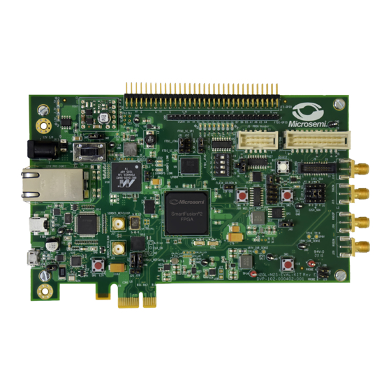
Page 28: Appendix: Smartfusion2 Security Evaluation Kit Board
Appendix: SmartFusion2 Security Evaluation Kit Board Appendix: SmartFusion2 Security Evaluation Kit Board The following figure shows the SmartFusion2 Security Evaluation Kit board. Figure 29 • SmartFusion2 Security Evaluation Kit Board DG0584 Demo Guide Revision 5.0... -
Page 29: Appendix: Error Codes
Appendix: Error Codes Appendix: Error Codes The following table lists the information about the error codes. Table 4 • Error Codes Define Error Code Description #define MSS_SYS_CHAINING_MISMATCH Device contents mismatch #define MSS_SYS_UNEXPECTED_DATA_RECEIVED Data is not supported #define MSS_SYS_INVALID_ENCRYPTION_KEY Invalid encryption key #define MSS_SYS_INVALID_COMPONENT_HEADER Invalid file #define MSS_SYS_BACK_LEVEL_NOT_SATISFIED... -
Page 30: Appendix: Generating .Spi Programming File Using Libero
Appendix: Generating .spi Programming File using Libero Appendix: Generating .spi Programming File using Libero The following steps describe how to generate .spi programming file using Libero: Launch the Libero SoC software to open a project for the iap_fabric_and_envm.spi programming file. The Libero design file is provided in <download_folder>\sf2_iap_using_interface_demo_df\smaple_programming_files\fabric_and_ envm. -
Page 31: Figure 32 Spi File Location
Appendix: Generating .spi Programming File using Libero Double-click Export Bitstream under Handoff Design for Production in the Design Flow tab to generate the .spi file. The following figure shows the .spi file location in Reports tab. Figure 32 • SPI File Location DG0584 Demo Guide Revision 5.0... -
Page 32: Appendix: Hardware Implementation
In this demo design, the following blocks are configured in Libero hardware project: • The SERDES_IF_1 in the SmartFusion2 device is configured for PCIe 2.0, x4 lanes, and Gen2 rate. • The CoreAHBLSRAM IP is configured to use the 4 KB of LSRAM. -
Page 33: Standby Clock Source Configuration
Appendix: Hardware Implementation Standby Clock Source Configuration The standby clock source for the MSS in the F*F mode is configured to On-chip 50 MHz RC Oscillator using the Flash*Freeze Hardware Settings dialog box in the Libero SoC software, as shown in the following figure. -
Page 34: Configuring I/Os For Flash*Freeze Mode
The FPGA fabric is not operational during the Program or Verify IAP operations as the device enters into the Flash*Freeze (F*F) mode. On the SmartFusion2 Security Evaluation Kit board, the SPI_0 is interfaced to the on-board SPI Flash memory for loading the programming bitstream data to the SPI Flash using the SPI interface. -
Page 35: Figure 37 Softconsole Project Workspace
Appendix: Hardware Implementation For software modifications, open the SoftConsole project workspace (located at <download_folder>\sf2_iap_using_interface_demo_df\libero\PCIE_IAP\SoftConsole4.0) using SoftConsole IDE v4.0. The following figure shows the SoftConsole project workspace. Figure 37 • SoftConsole Project Workspace The SoftConsole workspace consists the following projects: • PCIE_IAP_MSS_CM3_IAP_APP: Receives the bitstream from the host PC through the PCIe interface and invokes the system controller programming services. -
Page 36: Appendix: Implementing Workaround To Access Fabric Lsram After Iap/Isp Program
Appendix: Implementing Workaround to Access Fabric LSRAM after IAP/ISP Program Operation Appendix: Implementing Workaround to Access Fabric LSRAM after IAP/ISP Program Operation The LSRAM write and read accesses are denied after implementing the IAP or ISP program operation. The workaround for this problem is to apply System Reset after the IAP or ISP program operation. Changes Required in Libero Design 7.1.1 Option 1: Creating SmartDesign... -
Page 37: Figure 39 Tamper Macro Configuration Window
Appendix: Implementing Workaround to Access Fabric LSRAM after IAP/ISP Program Operation Figure 39 • Tamper Macro Configuration Window The following figure shows the TAMPER2_0 macro after configuration. Figure 40 • Tamper Macro - After Configuration Instantiate the FSM Module provided in the design files. This FSM logic performs three consecutive address writes to the two-port large SRAM with the known data pattern and then reads back data from those three consecutive address locations to compare. -
Page 38: Figure 41 Ram_Interafce Fsm Component
Appendix: Implementing Workaround to Access Fabric LSRAM after IAP/ISP Program Operation c. Click the Dev_Restart_after_IAP_blk tab and drag the Ram_interface component from the Design Hierarchy to the Dev_Restart_after_IAP_blk SmartDesign canvas. Figure 41 shows the Ram_interface component. Figure 41 • Ram_interafce FSM Component After the completion of the IAP programming, the System Controller asserts POWER_ON_RESET_n to the FPGA fabric. -
Page 39: Figure 42 Two-Port Sram Configurator Window
Appendix: Implementing Workaround to Access Fabric LSRAM after IAP/ISP Program Operation Figure 42 • Two-Port SRAM Configurator Window Connect Tamper Macro, FSM, and TPSRAM, as shown in the following figure. Figure 43 • Dev_Restart_after_IAP_blk SmartDesign Click the PCIE_IAP_top tab and drag the Dev_Restart_after_IAP_blk component from the Design Hierarchy to the PCIE_IAP_top SmartDesign canvas. -
Page 40: Option 2: Importing The .Cxf File In Libero Design
Appendix: Implementing Workaround to Access Fabric LSRAM after IAP/ISP Program Operation Connect the blocks as shown in the following figure and generate PCIE_IAP_top SmartDesign. This completes the implementation of the workaround. Figure 44 • PCIE_IAP_top SmartDesign Note: This workaround is applicable for v11.6 software release or later, and must be implemented in the Libero design, which is used to generate the .spi programming file.
Need help?
Do you have a question about the SmartFusion2 and is the answer not in the manual?
Questions and answers