Table of Contents
Advertisement
WARNING
Failure to follow all instructions and safety precautions in this
manual, in the Service Manual, in other manufacturers'
manuals and on the safety decals attached to the product could
result in serious injury or death to operators or bystanders and/
or damage to property.
DO NOT operate this vehicle before you READ and
UNDERSTAND this Operation Manual, the Service Manual for
this unit, other applicable manufacturers' manuals, and the
®
DuraPack
5000
safety decals on the product.
Each operator of this unit must read and understand all
HIGH-COMPACTION REAR LOADER
directions in this manual before they first operate this vehicle.
OPERATION MANUAL
Keep this manual in the cab for new operators and to remind all
operators about safe use.
ISSUED SEPTEMBER 2017
© 2017 Heil Environmental
TP1DP5-OM-0917
Advertisement
Table of Contents

Related Manuals for HEIL DuraPack 5000 2017

Summary of Contents for HEIL DuraPack 5000 2017
- Page 1 HIGH-COMPACTION REAR LOADER directions in this manual before they first operate this vehicle. OPERATION MANUAL Keep this manual in the cab for new operators and to remind all operators about safe use. ISSUED SEPTEMBER 2017 © 2017 Heil Environmental TP1DP5-OM-0917...
- Page 2 READ THIS MANUAL! EVERY PERSON who will OPERATE, MAINTAIN, REPAIR, OR OTHERWISE WORK with the Heil unit MUST READ AND UNDERSTAND this entire Operator’s Manual before starting the engine or activating any switches or controls. MAKE SURE to read the Service Manual for the unit BEFORE you do any maintenance or repair procedures.
-
Page 3: Table Of Contents
......................................32 General Safety Precautions (Continued) ....................................33 Decals ......................................36 Decal Placement ....................................37 Decal Images ....................................42 Reflective Safety Materials ....................................52 Care of Decals ....................................53 Lock-Out/Tag-Out Procedure Section Preview ......................................58 Issued September 2017 Copyright 2017, Heil Environmental Table of Contents Printed in U.S.A. - Page 4 Factory Body Props / Propping the Tailgate ......................................81 Propping the Tailgate (Continued) ......................................82 Daily Checklist Body Daily Checklist ......................................84 Refuse Vehicle Daily Inspection ......................................86 Daily Checks and Inspections ......................................87 Before Going on Route Issued September 2017 Copyright 2017, Heil Environmental Table of Contents Printed in U.S.A.
- Page 5 Loading Refuse with an Arm Mechanism (Continued) ....................................123 Loading Refuse with an Arm Mechanism (Continued) ....................................124 Loading Refuse with an Arm Mechanism (Continued) ....................................125 Loading Refuse with a Roll Bar Mechanism ......................................126 Issued September 2017 Copyright 2017, Heil Environmental Table of Contents Printed in U.S.A.
- Page 6 Preventive Maintenance Chart Body Preventive Maintenance Chart ......................................150 Lubrication Guide Body Lubrication Guide ......................................154 Body Lubrication Guide (Continued) ....................................155 Compressed Natural Gas (CNG) Option Important Safety Information ......................................158 Issued September 2017 Copyright 2017, Heil Environmental Table of Contents Printed in U.S.A.
- Page 7 CNG System Maintenance ......................................175 Inspection/Preventive Care Schedule / Preparation Before Maintenance ....................................176 Fuel Management Module Reference Drawing ....................................177 ....................................178 ......................................179 ....................................180 ....................................181 ....................................182 ....................................183 ....................................184 ....................................185 ....................................186 Issued September 2017 Copyright 2017, Heil Environmental Table of Contents Printed in U.S.A.
- Page 8 TABLE OF CONTENTS ....................................187 ....................................188 ..................................189 Index Issued September 2017 Copyright 2017, Heil Environmental Table of Contents Printed in U.S.A.
- Page 9 ® DuraPack 5000 ® DuraPack 5000 HIGH-COMPACTION REAR LOADER OPERATION MANUAL ISSUED SEPTEMBER 2017 TP1DP5-OM-0917 Issued September 2017 Copyright 2017, Heil Environmental Printed in U.S.A.
- Page 10 ® DuraPack 5000 NOTES:...
- Page 11 ® DuraPack 5000 SECTION 1 INTRODUCTION Issued September 2017 Copyright 2017, Heil Environmental Introduction Printed in U.S.A.
- Page 12 Telephone numbers and website URL for parts, technical support, warranty claims, training and manuals Identifying the different models Identifying the left (street side) of the unit The unit serial plate Various parts of the unit Issued September 2017 Copyright 2017, Heil Environmental Introduction Printed in U.S.A.
-
Page 13: Introduction
9. Landfill/Transfer Station/Recycle Center Procedures warranty repairs must be performed by …”. 10.End of Day Procedures Each DANGER, WARNING, and CAUTION notice 11.Preventive Maintenance Chart precedes its applicable text. 12.Lubrication Guide Issued September 2017 Copyright 2017, Heil Environmental Introduction Printed in U.S.A. -
Page 14: To The Owner
This manual is designed to help ensure safe, efficient and available for operation. proper operation of The Heil Co. d/b/a Heil Environmental You must provide adequate lighting on the unit for ®... -
Page 15: To The Operator
You must read, understand and obey all safety messages and decals that are on the outside or in the cab of the unit. Issued September 2017 Copyright 2017, Heil Environmental Introduction Printed in U.S.A. -
Page 16: To The Operator (Continued) / To The Mechanic
The owner or designated person can contact your Heil dealer or Heil for additional help. See Customer Service and Repair Parts Contact Information... - Page 17 You must read, understand, and obey all safety messages and decals that are on the outside or in the cab of the unit. Issued September 2017 Copyright 2017, Heil Environmental Introduction Printed in U.S.A.
-
Page 18: Warranty Claims And Inquiries
WARRANTY CLAIMS AND INQUIRIES The HEIL ENVIRONMENTAL WARRANTY STATEMENT is printed on the inside, back cover of this manual. Should a failure occur that is covered by this warranty, contact the nearest Heil dealer for warranty repair unless otherwise authorized by Heil. -
Page 19: Customer Service And Repair Parts Contact Information
5000 CUSTOMER SERVICE AND REPAIR PARTS CONTACT INFORMATION Customer Care Phone: 866-275-4345 Tech Services Phone: 866-310-4345 Parts Central Phone: 800-528-5308 4301 Gault Avenue North Fort Payne, AL 35967 www.heil.com Issued September 2017 Copyright 2017, Heil Environmental Introduction Printed in U.S.A. -
Page 20: Models
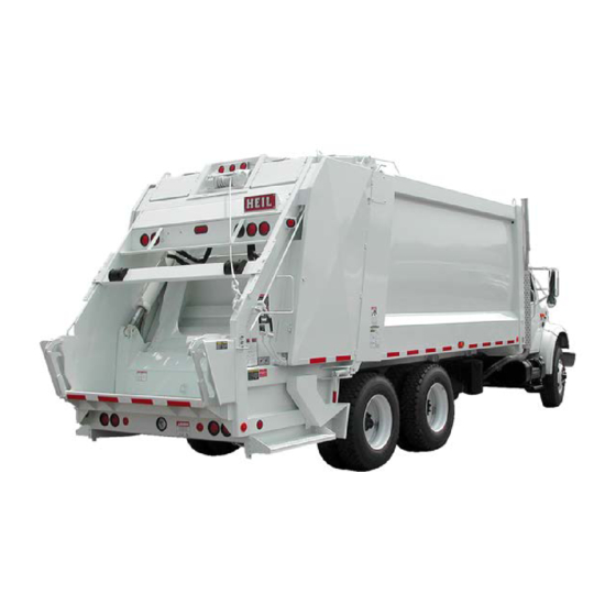
The unit has an eject mode for dumping the refuse from the body. You remove the refuse from the body by raising the tailgate and then operating the ejector panel which pushes the refuse from the body. Figure 1. Eject Model Issued September 2017 Copyright 2017, Heil Environmental Introduction Printed in U.S.A. -
Page 21: Serial Plate Location
“curbside”. The figure below shows the locations of the serial plates on the street side of the unit’s body and tailgate. See the next page for a description of the information that is on the serial plate. Figure 2. Serial Plate Locations Issued September 2017 Copyright 2017, Heil Environmental Introduction Printed in U.S.A. -
Page 22: Reading The Serial Plate
Date of manufacture (last number of the year followed by the number of the day of the year, e.g. 6145 is year 2006 and the 145th day of 2006). Issued September 2017 Copyright 2017, Heil Environmental Introduction Printed in U.S.A. -
Page 23: Product Nomenclature
The figure below shows the major components and their typical location on the unit. See the following pages for brief descriptions of each component shown below. Figure 4. Product Nomenclature (1 of 2) Issued September 2017 Copyright 2017, Heil Environmental Introduction Printed in U.S.A. -
Page 24: Product Nomenclature (Continued)
The figure below shows the major components and their typical location on the unit. See the following pages for brief descriptions of each component shown below. Figure 5. Product Nomenclature (2 of 2) Issued September 2017 Copyright 2017, Heil Environmental Introduction Printed in U.S.A. - Page 25 See Cab Controls, Switches and Indicator Lights for the different controls that may be installed in your unit. Issued September 2017 Copyright 2017, Heil Environmental Introduction Printed in U.S.A.
- Page 26 EXTEND the ejector panel, which pushes the refuse out of the unit. The operator then uses the controls to RETRACT the ejector panel and CLOSE the tailgate. Issued September 2017 Copyright 2017, Heil Environmental Introduction Printed in U.S.A.
- Page 27 Operating the unit’s controls with a suspended load, such as a raised tailgate or a container on a lift mechanism, will allow the load to move even when the hydraulic pump is OFF. Issued September 2017 Copyright 2017, Heil Environmental Introduction Printed in U.S.A.
- Page 28 Do not use an arm mechanism or roll bar as a riding step. Obey safety messages and use the riding step for when traveling on the unit. Serious injury or death may occur. Issued September 2017 Copyright 2017, Heil Environmental Introduction Printed in U.S.A.
- Page 29 Slide/Blade Controls – The operator uses these controls to operate the slide assembly and the packer blade to open the hopper to load refuse and to move refuse from the hopper into the body. Issued September 2017 Copyright 2017, Heil Environmental Introduction Printed in U.S.A.
- Page 30 Tailgate Cylinders – You use these cylinders to RAISE the tailgate before you unload the compacted refuse at the landfill. After you unload the refuse, you use the cylinders to LOWER the tailgate. Issued September 2017 Copyright 2017, Heil Environmental Introduction Printed in U.S.A.
- Page 31 Winch Assembly – The winch assembly includes a winch, an attached cable with hook and controls. This option allows an operator to load refuse from a commercial refuse container into the hopper. The controls will be located on the rear, curb side of the unit. Issued September 2017 Copyright 2017, Heil Environmental Introduction Printed in U.S.A.
-
Page 32: Glossary
An attachment to the tailgate of a Rear End Loader (REL) that an operator grabs with their hands handles) while using the riding step. harm An action that causes death, injury or property damage Issued September 2017 Copyright 2017, Heil Environmental Introduction Printed in U.S.A. - Page 33 The position of a switch or other control to stop a function When a light or lamp illuminates / on/ON The position of a switch or other control to start a function Issued September 2017 Copyright 2017, Heil Environmental Introduction Printed in U.S.A.
- Page 34 An option for Rear End Loaders (RELs), an assembly that uses a bar to lift, dump and lower a residential refuse bin Revolutions Per Minute Issued September 2017 Copyright 2017, Heil Environmental Introduction Printed in U.S.A.
- Page 35 Indicates a hazardous situation, which if not avoided, could result in death or serious injury. winch An option for Rear End Loaders (RELs), a mechanism with a hook and cable that an operator uses to raise, dump and lower a commercial refuse container Issued September 2017 Copyright 2017, Heil Environmental Introduction Printed in U.S.A.
- Page 36 ® DuraPack 5000 NOTES:...
-
Page 37: Safety Messages And Decals
® DuraPack 5000 SECTION 2 SAFETY MESSAGES AND DECALS Issued September 2017 Copyright 2017, Heil Environmental Safety Messages and Decals Printed in U.S.A. - Page 38 General safety precautions and safety precautions for the safe operation and maintenance of the unit The safety precautions for NOT towing another vehicle or machine Safety decals on the unit Issued September 2017 Copyright 2017, Heil Environmental Safety Messages and Decals Printed in U.S.A.
-
Page 39: Precautionary Statements
You must also read, understand and follow those messages. Issued September 2017 Copyright 2017, Heil Environmental Safety Messages and Decals Printed in U.S.A. -
Page 40: General Safety Precautions
If any decals are illegible from switch so it shuts off the pump. damage or wear, REPLACE them IMMEDIATELY. Get decals from your Heil dealer or Heil. o For units with automatic transmissions PUSH the SYSTEM POWER switch so the pump shuts off. - Page 41 CHECK the height of the unit after you do any modifications to the chassis suspension. Any chassis suspension modification may change the height of the unit. See Tables 1 and 2. Issued September 2017 Copyright 2017, Heil Environmental Safety Messages and Decals Printed in U.S.A.
- Page 42 4 feet (1.2 m) Above 750 to 50,000 6 feet (1.8 m) Above 50,000 to 345,000 10 feet (3 m) Above 345,000 to 750,000 16 feet (4.9 m) Issued September 2017 Copyright 2017, Heil Environmental Safety Messages and Decals Printed in U.S.A.
- Page 43 TOWING OF ANY EQUIPMENT Heil DOES NOT recommend that you tow any kind of equipment with the unit. The unit was NOT DESIGNED nor intended for towing. Issued September 2017...
-
Page 44: Decals
Decal part numbers can be found below and in the Parts Manual. You can purchase replacement decals from your Heil Dealer or from the Heil Parts Central, 800- 528-5308. -
Page 45: Decal Placement
® DuraPack 5000 DECAL PLACEMENT Issued September 2017 Copyright 2017, Heil Environmental Safety Messages and Decals Printed in U.S.A. - Page 46 ® DuraPack 5000 DECAL PLACEMENT (CONTINUED) Issued September 2017 Copyright 2017, Heil Environmental Safety Messages and Decals Printed in U.S.A.
- Page 47 ® DuraPack 5000 DECAL PLACEMENT (CONTINUED) Issued September 2017 Copyright 2017, Heil Environmental Safety Messages and Decals Printed in U.S.A.
- Page 48 ® DuraPack 5000 DECAL PLACEMENT (CONTINUED) Issued September 2017 Copyright 2017, Heil Environmental Safety Messages and Decals Printed in U.S.A.
- Page 49 DECAL, Danger, Access Door Closed ..........- ......1 212-1780 DECAL, Caution, Side Door ..............- ......1 212-1915 DECAL, Information-Heil Replacement Parts ........- ......1 212-1909 DECAL, Warning, Overall Height ............- ......1 212-1918 DECAL, Safety Instructions, Back-Up Alarm ........- ......1 212-1968 DECAL, Caution, Disengage PTO ............
-
Page 50: Decal Images
® DuraPack 5000 DECAL IMAGES Figure 7. Danger: Stand clear tailgate, PN 212-1801 Figure 6. Warning: Control Lever Operation, PN 212-1541 Issued September 2017 Copyright 2017, Heil Environmental Safety Messages and Decals Printed in U.S.A. - Page 51 Figure 8. Warning: Lock-out / Tag-out, PN 212-1781 Figure 9. Warning: Operations manual, PN 212-1783 Figure 10. Danger: Do not enter under, PN 212-1764 Figure 11. Danger: Stand clear packer, PN 212-1802 Issued September 2017 Copyright 2017, Heil Environmental Safety Messages and Decals Printed in U.S.A.
- Page 52 Figure 12. Caution: Riding Step Speed panel, PN 212-1911 Limit, PN 212-1905 Figure 14. Hydraulic Oil Only, PN 212-1782 Figure 15. Danger: Not for towing, PN 212-1821 Issued September 2017 Copyright 2017, Heil Environmental Safety Messages and Decals Printed in U.S.A.
- Page 53 Figure 17. Danger: Stay clear container, PN 212-1899 Figure 16. Warning: Do not Figure 18. Danger: Keep access door cross/stand behind, PN closed, PN 212-1907 212-2691 Issued September 2017 Copyright 2017, Heil Environmental Safety Messages and Decals Printed in U.S.A.
- Page 54 Figure 20. Warning: Figure 19. Caution: Side access door only, PN 212-1780 Overall height, PN 212-1909 Figure 21. Buzzer, PN 212-1903 Figure 22. Caution: Disengage P.T.O., PN 212-1968 Issued September 2017 Copyright 2017, Heil Environmental Safety Messages and Decals Printed in U.S.A.
- Page 55 Figure 23. Safety Requirements, ANSI, PN 212-1841 Figure 24. Throttle Advance, ANSI, PN 212-1904 Figure 25. Tailgate/Ejector Figure 26. Blade/Slide Controls, PN 212-1969 Operation, PN 212-1906 Issued September 2017 Copyright 2017, Heil Environmental Safety Messages and Decals Printed in U.S.A.
- Page 56 Figure 27. Caution, Riding Step, ANSI, PN 212-1902 Figure 28. Flag, Made in USA, PN 212-2689 Figure 29. Oil Level, PN Figure 30. Container Dump 212-2275 Mechanism Controls, PN 212-1838 Issued September 2017 Copyright 2017, Heil Environmental Safety Messages and Decals Printed in U.S.A.
- Page 57 Figure 32. Heil Mechanism Controls, Replacement Parts, PN PN 212-1839 212-1915 Figure 34. Tailgate Raise Alarm, PN 212-1970 Figure 33. Safety Instructions, Back-Up Alarm, PN 212-1918 Issued September 2017 Copyright 2017, Heil Environmental Safety Messages and Decals Printed in U.S.A.
- Page 58 ® DuraPack 5000 DECAL IMAGES (CONTINUED) Figure 35. Caution: Tailgate Prop Operation, PN 212-2791 Issued September 2017 Copyright 2017, Heil Environmental Safety Messages and Decals Printed in U.S.A.
- Page 59 ® DuraPack 5000 DECAL IMAGES (CONTINUED) Figure 36. Lubrication Guide, PN 212-1542 Issued September 2017 Copyright 2017, Heil Environmental Safety Messages and Decals Printed in U.S.A.
-
Page 60: Reflective Safety Materials
When you replace a part that had safety material on it, make sure you install new safety material on the new replacement part. See the Parts and Service Manual for all part numbers and location of the safety materials. You can purchase replacement decals from your Heil Dealer or from the Heil Parts Central, 800-528-5308. Issued September 2017... -
Page 61: Care Of Decals
Do not use sharp angles to clean the decals – this can lift the decals from the unit. o NEVER use a “turbo pressure nozzle”. Issued September 2017 Copyright 2017, Heil Environmental Safety Messages and Decals Printed in U.S.A. - Page 62 ® DuraPack 5000 PRESSURE WASHER TECHNIQUE Figure 37. Recommended Technique Figure 38. Incorrect Technique Issued September 2017 Copyright 2017, Heil Environmental Safety Messages and Decals Printed in U.S.A.
- Page 63 Flush eyes and skin with water for 15 minutes after contact. Seek immediate medical help. Spot clean the decal with Isopropyl Alcohol and a micro-fiber cloth (rag). If these methods do not work on a problem area, call a Heil Dealer or Heil Customer Service. Issued September 2017...
- Page 64 ® DuraPack 5000 NOTES:...
-
Page 65: Lock-Out/Tag-Out Procedure
® DuraPack 5000 SECTION 3 LOCK-OUT/TAG-OUT PROCEDURE Issued September 2017 Copyright 2017, Heil Environmental Lock-Out/Tag-Out Procedure Printed in U.S.A. - Page 66 DuraPack 5000 PREVIEW Read this section to learn about the proper Lock-Out/Tag-Out procedures. You MUST Lock-Out/Tag-Out a unit BEFORE: You enter the body Do maintenance or repair procedures. Issued September 2017 Copyright 2017, Heil Environmental Lock-Out/Tag-Out Procedure Printed in U.S.A.
- Page 67 7. Put a LOCK-OUT/TAG-OUT tag onto the steering Out procedures, use the procedures that follow. Contact wheel. your supervisor or Heil Technical Service if you have any questions about Lock-Out/Tag-Out procedures. 8. Remove the ignition key from the cab, lock the vehicle, and put the key in a secure location.
- Page 68 ® DuraPack 5000 NOTES:...
- Page 69 ® DuraPack 5000 SECTION 4 FEATURES, CONTROLS, SWITCHES, AND INDICATOR LIGHTS Issued September 2017 Copyright 2017, Heil Environmental Controls, Switches, and Indicator Lights Printed in U.S.A.
- Page 70 Learn about the unit's features and operation specifications The in-cab cab controls, switches and buttons How the in-cab controls work The in-cab indicator lights available The outside controls and how they work Issued September 2017 Copyright 2017, Heil Environmental Controls, Switches, and Indicator Lights Printed in U.S.A.
-
Page 71: Controls, Switches, And Indicator Lights
Make sure you are familiar with the control panel in your unit. Figure 40. In-Cab Control Panel Issued September 2017 Copyright 2017, Heil Environmental Controls, Switches, and Indicator Lights Printed in U.S.A. -
Page 72: In-Cab Control Panel (Continued)
FILTER BYPASSED indicator light and it is Throttle Advance switches on the body. OFF. MOVE the switch to the OFF position to disable the Throttle Advance switches on the body. Issued September 2017 Copyright 2017, Heil Environmental Controls, Switches, and Indicator Lights Printed in U.S.A. - Page 73 You must become familiar with the location and operation of any optional toggle switches that are not located in the Control Panel. Figure 42. Control Panel Optional Functions Issued September 2017 Copyright 2017, Heil Environmental Controls, Switches, and Indicator Lights Printed in U.S.A.
-
Page 74: Standard Outside Controls
UPPER PANEL lever. It is the lever closest to the end of c. MOVE and COMPACT the refuse in the hopper to the tailgate. See the figures on the next two pages. the body. Issued September 2017 Copyright 2017, Heil Environmental Controls, Switches, and Indicator Lights Printed in U.S.A. -
Page 75: Standard Outside Controls (Continued)
® DuraPack 5000 STANDARD OUTSIDE CONTROLS (CONTINUED) Figure 43. Blade Control Lever Issued September 2017 Copyright 2017, Heil Environmental Controls, Switches, and Indicator Lights Printed in U.S.A. - Page 76 ® DuraPack 5000 STANDARD OUTSIDE CONTROLS (CONTINUED) Figure 44. Upper Panel Control Lever Issued September 2017 Copyright 2017, Heil Environmental Controls, Switches, and Indicator Lights Printed in U.S.A.
-
Page 77: Standard Outside Controls (Continued)
® DuraPack 5000 STANDARD OUTSIDE CONTROLS (CONTINUED) Figure 45. Normal Loading Cycle Issued September 2017 Copyright 2017, Heil Environmental Controls, Switches, and Indicator Lights Printed in U.S.A. -
Page 78: Standard Outside Controls (Continued)
3. RELEASE the lever to stop an EXTEND or a RETRACT operation at any time or when the ejector panel is fully EXTENDED or RETRACTED. Issued September 2017 Copyright 2017, Heil Environmental Controls, Switches, and Indicator Lights Printed in U.S.A. -
Page 79: Standard Outside Controls (Continued)
This means that you observe the safety message for using the riding step. Figure 46. Front Street Side Controls Figure 47. Buzzer Switch Location Issued September 2017 Copyright 2017, Heil Environmental Controls, Switches, and Indicator Lights Printed in U.S.A. - Page 80 If equipped, use this switch to turn on the Hopper Light. See the figure to the right. Figure 48. Buzzer and Hopper Light Switch Location Issued September 2017 Copyright 2017, Heil Environmental Controls, Switches, and Indicator Lights Printed in U.S.A.
-
Page 81: Optional Outside Controls
The increased flow of hydraulic oil increases the speed of the optional lifting equipment. Figure 50. Optional Container Lift Controls (2 of 2) Issued September 2017 Copyright 2017, Heil Environmental Controls, Switches, and Indicator Lights Printed in U.S.A. -
Page 82: Optional Outside Controls (Continued)
1. PUSH the lever to the LOWER position and HOLD it and lower the container to the ground. there to MOVE the cylinder OUT (EXTEND). Issued September 2017 Copyright 2017, Heil Environmental Controls, Switches, and Indicator Lights Printed in U.S.A. -
Page 83: Optional Outside Controls (Continued)
5. PULL/PUSH the lever to RAISE the container over and lower the container to the ground. the hopper lip, dump the refuse from the container and lower the container to the ground. Issued September 2017 Copyright 2017, Heil Environmental Controls, Switches, and Indicator Lights Printed in U.S.A. - Page 84 RELEASE the lever to LOWER the cart tipper. At the end of the LOWER cycle, the cart tipper will stop lowering. 7. RELEASE the refuse container from the cart tipper’s lock. Issued September 2017 Copyright 2017, Heil Environmental Controls, Switches, and Indicator Lights Printed in U.S.A.
- Page 85 4. A “bash bar” prevents the container from over- Figure 52. Latch Bar Assembly rotating into the hopper. Issued September 2017 Copyright 2017, Heil Environmental Controls, Switches, and Indicator Lights Printed in U.S.A.
- Page 86 ® DuraPack 5000 NOTES:...
-
Page 87: Body And Tailgate Props
® DuraPack 5000 SECTION 5 BODY AND TAILGATE PROPS Issued September 2017 Copyright 2017, Heil Environmental Body and Tailgate Props Printed in U.S.A. - Page 88 ® DuraPack 5000 PREVIEW Read this section to learn about: Using the body props Using the tailgate props Issued September 2017 Copyright 2017, Heil Environmental Body and Tailgate Props Printed in U.S.A.
-
Page 89: Propping The Tailgate (Continued)
Figure 53. Tailgate Clamps (Turnbuckles) Issued September 2017 Copyright 2017, Heil Environmental Body and Tailgate Props Printed in U.S.A. - Page 90 ® DuraPack 5000 Issued September 2017 Copyright 2017, Heil Environmental Body and Tailgate Props Printed in U.S.A.
-
Page 91: Daily Checklist
® DuraPack 5000 SECTION 6 DAILY CHECKLIST Issued September 2017 Copyright 2017, Heil Environmental Daily Checklist Printed in U.S.A. - Page 92 Worn or damaged tailgate lock components Replace worn or damaged components Loose or missing tailgate lock hardware Tighten loose hardware Replace missing hardware Damaged tailgate seal Replace seal Issued September 2017 Copyright 2017, Heil Environmental Daily Checklist Printed in U.S.A.
- Page 93 Body mounting brackets have loose hardware, Tighten loose hardware damaged hardware or cracked welds Replace missing hardware Repair cracked welds Air regulator (typically located at front of body) 90 PSI Issued September 2017 Copyright 2017, Heil Environmental Daily Checklist Printed in U.S.A.
-
Page 94: Refuse Vehicle Daily Inspection
Refer to Preventative Maintenance Chart Signature of Operator: Lubrication Guide additional information and requirements. ________________________________________________________ Issued September 2017 Copyright 2017, Heil Environmental Daily Checklist Printed in U.S.A. - Page 95 Inspect all decals on cab for damage and readability. Inspect unit for refuse on or about the engine or exhaust components. Remove all refuse to prevent a fire. BODY AND CHASSIS CURB SIDE INSPECTION Issued September 2017 Copyright 2017, Heil Environmental Daily Checklist Printed in U.S.A.
- Page 96 Cylinder for damage Loose or missing mounting hardware Inspect tailgate lock components Clamp components for wear and damage Loose or missing mounting hardware Make sure tailgate is locked Issued September 2017 Copyright 2017, Heil Environmental Daily Checklist Printed in U.S.A.
- Page 97 Cylinders, hoses and fittings for leaks Hoses for wear and damage Cylinder for damage Loose or missing mounting hardware for hydraulics Loose or missing hardware for packer blade Issued September 2017 Copyright 2017, Heil Environmental Daily Checklist Printed in U.S.A.
- Page 98 Inspect body structure for damage, loose or missing nuts and bolts and for cracked welds. Inspect body mounting brackets for cracked weld, missing bolts or nuts or movement. Issued September 2017 Copyright 2017, Heil Environmental Daily Checklist Printed in U.S.A.
- Page 99 Make sure the backup alarm and light operate. Make sure all people not necessary and any hazards are clear of the area and then: Operate the in-cab controls and make sure: Issued September 2017 Copyright 2017, Heil Environmental Daily Checklist Printed in U.S.A.
- Page 100 At the same time, PULL the SLIDE and BLADE levers The blade should move UP The slide should move OUT Operate each installed optional outside control located at the tailgate: Reeving Mechanism Issued September 2017 Copyright 2017, Heil Environmental Daily Checklist Printed in U.S.A.
- Page 101 PULL the control lever – the roll bar should RAISE PUSH the control lever – the roll bar should LOWER Make sure the roll bar is at the full LOWER position Issued September 2017 Copyright 2017, Heil Environmental Daily Checklist Printed in U.S.A.
- Page 102 Store the tailgate props and RAISE the tailgate completely PULL the ejector lever and FULLY EXTEND the ejector panel PUSH the ejector lever and FULLY RETRACT the ejector panel CLOSE the tailgate Issued September 2017 Copyright 2017, Heil Environmental Daily Checklist Printed in U.S.A.
- Page 103 If equipped, check the operation of each camera. FINAL INSPECTION While you walk completely around the vehicle, look for: Fluid Leaks Cracked or damaged welds and metal Loose or missing bolts, nuts and clamps Issued September 2017 Copyright 2017, Heil Environmental Daily Checklist Printed in U.S.A.
- Page 104 ® DuraPack 5000 NOTES:...
-
Page 105: Before Going On Route
® DuraPack 5000 SECTION 7 BEFORE GOING ON ROUTE Issued September 2017 Copyright 2017, Heil Environmental Before Going on Route Printed in U.S.A. - Page 106 Checking the unit each day Starting the unit in cold weather Setting the unit up for the route Removing power to the unit during periods of not using the unit Issued September 2017 Copyright 2017, Heil Environmental Before Going on Route Printed in U.S.A.
-
Page 107: Battery Disconnect Switch / Daily Checklist
Battery cables must be securely anchored and not rubbing other equipment. Cable insulation must be free of damage and abrasion. Inspect weekly. NOTICE Always disconnect the battery before welding on the chassis or body. Issued September 2017 Copyright 2017, Heil Environmental Before Going on Route Printed in U.S.A. - Page 108 6. Make sure the oil temperature on the site gauge is between 120° and 160°F. If not, repeat step 5. 7. Check for fluid leaks. Repair if necessary. Issued September 2017 Copyright 2017, Heil Environmental Before Going on Route Printed in U.S.A.
-
Page 109: Check The Hydraulic Oil Level
200 mesh (or finer) 2. Put the unit back in the position described above and screen. NEVER use a cloth to filter the oil. check the oil level again. Issued September 2017 Copyright 2017, Heil Environmental Before Going on Route Printed in U.S.A. -
Page 110: Hydraulic Oil Tank With Sight Gauge
® DuraPack 5000 HYDRAULIC OIL TANK WITH SIGHT GAUGE Figure 54. Hydraulic Oil Tank with Sight Gauge Issued September 2017 Copyright 2017, Heil Environmental Before Going on Route Printed in U.S.A. -
Page 111: Cycle All Hydraulic Functions
UNLOCK and RAISE the tailgate, then do at least one EJECTOR PANEL cycle, which includes a full EXTEND cycle and a full RETRACT cycle. Issued September 2017 Copyright 2017, Heil Environmental Before Going on Route Printed in U.S.A. -
Page 112: Check The Traveling Or "In-Transit" Position
The PUMP ON switch is OFF. You properly ADJUST and CLEAN the mirrors. All outside lights turn ON and OFF. If equipped, the side access door is CLOSED and LOCKED. Issued September 2017 Copyright 2017, Heil Environmental Before Going on Route Printed in U.S.A. -
Page 113: Check The Traveling Or "In-Transit" Position (Continued)
® DuraPack 5000 CHECK THE TRAVELING OR “IN-TRANSIT” NOTES: POSITION (CONTINUED) Figure 56. In-Transit Position (Door Details) Issued September 2017 Copyright 2017, Heil Environmental Before Going on Route Printed in U.S.A. - Page 114 ® DuraPack 5000 NOTES:...
-
Page 115: On-Route Operation Procedures
® DuraPack 5000 SECTION 8 ON-ROUTE OPERATION PROCEDURES Issued September 2017 Copyright 2017, Heil Environmental On-Route Operation Procedures Printed in U.S.A. - Page 116 Read this section to learn about: Setting up the unit for a route Loading refuse Packing the load Packing on-the-move Washout system Setting up the unit for the landfill or transfer station Issued September 2017 Copyright 2017, Heil Environmental On-Route Operation Procedures Printed in U.S.A.
-
Page 117: Driving To Pick-Up Locations
Failure to obey may result in minor or moderate injury. You properly ADJUST and CLEAN the mirrors. All outside lights turn ON and OFF. If equipped, the side access door is CLOSED and LOCKED. Issued September 2017 Copyright 2017, Heil Environmental On-Route Operation Procedures Printed in U.S.A. -
Page 118: Before Loading (Continued)
The hopper is now ready to receive refuse. 2. Load the refuse from a container into the hopper and then move the container to the pick-up location. Figure 57. Packer Blade Starting Position Issued September 2017 Copyright 2017, Heil Environmental On-Route Operation Procedures Printed in U.S.A. -
Page 119: Loading Refuse Manually (Continued)
6. Repeat Steps 1 and 5 as necessary to compact the refuse. 7. Leave the blade against the refuse. 8. Move the refuse container to its pick-up location. Figure 58. Loading Refuse Issued September 2017 Copyright 2017, Heil Environmental On-Route Operation Procedures Printed in U.S.A. - Page 120 Clear the area of all unnecessary people before you operate the controls. Issued September 2017 Copyright 2017, Heil Environmental On-Route Operation Procedures Printed in U.S.A.
-
Page 121: Loading Refuse With A Reeving Mechanism
Issued September 2017 Copyright 2017, Heil Environmental On-Route Operation Procedures Printed in U.S.A. -
Page 122: Loading Refuse With A Reeving Mechanism (Continued)
Make sure the latch bar secures the container until the cable tightens and secures the hook in BEFORE you raise the container. See Using a the eye on the tailgate. Latch Bar Issued September 2017 Copyright 2017, Heil Environmental On-Route Operation Procedures Printed in U.S.A. -
Page 123: Loading Refuse With A Reeving Mechanism (Continued)
See Using a Latch Bar i. MOVE the container to its pick-up location. Figure 60. Reeving Mechanism or Winch Setup Figure 61. Loading Refuse with Reeving Mechanism or Winch Issued September 2017 Copyright 2017, Heil Environmental On-Route Operation Procedures Printed in U.S.A. - Page 124 Figure 62. Loading Refuse with Reeving blade is at the pinch point with the hopper sill. Mechanism or Winch c. Watch for refuse that is pushed out of the hopper. Issued September 2017 Copyright 2017, Heil Environmental On-Route Operation Procedures Printed in U.S.A.
- Page 125 5. Leave the blade against the refuse. the tailgate and let the driver know each helper is ready to move to the next location. 7. Go to the next stop on the route. Issued September 2017 Copyright 2017, Heil Environmental On-Route Operation Procedures Printed in U.S.A.
-
Page 126: Loading Refuse With A Winch
Clear the area near the hopper of all unnecessary people before you move the blade and upper panel and keep all parts of your body away from the blade. Issued September 2017 Copyright 2017, Heil Environmental On-Route Operation Procedures Printed in U.S.A. -
Page 127: Loading Refuse With A Winch (Continued)
(2) Lower the container to the ground (3) Perform Step 3 (sweep the refuse and compact it into the hopper) (4) Raise the container and finish emptying the container. Issued September 2017 Copyright 2017, Heil Environmental On-Route Operation Procedures Printed in U.S.A. -
Page 128: Loading Refuse With A Winch (Continued)
RELEASE the levers. The levers will self-center at the end of the commanded position by way of valve internal hydraulic pressure. See Figure 44 Issued September 2017 Copyright 2017, Heil Environmental On-Route Operation Procedures Printed in U.S.A. - Page 129 7. Each helper must PRESS the buzzer on their side of the tailgate and let the driver know each helper is ready to move to the next location. 8. Go to the next stop on the route. Issued September 2017 Copyright 2017, Heil Environmental On-Route Operation Procedures Printed in U.S.A.
-
Page 130: Loading Refuse With An Arm Mechanism
(4) RAISE the container and finish emptying the container. b. The upper panel will move IN and the blade will move DOWN. c. The hopper is now ready to receive refuse. Issued September 2017 Copyright 2017, Heil Environmental On-Route Operation Procedures Printed in U.S.A. -
Page 131: Loading Refuse With An Arm Mechanism (Continued)
MOVE the container to its pick-up location. Figure 63. Arm Mechanism Setup Figure 64. Loading Refuse with Arm Mechanism Issued September 2017 Copyright 2017, Heil Environmental On-Route Operation Procedures Printed in U.S.A. - Page 132 The upper panel will move OUT and the blade will Figure 65. Loading Refuse with Arm Mechanism move UP. STOP the blade UP operation when the blade is at the pinch point with the hopper sill. Issued September 2017 Copyright 2017, Heil Environmental On-Route Operation Procedures Printed in U.S.A.
- Page 133 Do not use an arm mechanism or roll bar as a riding step. Obey safety messages and use the riding step for when traveling on the unit. Serious injury or death may occur. Issued September 2017 Copyright 2017, Heil Environmental On-Route Operation Procedures Printed in U.S.A.
-
Page 134: Loading Refuse With A Roll Bar Mechanism
The hopper is now ready to receive refuse. bar before you raise or lower the container. Issued September 2017 Copyright 2017, Heil Environmental On-Route Operation Procedures Printed in U.S.A. -
Page 135: Loading Refuse With A Roll Bar Mechanism (Continued)
RELEASE the container’s trunnion bar from the latch bar. See Using a Latch Bar g. RELEASE the container from the roll bar mechanism. Issued September 2017 Copyright 2017, Heil Environmental On-Route Operation Procedures Printed in U.S.A. - Page 136 ® DuraPack 5000 LOADING REFUSE WITH A ROLL BAR MECHANISM (CONTINUED) Figure 66. Roll Bar Setup Figure 67. Loading Refuse with Roll Bar Issued September 2017 Copyright 2017, Heil Environmental On-Route Operation Procedures Printed in U.S.A.
- Page 137 7. Go to the next stop on the route. Figure 68. Loading Refuse with a Roll Bar Issued September 2017 Copyright 2017, Heil Environmental On-Route Operation Procedures Printed in U.S.A.
-
Page 138: Loading Refuse With A Cart Tipper
Make sure the refuse container is properly secured to the cart tipper before you raise or lower the container. Issued September 2017 Copyright 2017, Heil Environmental On-Route Operation Procedures Printed in U.S.A. -
Page 139: Loading Refuse With A Cart Tipper (Continued)
Clear the area near the hopper of all unnecessary people before you move the blade and upper panel and keep all parts of your body away from the blade. Issued September 2017 Copyright 2017, Heil Environmental On-Route Operation Procedures Printed in U.S.A. - Page 140 Watch for refuse that is pushed out of the hopper. Figure 71. Loading Refuse with Cart Tipper Issued September 2017 Copyright 2017, Heil Environmental On-Route Operation Procedures Printed in U.S.A.
-
Page 141: Loading Refuse With A Cart Tipper (Continued) / Using A Latch Bar
7. Go to the next stop on the route. lowering operations. See Figure 59 4. The bash bar prevents the container from over- rotating into the hopper. Issued September 2017 Copyright 2017, Heil Environmental On-Route Operation Procedures Printed in U.S.A. -
Page 142: Using A Latch Bar (Continued)
® DuraPack 5000 USING A LATCH BAR (CONTINUED) Figure 73. Latch Bars Rotated Up Figure 72. Latch Bars Rotated Down Issued September 2017 Copyright 2017, Heil Environmental On-Route Operation Procedures Printed in U.S.A. -
Page 143: Packing On-The-Move
MPH or to travel more than 2 tenths (0.2) of a mile. Do not material also helps lubricate the body, which results use riding step when vehicle operates in reverse. Always in better packing. face vehicle when using riding step. Issued September 2017 Copyright 2017, Heil Environmental On-Route Operation Procedures Printed in U.S.A. -
Page 144: Leaving The Route For The Landfill/Transfer Station
The PUMP ON switch is OFF. You properly ADJUST and CLEAN the mirrors. All outside lights turn ON and OFF. If equipped, the side access door is CLOSED and LOCKED. Issued September 2017 Copyright 2017, Heil Environmental On-Route Operation Procedures Printed in U.S.A. -
Page 145: Landfill/Transfer Station/Recycle Center Procedures
® DuraPack 5000 SECTION 9 LANDFILL/TRANSFER STATION/ RECYCLE CENTER PROCEDURES Issued September 2017 Copyright 2017, Heil Environmental Landfill/Transfer Station/Recycle Center Procedures Printed in U.S.A. - Page 146 Read this section to learn about: Setup conditions to dump the refuse Unloading the refuse Using the sump and (optional) washout system Preparing the unit to return to route. Issued September 2017 Copyright 2017, Heil Environmental Landfill/Transfer Station/Recycle Center Procedures Printed in U.S.A.
-
Page 147: Overview Of Landfill/Transfer Station/Recycle Center Procedures
(at the front of the body) while you HOLD the stable, hard, dry and level surface you can find TAILGATE lever UP. before you empty the refuse. Issued September 2017 Copyright 2017, Heil Environmental Landfill/Transfer Station/Recycle Center Procedures Printed in U.S.A. - Page 148 PUSH the EJECT lever DOWN and HOLD until the ejector panel is fully RETRACTED and at the front of the body. b. RELEASE the eject lever. Figure 74. Raising the Tailgate Issued September 2017 Copyright 2017, Heil Environmental Landfill/Transfer Station/Recycle Center Procedures Printed in U.S.A.
- Page 149 Inspect the seal for possible wear or damage and replace if necessary. Figure 75. Unloading Refuse Issued September 2017 Copyright 2017, Heil Environmental Landfill/Transfer Station/Recycle Center Procedures Printed in U.S.A.
-
Page 150: Lower The Tailgate
The TAILGATE OPEN warning light will go OFF and the alarm will stop when body is FULLY down and the tailgate is completely closed. Figure 76. Lowering the Tailgate Issued September 2017 Copyright 2017, Heil Environmental Landfill/Transfer Station/Recycle Center Procedures Printed in U.S.A. -
Page 151: Locking The Tailgate
IMPORTANT! Inspect unit for refuse on or about the engine or exhaust components. Remove all refuse to If equipped, the side access door is CLOSED and prevent a fire. LOCKED. Issued September 2017 Copyright 2017, Heil Environmental Landfill/Transfer Station/Recycle Center Procedures Printed in U.S.A. - Page 152 ® DuraPack 5000 NOTES:...
-
Page 153: End Of Day Procedures
® DuraPack 5000 SECTION 11 END OF DAY PROCEDURES Issued September 2017 Copyright 2017, Heil Environmental End of Day Procedures Printed in U.S.A. -
Page 154: Parking The Unit
® DuraPack 5000 PREVIEW Read this section to learn about: Parking the Unit Washout System Final Inspection Report to Employer/Supervisor Ignition Keys Issued September 2017 Copyright 2017, Heil Environmental End of Day Procedures Printed in U.S.A. - Page 155 5. Check the unit for fluid leaks from the hoses, cylinders, valves, pump and fittings. Report any leaks to your employer/supervisor. Issued September 2017 Copyright 2017, Heil Environmental End of Day Procedures Printed in U.S.A.
- Page 156 ® DuraPack 5000 NOTES:...
-
Page 157: Preventive Maintenance Chart
® DuraPack 5000 SECTION 12 PREVENTIVE MAINTENANCE CHART Issued September 2017 Copyright 2017, Heil Environmental Preventive Maintenance Chart Printed in U.S.A. -
Page 158: Body Preventive Maintenance Chart
Electrical, Battery Cables Check for proper operation. Check battery cables from battery to starter for loose cables, rubbing or damage and abrasions to cables. Replace if necessary. Issued September 2017 Copyright 2017, Heil Environmental Preventive Maintenance Chart Printed in U.S.A. - Page 159 See Service Manual - Odyssey Cylinder Sensors Calibration. * Daily = 8 hrs. Weekly = 40 hrs. Monthly = 200 hrs. 6 Months = 1000 hrs. Yearly = 2000 hrs. Issued September 2017 Copyright 2017, Heil Environmental Preventive Maintenance Chart Printed in U.S.A.
- Page 160 ® DuraPack 5000 NOTES:...
-
Page 161: Lubrication Guide
® DuraPack 5000 SECTION 13 LUBRICATION GUIDE Issued September 2017 Copyright 2017, Heil Environmental Lubrication Guide Printed in U.S.A. - Page 162 Clean fittings before applying grease and always pump enough grease into joint to remove the old grease. Wipe off excess grease. Lubricate moveable mechanical parts without fittings every 60 days with non-detergent engine oil. Issued September 2017 Copyright 2017, Heil Environmental Lubrication Guide Printed in U.S.A.
- Page 163 Front Mount Drive Shaft Weekly/40 Hours Tailgate Turnbuckle Clamps Weekly/40 Hours Container Mech. Control: A. Handle Weekly/40 Hours B. Upper Pivot Weekly/40 Hours Ejector Cylinder (Not Shown) Weekly/40 Hours Issued September 2017 Copyright 2017, Heil Environmental Lubrication Guide Printed in U.S.A.
- Page 164 ® DuraPack 5000 NOTES:...
-
Page 165: Compressed Natural Gas (Cng) Option
® DuraPack 5000 SECTION 14 COMPRESSED NATURAL GAS (CNG) OPTION Issued September 2017 Copyright 2017, Heil Environmental Compressed Natural Gas (CNG) Option Printed in U.S.A. -
Page 166: Important Safety Information
Maintenance Manuals. Always read and understand all associated manuals alongside the Heil Operation Manual and Heil Parts and Service Manual before operating or servicing the unit. CNG training is required for any person inspecting, operating, or performing maintenance on a CNG unit. -
Page 167: Important Safety Information (Continued)
Keep work area well ventilated to avoid asphyxiation due to concentrated levels of carbon monoxide. WARNING Do not start the engine if a natural gas leak is detected. Issued September 2017 Copyright 2017, Heil Environmental Compressed Natural Gas (CNG) Option Printed in U.S.A. - Page 168 CAUTION Keep the compressed natural gas equipment area well ventilated. CAUTION A portable fire extinguisher must be installed on the vehicle in an accessible location. Issued September 2017 Copyright 2017, Heil Environmental Compressed Natural Gas (CNG) Option Printed in U.S.A.
-
Page 169: Compressed Natural Gas (Cng) Fuel Module
Manual and ignition controlled fuel shut-off Pressure reduction from storage tanks to engine supply Fuel system filtration Liquid removal from fuel system Issued September 2017 Copyright 2017, Heil Environmental Compressed Natural Gas (CNG) Option Printed in U.S.A. -
Page 170: Compressed Natural Gas (Cng) Fuel Module (Continued)
‘ON’ position to allow fuel flow from the tanks to the vehicle’s engine. Figure 78. Purge Valve Figure 77. Manual Shut-Off Valve Issued September 2017 Copyright 2017, Heil Environmental Compressed Natural Gas (CNG) Option Printed in U.S.A. - Page 171 CNG Fuel Module Maintenance and Part Replacement in the Compressed Natural Gas (CNG) section of your Service Manual. Figure 79. Side Maintenance Access Issued September 2017 Copyright 2017, Heil Environmental Compressed Natural Gas (CNG) Option Printed in U.S.A.
-
Page 172: Cng Vehicle Operator Emergency Response
5. Do not smoke or allow anyone else to smoke near the vehicle. 6. Turn the ignition switch off, set the parking brake and turn off the battery at the main disconnect. Issued September 2017 Copyright 2017, Heil Environmental Compressed Natural Gas (CNG) Option Printed in U.S.A. -
Page 173: Cng Vehicle Operator Emergency Response (Continued)
5. When completed, disconnect the on-board defueling 3. Close each Tank Valve. connection from the vent system and disconnect the 4. Call Technical Services at 866-310-4345 for further earth ground. assistance. Issued September 2017 Copyright 2017, Heil Environmental Compressed Natural Gas (CNG) Option Printed in U.S.A. -
Page 174: Cng Front Of Body / Top Of Body Decal Placement
In addition to the decal shown below, there may be other decals placed on the fuel management module (FMM), tank compartments or elsewhere on the CNG system components. Refer to the CNG System Manufacturer's Operation and Maintenance Manuals for replacement decal part numbers. Issued September 2017 Copyright 2017, Heil Environmental Compressed Natural Gas (CNG) Option Printed in U.S.A. -
Page 175: Starting Vehicle / Fueling Procedure
For tailgate mounted CNG, vent NOTICE lines route to the top of the tailgate. If the plastic caps are missing, contact Heil Parts Central for Optional, fill receptacles may be installed in a remote replacement caps (Part Number 042-2078 for 3/8"... -
Page 176: Fueling Procedure (Continued)
Figure 81. Type 1 Fueling Hoses again point toward each other (as shown in step "a"). You will hear a release of pressure. Issued September 2017 Copyright 2017, Heil Environmental Compressed Natural Gas (CNG) Option Printed in U.S.A. - Page 177 Begin fueling. e. When complete, release the locking lever and disconnect the fueling hose. Figure 82. Type 1 Fueling Hoses Figure 83. Type 2 Fueling Hose Issued September 2017 Copyright 2017, Heil Environmental Compressed Natural Gas (CNG) Option Printed in U.S.A.
-
Page 178: Transfer Fueling (Defueling) Modes, Components And Procedures (Continued)
ALWAYS ground (earth ground) the vehicle AND the fuel system being defueled NEVER defuel indoors Always wear personal protective equipment Be familiar with evacuation routes Issued September 2017 Copyright 2017, Heil Environmental Compressed Natural Gas (CNG) Option Printed in U.S.A. -
Page 179: Transfer Fueling (Defueling) Modes, Components And Procedures (Continued)
When the Defueling Control Valve is positioned to the “Defueling Enabled” position, CNG fuel from the storage tanks can flow to the Defueling Receptacle. Figure 86. Fuel Module Defueling Components Issued September 2017 Copyright 2017, Heil Environmental Compressed Natural Gas (CNG) Option Printed in U.S.A. - Page 180 Defueling Panel with a Defueling Receptacle. If your unit has the System option, the ignition must be left ON while defueling in order for all tanks to defuel. See Heil section for more information. Issued September 2017...
- Page 181 In this method, the vehicle is connected through the fueling nozzle to the defueling panel receptacle and the compressor at the fueling station extracts the compressed natural gas from the vehicle. Issued September 2017 Copyright 2017, Heil Environmental Compressed Natural Gas (CNG) Option Printed in U.S.A.
- Page 182 If venting to atmosphere, you must first check to see if this method is legal in your area as some natural gas will be vented along with the inert gas. Issued September 2017 Copyright 2017, Heil Environmental Compressed Natural Gas (CNG) Option Printed in U.S.A.
-
Page 183: Cng System Maintenance
Maintenance of a compressed natural gas system is to be performed ONLY by authorized service personnel. Unauthorized maintenance can result in personal injury and/or extensive damage to the unit. Issued September 2017 Copyright 2017, Heil Environmental Compressed Natural Gas (CNG) Option Printed in U.S.A. - Page 184 Follow the steps as outlined to ensure that no pressure remains. 1. Leave the Fuel Management Module Manual Shut- Off Valve in the ‘ON’ position. Issued September 2017 Copyright 2017, Heil Environmental Compressed Natural Gas (CNG) Option Printed in U.S.A.
-
Page 185: Fuel Management Module Reference Drawing
® DuraPack 5000 FUEL MANAGEMENT MODULE (FMM) REFERENCE DRAWING Component drawing for Heil 151-4764 Fuel Management Module is shown below. Figure 88. Fuel Management Module Issued September 2017 Copyright 2017, Heil Environmental Compressed Natural Gas (CNG) Option Printed in U.S.A. - Page 186 CNG cylinder inspections should be performed at a frequency of 3 years or 36,000 miles, whichever occurs first. 2. In addition, Heil recommends a daily walk-around or pre-trip and post-trip visual inspection be performed. Issued September 2017...
- Page 187 Summary of Features HEIL CNr Display screen inside the cab which gives live When equipped, the optional Heil CNrG Solenoid System pressure monitoring for each tank and system. will monitor and display live in-cab CNG system and tank Visual warning in form of messages and color on the Display.
- Page 188 The audible buzzer will be active regardless of ignition ON Figure 91. Multiple Pressure or ignition OFF and will not turn OFF until the issue is Transducer Sensors corrected. Unplugged/Faulty Issued September 2017 Copyright 2017, Heil Environmental Compressed Natural Gas (CNG) Option Printed in U.S.A.
- Page 189 OFF (ignition must be turned ON to see more details about the leak on the display screen). NOTICE Authorized Service Personnel should contact Heil Technical Service for the maintenance code to unlock the CNG solenoids. Figure 93. Alarm Summary...
- Page 190 Figure 95. Mutiple Tank Leaks. section of this manual. Maintenance Bypass Required. Figure 96. System Leak. Figure 94. Tank 1 Leak. Maintenance Bypass Required. Maintenance Bypass Required. Issued September 2017 Copyright 2017, Heil Environmental Compressed Natural Gas (CNG) Option Printed in U.S.A.
- Page 191 The audible buzzer will be active only when ignition is ON and will not turn OFF until the issue is corrected. Figure 98. Display Screenshot: Multiple Solenoids Failed Issued September 2017 Copyright 2017, Heil Environmental Compressed Natural Gas (CNG) Option Printed in U.S.A.
- Page 192 6. You will now be able to drive the truck to your maintenance department to evaluate and repair the leak. The audible alarm will not go OFF until the Authorized Service Personnel should contact Heil issue is corrected. Technical Service for the maintenance bypass code to unlock the CNG solenoids.
- Page 193 Low Fuel Warning alert message along with an audible alert. Figure 101. Display Screenshot: Tank Option Figure 100. Display Configuration Screenshot: Low Fuel Warning Issued September 2017 Copyright 2017, Heil Environmental Compressed Natural Gas (CNG) Option Printed in U.S.A.
- Page 194 Ignition Power (ON or OFF) and the system voltage the software revisions of the Cortex Display and Cortex Controller programs. Figure 103. Display Screenshot: System Outputs Figure 102. Display Screenshot: System Inputs Issued September 2017 Copyright 2017, Heil Environmental Compressed Natural Gas (CNG) Option Printed in U.S.A.
- Page 195 Ignition Power, which is required to open the Tank Solenoids Valves. Figure 105. Display Screenshot: System Over Voltage Figure 104. Display Screenshot: Ignition Power Issued September 2017 Copyright 2017, Heil Environmental Compressed Natural Gas (CNG) Option Printed in U.S.A.
- Page 196 5000 HEIL CNr Solenoid Failure (CONTINUED) Perform this procedure for any tank solenoid in the Heil System Under Voltage not needed for a system without solenoids. Refer to The display notification shown in the figure below will only Solenoid Failure Detection...
- Page 197 24, 31 check the hydraulic oil level ejector & tailgate controls clean and inspect the hopper and packer panel ejector lever clean and inspect the tailgate Issued September 2017 Copyright 2017, Heil Environmental Index Printed in U.S.A.
- Page 198 Heil CNrG Solenoid System defueling after solenoid failure factory body props Heil CNrG solenoid system option final inspection summary of features front head...
- Page 199 15, 16, 17 propping the tailgate 81, 82 notice 24, 31 Issued September 2017 Copyright 2017, Heil Environmental Index Printed in U.S.A.
- Page 200 17, 24 sight gauge slide (upper panel) assembly slide/blade controls unit standard indicator lights UNLATCHED standard outside controls 66, 67, 68, 69, 70, 71, 72 unloading Issued September 2017 Copyright 2017, Heil Environmental Index Printed in U.S.A.
- Page 201 133, 134 warming up the hydraulic oil warning 24, 31 warranty claims and inquiries washout system when working in or around the vehicle winch 24, 74 winch assembly Issued September 2017 Copyright 2017, Heil Environmental Index Printed in U.S.A.
- Page 202 ® DuraPack 5000 NOTES:...
- Page 203 Wear items are excluded from warranty coverage. All OEM service parts sold by Heil have a six (6) month warranty from the date of purchase. Aftermarket parts purchased from Heil are supported by a 90-day warranty. The parts warranty covers parts only, providing that factory inspection reveals a defect in material or workmanship.
- Page 204 Customer Care: 866-ASK-HEIL (866-275-4345) Heil Environmental 4301 Gault Avenue North Fort Payne, AL 35967-9984 Parts Central: 800-528-5308 Technical Service: 866-310-4345 TechSupport@DoverESG.com...
Need help?
Do you have a question about the DuraPack 5000 2017 and is the answer not in the manual?
Questions and answers