Sign In
Upload
Manuals
Brands
Toptech Manuals
Controller
MultiLoad II DIV-2
Toptech MultiLoad II DIV-2 Manuals
Manuals and User Guides for Toptech MultiLoad II DIV-2. We have
1
Toptech MultiLoad II DIV-2 manual available for free PDF download: Installation Manual
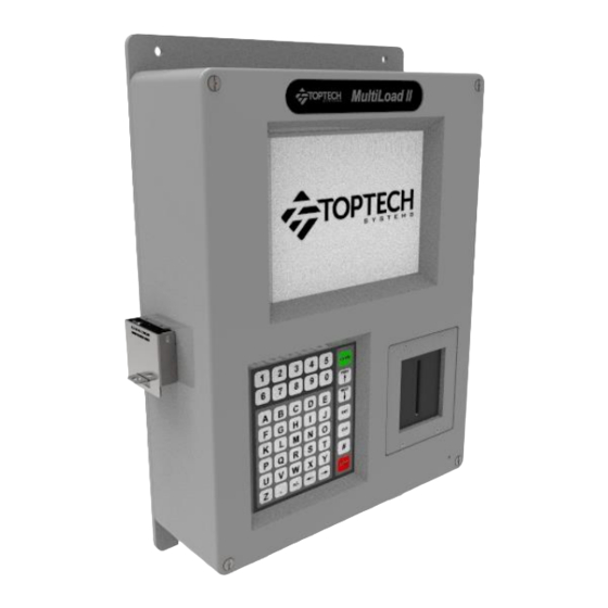
Toptech MultiLoad II DIV-2 Installation Manual (93 pages)
Flow Controller
Brand:
Toptech
| Category:
Controller
| Size: 2 MB
Table of Contents
Table of Contents
4
Overview
10
Chapter 1 General Information & Warnings
12
Receiving And/Or Returning Equipment
12
Safety Warnings
13
Electrostatic Discharge (ESD) Protection
14
FCC Note
15
Chapter 2 Operating Conditions and Components
16
Product Outline and Dimensions
16
Multiloadii/ RCUII - DIV2 Model - Picture
16
Figure 2.1 Multiload II (ML II) / Remote Control Unit II (RCU II) Division 2 Unit
16
Multiloadii/ RCUII - DIV2 Model - Dimensions
17
2.1.2.1 Front View
17
Figure 2.2 Unit Outline Drawing - Front View
17
2.1.2.2 Back View
18
Figure 2.3 Unit Outline Drawing - Back View
18
2.1.2.3 Bottom View
19
Figure 2.4 Unit Outline Drawing - Bottom View -2 Hole Base
19
Figure 2.5 Unit Outline Drawing - Bottom View - 5 Hole Base
19
2.1.2.4 Side View
20
Figure 2.6 Unit Outline Drawing - Side View
20
Operating Characteristics
21
Chapter 3 Installing the Multiload II/RCUII DIV2
23
Tools Required
23
Installation
23
Servicing and Repair
23
Cover Closure and Bolt Replacement
23
Cable Entries
23
Mounting the Multiload II/ RCU II DIV-2 Enclosure
23
Concrete or Cinder Block Walls
24
Drywall
24
Mounting Height Considerations
24
Wood
24
Figure 3.1 Suggested Mounting Position
25
Figure 3.2 Screen Visible Area
25
Recommended Wire Sizes and Torque for All Terminal Blocks
26
Electrical Supply Connections
26
AC Powered Models
27
DC Powered Models
27
Figure 3.3 Multiload II/ RCU II AC Power Supply/Comm Board
27
Equipment Grounding
28
Figure 3.4 DC Power Connections
28
Chapter 4 Data Communications Interface
29
Available Communications Protocol Selection and Wire Spec
30
Ethernet
31
Communication Connection Wiring
31
FCM I / FCM II Communications (Multiload II Product Only) - COM 0 -Port - RS485
31
COM 1 - RS-485 4-Wire - Host/Tms Communications
32
Figure 4.1 FCM / PCM Connections
32
Figure 4.2 RS485 4-Wire, Host to a Single Multiload II/ RCU II (Recommended)
32
Host/Tms Communications
32
4.2.2.2 COM 1 - RS-485 2-Wire: Host/Tms Communications
33
Figure 4.3 RS485 4-Wire, Host to Multiple Multiload II/ RCU Iis
33
Figure 4.4 RS485 2-Wire, Host to a Single Multiload II/ RCU II
33
4.2.2.3 COM 1 - RS-232 - Host/Tms Communications
34
Figure 4.5 RS485 4-Wire, Host to Multiple Multiload II/ RCU Iis
34
Figure 4.6 RS232, Host to a Single Multiload II/ RCU II
34
4.2.2.4 Ethernet - Host/Tms Communications
35
Figure 4.7 RS232, Host to Multiple Multiload II/ RCU Iis
35
Figure 4.8 Ethernet Connections
35
4.2.3.1 COM2 - RS232 - Host Ticket Printer/Data Logger
36
Figure 4.9 Ticket Printer / Data Logger Connections with Handshake
36
Host Ticket Printer/Data Logger
36
Figure 4.10 Ticket Printer / Data Logger Connections Without Handshake
37
Figure 4.11 PTB Printer Connection with Handshake
37
Chapter 5 Connecting Field Devices to the I/O Board
39
Where to Find the Internal I/O Board
39
Available I/O Points Per Board
40
Terminal Arrangements Per Board
42
Digital Analog I/O Board (IO_DA)
42
Meter I/O Board (IO-2M)
43
Figure 5.2 2 Meter I/O Board Terminal Block Assignments
43
How to Connect and Wire Field Devices to the I/O Boards
44
Multiload II Flow Meter and Control Valve Wiring
45
Multiload II Additive Wiring: Outputs
46
Multiload II Additive Wiring: Inputs
47
5.4.4.1 RTD Wiring
48
Multiload II Analog Wiring
48
5.4.4.2 Multiload II 4 - 20 Ma Wiring
49
Multiload II AC Output Wiring
50
Multiload II AC Input Wiring
51
Multiload II DC Permissive/Status Wiring
52
Multiload II DC Output Wiring
53
Multiload II 2 Output Air Eliminator Wiring
54
Multiload II Lectro Count Remote Display Wiring
55
RCU II DC Input Wiring
56
RCU II AC Output Wiring
57
RCU II DC Output Wiring
58
Typical 1 Meter Application Wiring Example IP&E Drawing (Electrical Wiring Schedule)
59
Chapter 6 Configurations
60
Switch Access Control
60
External Switch Access Control (Multiload II Only)
60
External Type 1 Program / W&M Switches
61
External Type 2 Program / W&M Switches
61
Figure 6.1 Type 1 Program / W&M Switches
61
Figure 6.2 Type 2 Program / W&M Switches
61
External Type 3 Program / W&M Switches
63
Internal Switch Access Control
63
Figure 6.3 Type 3 Program / W&M Switch with Magnetic Bolts
63
Multiload II/ RCU II DIV-2 Keypad
65
Figure 6.4 CPU DIP Switches for Program and W&M Access (Rev 1.0)
65
Figure 6.5 CPU DIP Switches for Program and W&M Access (Rev 2.0) Field Switch Access Control (Multiload II Only)
65
Menus and Screens
66
Field Modification and Data Entry
67
Multiload II/ RCU II Preliminary Configuration
68
Verify Communications between Multiload II/ RCU II and I/O Board
71
Using I/O Diagnostics
72
Chapter 7 Service and Repair
74
Overview and Subassemblies
74
Figure 7.1 Multiload II (ML II) / Remote Control Unit II (RCU II) Division 2 Unit
74
Figure 7.2 ML II/ RCU II Div2 Unit Assembly Slotted Card Holder with MT11
75
CPU Subassembly Removal and Replacement
76
Figure 7.3 CPU Board, Power Supply / Comm Board, I/O Board with Chassis
76
Display Subassembly Removal and Replacement
78
Flat Display Cable Connector: Remove and Connect
78
Figure 7.4 ML II/ RCU II Div2 Unit Cover Display Assembly
78
Keypad Removal and Replacement
79
Figure 7-5 Cam Lock in the Open (Up) Position Figure 7-6 Cam Lock in the Closed (Down)
79
Figure 7-7 Display Cable Insertion
79
Card Reader Removal and Replacement
80
Figure 7.8 ML II/ RCU II Div2 Unit Cover Keypad Assembly
80
Slotted Card Holder Mounted Prox Reader Removal and Replacement: (Current Model)
80
Bracket Mounted (Obsolete) Prox Reader Removal and Replacement
81
Figure 7.9 Exploded View Front Cover Assembly: Slotted Card Holder with MT11
81
Figure 7.10 ML II/ RCU II Div2 Cover Assembly Prox Bracket Mount Thinline II (Obsolete)
82
Slotted Card Holder Mounted Prox Reader HID (Obsolete) Removal and Replacement
82
Figure 7.11 ML II/ RCU II Div2 Cover with Slotted Card Holder Thinline II (Obsolete)
83
Slotted Card Holder Mounted TWIC Reader (Obsolete) Removal and Replacement
83
W&M Switch Assembly Removal and Replacement
84
Figure 7.12 ML II/ RCU II Div2 Unit Assembly Prox/Twic Slotted Card Holder RP15 (Obsolete)
84
Ice Shield Removal and Replacement
85
Figure 7.13 ML II/ RCU II DIV2 W&M Assembly
85
Overview Parts List and Partnumbers
86
Figure 7.14 Ice Shield Assembly Installation Slotted Card Holder
86
Chapter 8 Hardware Revision History & Compatibilty
88
Chapter 9 Revision History
89
Advertisement
Advertisement
Related Products
Toptech MultiLoad II EXL
Toptech TRUE COMFORT III TT-S-925
Toptech TRUE COMFORT III T925
Toptech MultiLoad II
Toptech MultiLoad III
Toptech MultiLoad RCU III
Toptech FCM II
Toptech RCU II DIV2
Toptech RCU II EXL
Toptech Categories
Thermostat
Industrial Equipment
Controller
Speakers
Air Cleaner
More Toptech Manuals
Login
Sign In
OR
Sign in with Facebook
Sign in with Google
Upload manual
Upload from disk
Upload from URL