Table of Contents
Advertisement
Quick Links
Via Acquanera, 29
22100 Como
tel. 031.526.566 (r.a.) fax 031.507.984
info@calpower.it
www.calpower.it
PN 4133206
September 2013
© 2013 Fluke Corporation. All rights reserved. Specifications are subject to change without notice.
All product names are trademarks of their respective companies.
Reproduction and distribution of this technical
manual is authorized for U.S. Government purposes.
Automated Pressure Calibrator
Operators Manual
4322
Advertisement
Table of Contents
Troubleshooting

Related Manuals for Fluke 4322


Summary of Contents for Fluke 4322
- Page 1 Reproduction and distribution of this technical manual is authorized for U.S. Government purposes. PN 4133206 September 2013 © 2013 Fluke Corporation. All rights reserved. Specifications are subject to change without notice. All product names are trademarks of their respective companies.
- Page 2 Fluke authorized resellers shall extend this warranty on new and unused products to end-user customers only but have no authority to extend a greater or different warranty on behalf of Fluke. Warranty support is available only if product is purchased through a Fluke authorized sales outlet or Buyer has paid the applicable international price.
-
Page 3: Table Of Contents
Introduction ......................1-3 Product Overview ....................1-3 Safety Information ..................... 1-4 The Product Manual Set ..................1-5 Contact Fluke Calibration .................. 1-5 Calibration and Repair Information ..............1-6 Unpacking ......................1-6 Controller Indicators and Controls ..............1-7 Handheld Control Indicators and Controls ............1-11 Pressure Intensifier Indicators and Controls ............ - Page 4 4322 Operators Manual The Settings Menu ..................2-15 Security Levels ....................2-20 Sounds and Alarm Volume................2-21 Controller Operation ................3-1 Introduction ......................3-3 Turn On the Controller ..................3-3 Operating Modes ....................3-3 Warm-up ......................3-3 Common Navigation Buttons ................3-4 The Main Menu ....................
- Page 5 Contents (continued) Turn On the Intensifier ..................4-3 Choose a Boost Pressure ..................4-3 Set Boost Pressure ..................... 4-4 Vent the System ....................4-5 Isolate Pressure ....................4-5 Remote Operation ................5-1 Introduction ......................5-3 USB Remote Interface Setup ................. 5-4 IEEE-488 (GPIB 488.2) Remote Interface Setup ..........
- Page 6 4322 Operators Manual Preliminary Operations ..................7-5 Module Calibration Procedure ................7-7 Module Alignment Procedure ................7-9...
- Page 7 List of Tables Table Title Page 1-1. Symbols ........................1-4 1-2. Flule Calibration Service Centers ................1-6 1-3. Controller Indicators and Controls ................. 1-7 1-4. Control Pad ......................1-9 1-5. Handheld Control Keys and Functions ..............1-11 1-6. Intensifier Controls and Indicators ................. 1-13 1-7.
- Page 8 4322 Operators Manual...
- Page 9 List of Figures Figure Title Page 1-1. The 4322 Portible Automated Pressure Calibrator ..........1-3 2-1. Quick-Connector Operation Example ..............2-3 2-2. Pressure Supply Configurations ................2-4 2-3. Automatic Supply Switch Example ............... 2-7 2-4. Automatic Supply Switch Example ............... 2-7 2-5.
- Page 10 4322 Operators Manual 7-2. Module Selection ....................7-7 7-3. Calibration Menu Configuration ................7-8 7-4. Module Selection ....................7-9 7-5. Alignment Menu Configuration ................7-10 viii...
- Page 11 Introduction ......................1-3 Product Overview ....................1-3 Safety Information ..................... 1-4 The Product Manual Set ..................1-5 Contact Fluke Calibration .................. 1-5 Calibration and Repair Information ..............1-6 Unpacking ......................1-6 Controller Indicators and Controls ..............1-7 Handheld Control Indicators and Controls ............1-11 Pressure Intensifier Indicators and Controls ............
- Page 12 4322 Operators Manual...
-
Page 13: Product Overview And Specifications
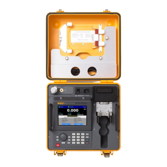
Product Overview The Fluke 4322 Automated Pressure Calibrator (the Product or Calibrator) is a transportable system including an automated controller for calibration and testing of pressure measurement instruments (see Figure 1-1). The Calibrator can be used to calibrate and test analog gauges, digital gauges, pressure transducers, pressure switches, and other pressure devices. -
Page 14: Safety Information
Do not dispose of this product as Conforms to European Union unsorted municipal waste. Go to directives Fluke’s website for recycling information. Risk of Danger. Important Hazardous voltage information. See manual. -
Page 15: The Product Manual Set
This 4322 Operators Manual contains basic system and feature information, operation instructions, and basic user maintenance and troubleshooting information. • The 4322 Service Manual contains service, calibration, and repair information and instructions. Contact Fluke Calibration To contact Fluke, call one of the following telephone numbers: •... -
Page 16: Calibration And Repair Information
Calibration and Repair Information To schedule and send the Calibrator to Fluke for calibration or repair: 1. Contact the Fluke Calibration Service Center in your area to schedule the calibration or repair (see Table 1-2). 2. Pack and secure the Calibrator in a shipment box with a minimum of 2 inches of packing around the Calibrator to prevent damage. -
Page 17: Controller Indicators And Controls
Product Overview and Specifications Controller Indicators and Controls Controller Indicators and Controls The Pressure Controller (the Controller) shown in Table 1-3, is an electronic pressure controller that precisely sets, controls, and measures pressure. Table 1-3 shows the items on the front panel along with a brief description. Table 1-3. - Page 18 USB 2.0 USB printer interface used to print test calibration reports (see “Print a Test Report” in Chapter 3. Printer Note The printer must be PCL-5 compatible. GPIB IEEE-488.2 remote operation interface. See Chapter 5, “Remote Operation”. RS-232 Port Used by Fluke Calibration for diagnostic testing. ...
- Page 19 Product Overview and Specifications Controller Indicators and Controls The control panel has 23 keys and a dual-purpose, push button/rotary dial to navigate and control the user interface. After a test is started, the keys are used to control and adjust the parameters of the test in progress.
- Page 20 4322 Operators Manual Table 1-4. Control-Panel Keys and Functions (cont.) Key Function: Menu Navigation Item Key Function: Test in Progress and Test Configuration Increases or decreases applied pressure. Cycles through the on-screen The longer a key is pushed, the faster the ...
-
Page 21: Handheld Control Indicators And Controls
Product Overview and Specifications Handheld Control Indicators and Controls Handheld Control Indicators and Controls The Handheld Control (the Handheld) has seven keys and a dual-purpose, push button/rotary dial to navigate and control the user interface (see Table 1-5). The Handheld has a display that shows information such as test settings and pressure settings. The keys on the Handheld allow for direct test control of the test in progress. - Page 22 4322 Operators Manual Table 1-5. Handheld Control Keys and Functions (cont.) Key Function: Menu Item Navigation and Test Key Function: Test in Progress Configuration Opens the selected menu or set the Select selected value in the highlighted field. Aborts (stops) the test and quickly vents the ...
-
Page 23: Pressure Intensifier Indicators And Controls
Product Overview and Specifications Pressure Intensifier Indicators and Controls Pressure Intensifier Indicators and Controls The Pressure Intensifier (the Intensifier) shown in Table 1-6 is an electric pressure booster system that can boost gas pressure supply from (500 to 3,000) psig up to 10,000 psig. - Page 24 4322 Operators Manual Table 1-6. Intensifier Controls and Indicators (cont.) Item Name Function Spring-Loaded Case Spring-loaded latches used to keep the lid closed and sealed. Latches Keypad used to select the Intensifier pressure. Keypad selections Intensifier Pressure are in 1,000 psig increments that range from 1,000 psig to 10,000 Selection Keys ...
-
Page 25: Accessory Kit Items
Adaptors Kit, and Table 1-9 is a list of additional seals, filters, and fuses in the Spares Kit. To order replacement parts or additional accessories, contact Fluke Calibration and reference the part numbers listed in the “List of Replacement Parts” section in the 4322 Service Manual. Table 1-7. Accessories gxj034.eps... - Page 26 Regulator. DMM Holder Foam cutout for a Fluke Digital Multimeter. CD that contains the 4322 Operators Manual and 4322 Service Manuals CD Manual. Nitrogen Cylinder Pressure regulator that lets you turn on and turn off pressure and ...
- Page 27 Product Overview and Specifications Accessory Kit Items Table 1-8. Accessories - Adaptor Kit NPT M NPT F gxj035.eps Item Name Function FITTING, 1/2 MALE PIPE THREAD (NPT) Quick-connect adapter. Each adaptor is marked with its maximum working pressure. FITTING, 1/4 MALE PIPE THREAD (NPT) ...
-
Page 28: Specifications
O-RING,CAST URETHANE,90 DURO,003 (0.060 W X 0.056 ID) O-RING,VITON,2-002,3/64 ID,9/64 OD,3/64 W,DURO 90,BLACK SEAL ASSEMBLY, HIGH PRESSURE,T61 SEAL /P02 BACKUP RING /FKM O-RING O-RING,VITON,1MM W X 3.5MM ID,90 DURO,BLACK 4322-5772,DECAL, SPARE PARTS CASE CASE,ABS,3.875INX2.375INX1.375IN,WITH HANDLE,BLACK FUSE,5A,250VAC,TIME LAG,5X20MM,CERAMIC 4322-5933,CUT DETAIL, COALESCING FILTERS... -
Page 29: Pressure Limits
Nitrogen Cylinder Regulator Outlet Miniature QC female 20 MPa (3,000 psi) Note: IQC70 is a Fluke Calibration interlocking quick connection nominally rated to 70 MPa (10,000 psi). Accessory Kit Fittings Maximum Working Name Type of Fittings Pressure Limit Fitting, 1/2 Male Pipe Thread (NPT) -
Page 30: Measurement Specifications
QC at the other. Notes: IQC70 is a Fluke Calibration interlocking quick connection nominally rated to 70 MPa (10,000 psi). Hose limited to 3,000 psi due to miniature QC used to connect to the fitting on the regulator. Measurement Specifications Barometer Module Range ........ -
Page 31: Pressure Switch Testing Specifications (Handheld)
Product Overview and Specifications Specifications Typical Control Set Times Measure Mode Range Time (seconds) [1] [6] <28 kPa (4 psi) gauge 28 kPa to 700 kPa (4 to 100 psi) gauge Gauge 700 kPa (100 psi) gauge to 7 MPa (1,000 psi) gauge 7 MPa (1,000 psi) gauge to 70 MPa (10,000 psi) gauge [1] [6] <14 kPa (2 psi) absolute... - Page 32 4322 Operators Manual 1-22...
-
Page 33: Setup
Chapter 2 Setup Title Page Introduction ......................2-3 Quick-Connector Fittings .................. 2-3 Configure the Pressure Supply ................2-4 Controller Only ....................2-4 Controller and Nitrogen Cylinder ..............2-5 Controller and Intensifier ................2-5 Internal and External Supply Setting ............. 2-6 Contamination Prevention ................. - Page 34 4322 Operators Manual...
-
Page 35: Introduction
The QC is locked when pressure is applied. Each QC fitting contains a small, in-line filter to prevent system contamination. The filters are replaceable and can be replaced by qualified service personnel, see the 4322 Service Manual for instructions on how to replace the filters. -
Page 36: Configure The Pressure Supply
4322 Operators Manual Configure the Pressure Supply The Calibrator has three configurations to maximize portability as shown in Figure 2-2. Read the subsequent sections from more information on each configuration along with instructions on how to set up the Calibrator for the configuration. -
Page 37: Controller And Nitrogen Cylinder
Setup Configure the Pressure Supply Controller and Nitrogen Cylinder The Controller and Nitrogen Cylinder configuration provides maximum portability when the pressure necessary to calibrate the UUT is between 306 psig and 2,000 psig. Note The Controller cannot boost supply pressure from the Nitrogen Cylinder. The pressure available to the UUT is equal to the supply pressure in the Nitrogen Cylinder. -
Page 38: Internal And External Supply Setting
4322 Operators Manual b. Connect the male end of the regulator hose to the Nitrogen Cylinder regulator port. c. Connect the female end of the regulator hose to the male SUPPLY QC port on the Intensifier. See “Quick Connector Fittings” on page 2-3. - Page 39 Setup Configure the Pressure Supply Automatic Pressure Supply Selection Example Test Point 4 (720 psig) At 305 psig, External Supply Controller Switches (Intensifier or Nitrogen to External Source Test Point 5 Cylinder) (480 psig) Test Point 3 (480 psig) Test Point 6 (240 psig) Internal Supply Test Point 2...
-
Page 40: Contamination Prevention
4322 Operators Manual Contamination Prevention To prevent damage to the Controller from contaminates that can be in the UUT and hoses such as water, dirt, oil and grease, the Controller is equipped with a Contamination Protection System (CPS). The CPS consists of an electronically controlled vent, a male and female QC fitting, a filter, and a purge port with a 60 ml plastic waste container (see Figure 2-5). -
Page 41: Install The Cps
Setup Contamination Prevention Blue Orange gxj007.eps Figure 2-6. CPS Configurations Install the CPS 1. Choose a blue or orange marked CPS to use. 2. Unscrew the bottom CPS access cover and check to make sure the coalescing filters are installed and tight. Reinstall the CPS access cover when finished. 3. -
Page 42: Remove The Cps
4322 Operators Manual Remove the CPS 1. Push on the Controller to relieve pressure on the CPS and QC fittings. 2. Purge the test hose (see “Hose Purge” in Chapter 3). 3. Disconnect the test hose from the TEST port. -
Page 43: Connect To A Unit Under Test (Uut)
Setup Connect to a Unit Under Test (UUT) Handheld Control Push into Terminal to Connect Pull on Locking Collar to Disconnect Controller gxj057.eps Figure 2-8. Handheld Control Connection Disconnect the Handheld as follows: 1. Remove the cord from the Controller and the Handheld Control. Pull back the collar on the connector to disengage the collar lock. - Page 44 4322 Operators Manual Caution To prevent damage to the UUT, make sure to select the correct size adapter fitting with the correct thread type. Ensure that all hardware used is rated to adequate working pressure, and that all equipment is in proper working order (for example, no cracks or stripped threads).
- Page 45 Setup Connect to a Unit Under Test (UUT) Caution To prevent damage to a UUT, do not over tighten the QC fitting. If a leak is located between the QC fitting and UUT, make sure the correct adapter is used. Additional Steps For Pressure Switches Only: 10.
-
Page 46: Make A Head-Height Correction
4322 Operators Manual Make a Head-Height Correction For calibration of a UUT at a different height than the Controller, it is necessary to make a head-height correction. The head-height correction is the vertical difference between the reference plane of the UUT to the top of the Test port on the Controller in inches or centimeters. -
Page 47: Controller Settings
Setup Controller Settings gxj067.eps Figure 2-12. Head Menu Controller Settings The Settings Menu The Settings menu screen supplies quick access to the six setting submenus (Table 2-1). The submenus are referred to as “tabs” such as “the Preferences tab” or “the Pressure tab”. - Page 48 4322 Operators Manual Table 2-1. Settings Menu gxj015.eps Item Function Contains basic pressure settings. Pressure Pressure Unit – Set the unit of measure. See “Unit of Measure” in Chapter 3 for a list of units available. Additional custom pressure units can be made.
- Page 49 Setup Controller Settings Table 2-1. Settings Menu (cont.) Item Function Contains general system preferences. Preferences Screen Saver – Set when and what type of screen saver to display. Sound – Set the system sound to Off, Low, Medium, or High. See “Sounds and Alarm Volume”...
- Page 50 Contains Controller calibration settings and information. Calibration View/Edit Calibration – View or edit the calibration coefficients. See the 4322 Service Manual for calibration information and procedures. Run Calibration – Opens a Calibration menu with tools to calibrate the Controller. See Chapter 7 or the 4322 Service Manual for calibration information and procedures.
- Page 51 Setup Controller Settings Table 2-1. Settings Menu (cont.) Item Function Contains maintenance settings. Names – The Controller has a UUT library that can store the names of commonly Internal used UUT names and UUT manufacturers. This feature allows UUTs to be quickly loaded into tests when tests are configured.
-
Page 52: Security Levels
4322 Operators Manual Security Levels The Controller is equipped with three user-level access security levels (Off, Low, and High) to protect from undesired changes to the settings (see Table 2-2). The Controller comes from the factory with the security level set at Low. A Low level restriction is recommended for normal day-to-day operations. -
Page 53: Sounds And Alarm Volume
Setup Controller Settings Change the security level as follows: 1. From the Main menu, select to open the settings menu. 2. Select the tab. Preferences 3. Select a security level. 4. Select to save and close the menu. Sounds and Alarm Volume The Controller uses different sounds to audibly notify the user of actions on the Controller (see Table 2-4). - Page 54 4322 Operators Manual gxj066.eps Figure 2-13. Sound Menu 2-22...
-
Page 55: Controller Operation
Chapter 3 Controller Operation Title Page Introduction ......................3-3 Turn On the Controller ..................3-3 Operating Modes ....................3-3 Warm-up ......................3-3 Common Navigation Buttons ................3-4 The Main Menu ....................3-4 Set and Control Pressure ..................3-6 Set Target Pressure ..................3-8 Interrupt Pressure Control ................ - Page 56 4322 Operators Manual Edit a Test ....................3-29 Copy a Test ....................3-29 Delete a Test ....................3-29 Make a New Gauge/Transducer Test ............3-30 Make a New Pressure Switch Test ............3-33 Run a Test Sequence ..................3-35 View Test Results ....................3-37...
-
Page 57: Introduction
Controller Operation Introduction Introduction This chapter contains instructions on how to operate the Controller. Turn On the Controller To turn on the Controller, connect the mains power cord and push the toggle the switch to the (I) position. The system initializes and a system startup screen shows the model number, serial number, and firmware version. -
Page 58: Common Navigation Buttons
4322 Operators Manual Common Navigation Buttons To navigate the menus, use the on-screen navigation buttons on the bottom of each menu. See Table 3-1 for information and a list of the common navigation buttons found on most menus. To move around the menus, use the Dual-Purpose Push Button/Rotary Dial or the ... - Page 59 Controller Operation The Main Menu Table 3-2. Main Menu (cont.) Item Name Function Shows when the pressure is stable and ready for a measurement. The indications are: (Green) Ready, (Yellow) Near Ready, (Red) Not Ready. Measurement This area also shows important notifications such as the warm-up Indicator countdown and also the Cal Check indicator if there is an issue with a ...
-
Page 60: Set And Control Pressure
“CalCheck Function” on page 3-16). Each pressure module is calibrated individually against an external reference. See the calibration procedure in Chapter 7 or in the 4322 Service Manual for calibration instructions. Use the information in the subsequent sections to set pressure, define limits, and perform pressure functions. - Page 61 Controller Operation Set and Control Pressure Pressure Transducer Modules (Pressure Modules) Barometer Module gxj079.eps Figure 3-2. Pressure Transducer Modules and Barometer Removal...
-
Page 62: Set Target Pressure
4322 Operators Manual Set Target Pressure Target pressure is the numerical pressure value the Controller controls pressure to when commanded. When a target pressure is set, the Controller opens the internal pressure valves and applies pressure to the UUT. As the pressure approaches the target value, pressure control slows to prevent an overshoot. -
Page 63: Dynamic Control Mode
Controller Operation Set and Control Pressure target pressure is set on the Main menu, the Controller uses the control parameters found in the control settings menu in the settings. If a test is run, the Controller uses the control parameters selected and saved in the test setup. The two modes have similar control parameters but control pressure differently (see “Pressure Control Parameters, limits, and Functions”). -
Page 64: Dynamic Control Mode With Jog Approach
Point” calibration, and is useful for calibration of analog dial gauges. The 4322 has more resolution than the UUT and allows the set point to be adjusted up or down so that the UUT pressure gauge needle is aligned on top of a cardinal mark. This •... -
Page 65: Static Control Mode
Controller Operation Set and Control Pressure Dynamic with Jog Approach Pressure Control Set Test Point Pressure Upper Hold Limit Target Pressure Lower Hold Limit Time Coarse Jog Fine Jog Target Pressure Stabilizes UUT Shows the Selected Selected Pressure at Target Pressure. Pressure (Coarse is 1 % (Fine is 0.05 %... -
Page 66: Set The Pressure Limits And Control Limits
4322 Operators Manual Set the Pressure Limits and Control Limits Pressure control limits are user configurable settings the Controller uses to make sure that applied pressure does not exceed the operator defined limitations. Control parameters are configured in the settings menu and also in the test menu. -
Page 67: Control Limits (Hold And Stability)
Controller Operation Set and Control Pressure Control Limits (Hold and Stability) The control hold limit is a symmetrical positive and negative range of pressure above (upper limit) and below (lower limit) the target pressure (see Figures 3-5, 3-6, and 3-8). The Controller does not let the applied pressure go outside the hold-limit range. -
Page 68: Pressure Control Functions
4322 Operators Manual Change the Control Limits as follows (see Figure 3-10): 1. From the Main menu, select to open the settings menu. 2. Select the tab. Control 3. Select to open the control limits menu. Control Limits 4. Set the . -
Page 69: Vent The Controller
Controller Operation Set and Control Pressure Table 3-5. Jog Step Parameters Control Mode Value in Settings Value in Test The default Fine Jog Step value is 0.05 % of target pressure Current value in value. This percentage can be changed in the settings menu. settings or 5 % of the UUT tolerance Example: A Fine Jog Step for a target value of 6,000 psi is 3 psi... -
Page 70: Measurement Settings And Limits
4322 Operators Manual Note When a Test Sequence is run, the Controller automatically vents excess pressure to protect the UUT whenever pressure greater than 110 % of the UUT full scale range is sensed. No manual setting of upper limit or other settings is necessary to engage this protection. - Page 71 Controller Operation Measurement Settings and Limits and seamlessly during every vent operation after the Controller has determined that pressure measurement is fully vented and stable. • Gauge pressure measurement with intrinsically gauge pressure modules (G700K, G10M, G70M): AutoZero tares the reading to zero gauge pressure at vent. •...
-
Page 72: Measurement Indicator
4322 Operators Manual Measurement Indicator The Measurement indicator (also known as the “Ready indicator” in previous products) is a visual indicator that shows when the pressure is stable enough to make an accurate measurement. See Table 3-6 for a list of Measurement Indicators and their definition. For... -
Page 73: Measurement Resolution
Controller Operation Measurement Settings and Limits Note The Controller displays vacuum pressures as negative values (for example, -9.32 psig). Some vacuum gauges do not show a negative sign (-) in front of the reading because they are used for only vacuum measurements (the vacuum gauge would show “9.32 psi vacuum”... -
Page 74: Unit Of Measure
4322 Operators Manual Change the Measurement Resolution as follows (see Figure 3-12): 1. Select the from the Main menu. Measurement Indicator 2. Select 1.0, 0.1, 0.01, 0.001. --or-- 1. Select on the Main menu. 2. Select the tab. Pressure 3. - Page 75 Controller Operation Measurement Settings and Limits Change the Unit of Measure as follows (see Figure 3-13): Note If the Controller does not have a unit that the calibration requires, a custom measurement unit can be made. The custom unit is referred to as a “User Unit”.
-
Page 76: Uut Tolerance Limit
4322 Operators Manual 5. Enter the Units/Pa UUT Tolerance Limit The UUT tolerance limit is the maximum anticipated deviation between the reading of the UUT and the measurement made by the Calibrator. After a test is complete, the Controller compares the UUT Tolerance limit against the actual test results. From the comparison, the Calibration report shows if a UUT passed or failed. -
Page 77: Hose Purge
Controller Operation Controller Tools 6. Select . The Controller will automatically perform the number of system purge cycles specified. Note A System Purge draws contaminants out of the UUT. During this process, some of the contaminant can remain in the test hose. It is recommended to perform an additional Hose Purge after System Purge if such contamination is suspected. -
Page 78: Leak Test
4322 Operators Manual gxj028.eps Figure 3-14. Hose Purge Configuration Leak Test Leak Test is a function of the Controller that checks the Controller and UUT connection for pressure leaks. To detect leaks, the Controller generates pressure and monitors the rate of pressure change over a time period. The total change in pressure (dP) and average rate of change is shown on the Leak Test menu and stays on the menu until the test is reaccomplished. -
Page 79: Exercise
Controller Operation Controller Tools 5. Navigate to and select to start the leak test. 6. If the leak rates are excessive, search for a leak path around the adapter fittings first. To search for leaks, use a spray bottle with a mixture of water and diluted soap to spray on the fittings. -
Page 80: Test A Uut
4322 Operators Manual 4. Navigate to and select on the bottom of the Main menu. An Exercise menu appears. 5. Configure the test as follows: a. Set the number of times to exercise the UUT in the field. Cycles b. -
Page 81: The Test Menu
Controller Operation Test a UUT The Test Menu The Test menu allows for quick access to run a test, edit a test, or make a new test (see Table 3-10). Each UUT type selection has different test options and settings that show on the menu. -
Page 82: Test Sequences
4322 Operators Manual Test Sequences A Test Sequence is a test file that is configured by the user and saved to Controller memory. These test files can be created, edited, saved, and deleted. Each test file contains test settings and parameters that the Controller uses when the test is run. After the test is run, the user uses the on-screen prompts to complete the test. -
Page 83: Find A Saved Test
Controller Operation Test a UUT Find a Saved Test To find and load a saved test: 1. From the Main menu, select to open the test menu. 2. Choose , or Pressure Gauge Compound Gauge Pressure Switch Transducer from the UUT Type drop-down box. 3. -
Page 84: Make A New Gauge/Transducer Test
4322 Operators Manual Make a New Gauge/Transducer Test Create a new pressure gauge, compound gauge, or transducer test as follows: Note The Gauge/Transducer New Test menu looks different and contains different Test Settings than the Pressure Switch new test menu. Figure 3-17 shows the two menus. - Page 85 Controller Operation Test a UUT a. Select a pressure unit from the drop-down box. Unit b. Select a measurement mode from the drop-down box. Mode c. Key in the full scale limit of the UUT in the field. Full Scale d.
- Page 86 4322 Operators Manual Table 3-11. Edit Test Menu (cont.) Item Name/Button Function Sequence Shows the number and target value of each test point. Window Add a test point to the test. Add a vent to atmosphere test point. An ATM test point vents all pressure to atmosphere to allow the user to make a vented atmosphere measurement.
-
Page 87: Make A New Pressure Switch Test
Controller Operation Test a UUT 7. Change the test name (if required). 8. Push to save the test and exit to the Main test menu. The new test is loaded and is now shown on the Main test menu. 9. - Page 88 4322 Operators Manual a. Select and key in the High up scale limit pressure value. b. Select and key in the Low up scale limit pressure value. c. Select and key in the High down scale limit pressure value. d. Select and key in the Low down scale limit pressure value.
-
Page 89: Run A Test Sequence
Controller Operation Test a UUT Run a Test Sequence A Test Sequence lets the user fully configure and run a test to calibrate a UUT. After a Test Sequence is complete, the results can be printed to a test report. See “Test Files” for instructions on how to make a new test, edit a saved test, and manage saved tests. - Page 90 4322 Operators Manual 10. Run the test as follows: a. On the run test menu, select to run the test when ready. The Controller controls pressure to the first target pressure test point and controls the pressure with the set control mode set in the test settings.
-
Page 91: View Test Results
Controller Operation View Test Results View Test Results After a test is complete, the test results can be viewed on the Test Results menu. The Test Results menu shows each test point, target pressure, deviation pressure, deviation percentage, and whether the UUT passed or failed the test point. To determine the pass or fail criteria, the Controller compares the reference value (the Controller) to the UUT value (UUT reading). -
Page 92: Print A Test Report
4322 Operators Manual View Past Results as follows: 1. Select on the Main menu to open the Run Test menu. 2. Select a UUT type from the UUT Type drop-down box. 3. Select a test from the Test drop-down box (see “Find a Saved Test” on page 3-29). -
Page 93: Intensifier Operation
Chapter 4 Intensifier Operation Title Page Introduction ......................4-3 Turn On the Intensifier ..................4-3 Choose a Boost Pressure ..................4-3 Set Boost Pressure ..................... 4-4 Vent the System ....................4-5 Isolate Pressure ....................4-5... - Page 94 4322 Operators Manual...
-
Page 95: Introduction
Intensifier Operation Introduction Introduction This chapter supplies boost pressure information and instructions on how to set the boost pressure on the Intensifier. Turn On the Intensifier To turn on the Intensifier, connect the mains power cord and toggle the power switch to the (I) position. -
Page 96: Set Boost Pressure
4322 Operators Manual Boost pressure selection is dependent on the pressure necessary to complete the UUT calibration. For a typical UUT calibration, select an intensifier pressure equal to or greater than the maximum pressure necessary to complete the calibration. Note The Intensifier boost pressure is typically 5% to 8 % higher than the set pressure requested. -
Page 97: Vent The System
Intensifier Operation Vent the System Vent the System Vent the Intensifier as follows: 1. Push to turn off pressure generation. 2. Turn off the Nitrogen Cylinder Regulator. 3. Turn the Vent Valve counterclockwise to vent the pressure. Caution To prevent damage to the knob, do not force the knob after it reaches the full open or closed position. - Page 98 4322 Operators Manual...
-
Page 99: Remote Operation
Chapter 5 Remote Operation Title Page Introduction ......................5-3 USB Remote Interface Setup ................. 5-4 IEEE-488 (GPIB 488.2) Remote Interface Setup .......... 5-4 Remote Operation Commands ................5-4 Overview of Command Structures ..............5-4 Alphabetical List of Remote Commands ............5-5 Remote Command Format ................ - Page 100 4322 Operators Manual...
-
Page 101: Introduction
(1 to 31) uses to identify it from other possible devices connected to the PC. The default GPIB address for the 4322 is “10”. The IEEE-488 port can also be used to communicate with an external pressure reference for the self-calibration function. -
Page 102: Usb Remote Interface Setup
To use the USB interface for remote operation, a driver needs to be installed on the computer. The driver is included in Windows but you must use the identification file on the CD that came with the 4322 to enable the Windows driver. If the CD becomes lost, go to the Fluke website at www.flukecal.com... -
Page 103: Alphabetical List Of Remote Commands
Read the Standard Event Status Register. *IDN? Read the identification information. *OPT? Read the optional hardware that is installed. *RST Reset the 4322 to a known state. *SRE[?] Read or set the Service Request Enable Register. *STB? Read the Status Byte Register. CALx:PRES:DATA[?] [data,,] Read or set the user calibration coefficients. - Page 104 SYST:BEEP:IMM Beep the system beeper. SYST:VER:LOGIC? Read the programmable logic versions. SYST:COMM:GPIB:SELF:ADDR[?] [addr] Read or set the 4322 device GPIB address. SYST:DATE[?] [yyyy,mm,dd] Read or set the System Date. SYST:ERR? Read the most resent error from the error queue. SYST:HOUR?
-
Page 105: Remote Command Format
Remote Operation Remote Operation Commands Table 5-2, List of Alphabetical Commands (cont.) Command Quick Description SYST:TIME[?] [hh,mm,ss] Read or set the System Time. SYST:TIM:COUN[?] Get the elapsed seconds since power up SYST[x]:VER:THM? Read a sensor’s firmware version. UNIT:PRESsure[?] [unit] Read or set the pressure units UNIT:LENG[?] [unit] Read or set the head height units UNIT:TEMP[?] [n]... -
Page 106: Common And Status Commands
Operators Manual Common and Status Commands The 4322 supports a set of commands that are common to all instruments that conforms to the IEEE standard 488.2. In this section, each of these common and status commands are described and contains an example for reference. -
Page 107: Specific Commands
Remote Operation Remote Operation Commands Example: * RSR? Response: *SRE[?] Read or set the Service Request Enable Register (see “488.2 Status System” on page 5-17). Example: *SRE? Response: Set Example: *SRE 28 *STB? Read the Standard Event Status Register (see “488.2 Status System” on page 5-17). Example: STB? Response:... - Page 108 4322 Operators Manual CALx:PRES:DATE[?] [yyyy,mm,dd] or CALIBRATEx:PRESSURE:DATE[?] [yyyy,mm,dd] Read or set the user calibration date for the specified sensor. The entered values are all numeric and “yyyy” is a four digit year (2000-2135). The default value is 2000. “mm” is a two digit month (1-12), and “dd”...
- Page 109 Remote Operation Remote Operation Commands CALC:LIM:UPP[?] [limit] or CALCULATE:LIMIT:UPPER[?] [limit] Read or set the upper limit for set-points in the current displayed pressure units after they are requested. Pressure generation will abort and an alarm will sound if the pressure is above this limit.
- Page 110 4322 Operators Manual MEAS:PRES:SLEW? or MEASURE:PRESsure:SLEW? Reads the slew rate for the active sensor. The response is sent in the current pressure measurement unit per second when the next measurement is available. Example: MEAS:PRES:SLEW? Response: 0.28 MEAS[x]:ZERO:VAL[?] [P ] or MEASURE[x]:ZERO:VALUE[?] [P Read or set the zero values for the three measurement elements (A, B, and C) within the specified sensor.
- Page 111 Remote Operation Remote Operation Commands SENS:PRES:RES[?] [res] or SENSE:PRESSURE:RESOLUTION[?] [res] Read or set the pressure resolution with res in % of reading as indicated on the front panel. Range = {1.0000 - 0.0001 %} Read Example: SENS:PRES:RES? Response: 0.0100 Set Example: SENS:PRES:RES 0.001 SENS:PRES:MODE[?] [mode] or SENSE:PRESSURE:MODE[?] [mode] Read or set the pressure measurement mode where ‘mode’...
- Page 112 This happens only if targ is within acceptable limits of the currently active sensor. A targ value of '0' will vent the 4322 when in gauge mode. Use the RDY and NRDY flags of the “RSR” register using the...
- Page 113 Remote Operation Remote Operation Commands Operation Summary bit of the Status register to be set when changes in the specific events occur. (see “488.2 Status System” on page 5-17). Read Example: STAT:OPER:ENAB? Response: Set Example: STAT:OPER:ENAB 10 STAT:OPER:EVEN? or STATUS:OPERATION:EVENT? Read changes in the operation register (see “488.2 Status System”...
- Page 114 4322 Operators Manual SYST:KLOC[?] [0|1] or SYST:KLOCK[?] [0|1] Locks or unlocks the system keypad (except for the ABORT key). The keypad is always unlocked when the Controller is powered up. ‘n’ = 0/1 for unlock/lock. Read Example: SYST:KLOCK? Response: Set Example:...
-
Page 115: 488.2 Status System
Remote Operation 488.2 Status System 488.2 Status System The Status System lets the operator monitor various Controller operating conditions. 8 bit or 16 bit registers are used to access the conditions, where each individual bit serves a specific function. Masks can be set up to enable the desired conditions to be checked, or all conditions can be read and deciphered as needed. - Page 116 4322 Operators Manual The Status Byte Register can be read using the “*STB?” query, or by performing a serial poll on the GPIB488 interface. If read with a serial poll, then Bit 6 is the RQS. If the “∗STB?” query is used, then bit 6 is the MSS bit. All of the other bits are common to both types of query.
-
Page 117: Standard Event Register
Remote Operation 488.2 Status System Standard Event Register The Controller contains a 8 bit Standard event register (ESR) that reflects specific events. Enabled events in this register will set or clear the ESB bit of the Status Byte Register. Bit 7 (128) Bit 6 (64) Bit 5 (32) Bit 4 (16) -
Page 118: Operation Status Register
4322 Operators Manual Operation Status Register The 16 bit Operation Status Register reflects Controller specific events. Enabled events in this register will set or clear the Operational Event Register Summary Bit of the Status Byte Register Only 2 bits are used while the remaining 14 are reserved for future use:... - Page 119 Remote Operation Remote Errors Table 5-3. Error Values (cont.) Error Code Queue overflow -350 Query error -400 User defined coefficient cannot be 0 Not available with a gauge sensor Not available with an absolute sensor Not available with gauge units Not available with absolute units Pressure exceeds range maximum pressure Numeric data not part of set...
- Page 120 4322 Operators Manual 5-22...
-
Page 121: Operator Maintenance And Troubleshooting
Chapter 6 Operator Maintenance and Troubleshooting Title Page Introduction ......................6-3 Fuse Replacement ....................6-3 Clean the Front Panels and Cases ..............6-5 Controller Identification ..................6-5 Controller Event Log ..................6-5 Reset Controller Settings ................... 6-6 Nitrogen Cylinder Maintenance ................. 6-6 Safety ...................... - Page 122 4322 Operators Manual...
-
Page 123: Introduction
Introduction This chapter contains maintenance tasks that can be performed by the operator such as general care, cleaning, fuse replacement, and Nitrogen Cylinder servicing. See the 4322 Service Manual for maintenance and repair procedures that are to be performed by qualified maintenance personnel. - Page 124 4322 Operators Manual Controller Fuse Holder Intensifier gxj081.eps Figure 6-1. Fuse Replacement...
-
Page 125: Clean The Front Panels And Cases
Operator Maintenance and Troubleshooting Clean the Front Panels and Cases Clean the Front Panels and Cases To clean the Calibrator, wipe it with a cloth that is lightly dampened with water or mild detergent. Do not use aromatic hydrocarbons, chlorinated solvents, or methanol based fluids. -
Page 126: Reset Controller Settings
4322 Operators Manual Reset Controller Settings The Controller has a series of settings reset functions that allows the operators or maintenance personnel reset or clear data from the Controller. Table 6-3 shows the five reset functions available along with a brief description. -
Page 127: Visual Inspection
Operator Maintenance and Troubleshooting Nitrogen Cylinder Maintenance • Do not attempt to modify the threads or force a valve into the Cylinder. • Do not attempt to remove metal from the Cylinder by any means as it will render the cylinder unsuitable for the rated pressure containment. -
Page 128: Internal Cylinder Cleaning Procedure
4322 Operators Manual Internal Cylinder Cleaning Procedure Clean the inside of the Nitrogen Cylinder as follows: Warning To prevent personal injury, keep the threads and inside of the cylinder dry and free from oil, dirt or other contaminants. For oil, grease, and lubricants : Note Complete the process without a break. -
Page 129: Nitrogen Recharge Procedure
Operator Maintenance and Troubleshooting Nitrogen Cylinder Maintenance Nitrogen Recharge Procedure Use the procedure in this section to recharge the Cylinder. It is recommended that each operator write a comprehensive procedure that contains amplified instructions that includes specific steps for their filling apparatus. Warning To prevent injury: •... - Page 130 4322 Operators Manual Nitrogen Cylinder Regulator (supplied) Cylinder Main Shutoff Nitrogen Cylinder Fill Adapter (supplied) Example Fill Regulator (not supplied) Filling Apparatus (both combined) gxj083.eps Figure 6-2. Nitrogen Fill Adapter 6-10...
-
Page 131: Controller Troubleshooting
Operator Maintenance and Troubleshooting Controller Troubleshooting Controller Troubleshooting Use the information in the subsequent sections to troubleshoot the Controller. Controller Fault Codes Code Description Action Number Fault codes 01 and 02 indicates problems with the comm board pca. To clear the fault: IEEE port failure 1. - Page 132 4322 Operators Manual Code Description Action Number [###] pressure transducer Fault codes 41 through 53 indicates problems with the module not responding pressure transducer modules, the barometer modules, or the associated pca assemblies. To clear the fault: [###]pressure transducer 1. Make sure the module is in the correct slot.
-
Page 133: Electrical Problems
Operator Maintenance and Troubleshooting Controller Troubleshooting Electrical Problems Problem Probable Cause Action The Controller does not turn on. Not plugged in. Make sure the unit is plugged in and power is available. If the Power not available. unit is plugged in, use the Fuse blown. -
Page 134: Cps And Quick-Connect Problems
4322 Operators Manual CPS and Quick-Connect Problems Problem Probable Cause Action Cannot remove the CPS from System is pressurized. Vent pressure. Once the CPS is the Controller. removed, clean or repair the Dock interlock not working interlock. correctly. Cannot connect the hose to the Wrong fitting. -
Page 135: Pressure Selection And Led Indications
Operator Maintenance and Troubleshooting Intensifier Troubleshooting Pressure Selection and LED Indications Problem Probable Cause Action STOP key LED flashing slow. Supply pressure is below Increase supply pressure to 500 psi. 500 psi or more. Push to clear the error. When pressure selection is Target pressure key pushed with Increase supply pressure to... -
Page 136: Pressure Generation And Indication Problems
4322 Operators Manual Pressure Generation and Indication Problems Problem Probable Cause Action Pressure generation is slow but Possible worn piston seals. If generation takes more than does build to pressure selection. 4 minutes to reach set pressure or if pressure generation is erratic (above and below set pressure) then replace seals. -
Page 137: Self-Calibration Procedure
Chapter 7 Self-Calibration Procedure Title Page Introduction ......................7-3 Fundamentals ..................... 7-3 Required Equipment ..................7-4 Environmental Conditions ................. 7-4 Equipment Setup ....................7-4 Preliminary Operations ..................7-5 Module Calibration Procedure ................7-7 Module Alignment Procedure ................7-9... - Page 138 4322 Operators Manual...
-
Page 139: Introduction
This chapter does not contain information on the Intensifier because the Intensifier does not require a calibration procedure. If the pressure transducer in the Intensifier needs adjusted, use the adjustment procedure in the 4322 Service Manual. Fundamentals Pressure transducer modules (the modules) are removable and interchangeable without effect on their measurement performance or calibration. -
Page 140: Required Equipment
Fluke 4322 required CPS module (Contamination Clean and dry. Supplied with Fluke 4322 Prevention System) Cylinder hose 10,000 psi, Fluke 4322 QC stem Supplied with Fluke 4322 Intensifier outlet hose 10,000 psi, Fluke 4322 QC stem Supplied with Fluke 4322 Test hose... -
Page 141: Preliminary Operations
Preliminary Operations Prepare for the calibration procedure as follows: 1. Turn on the 4322 Pressure Controller (the Controller) and let it warm up for at least 30 minutes. 2. Turn on the King Nutronics 3689 control unit (KN 3689) and let it warm up for at least 1 hour. - Page 142 4322 Operators Manual b. On the Intensifier, make sure the VENT valve is closed and the ISOLATION valve is full open. c. Fully open the Nitrogen Cylinder regulator to supply pressure to the Intensifier. 5. Put a clean, dry CPS into the Controller.
-
Page 143: Module Calibration Procedure
Adjustment Tol % will be disabled if Use Tol is set to No. c. Use Tol: Yes to use the Adjustment tol % from the last step or No d. Head Relative to 4322: 0 if on the same surface. If not, measure the head-height difference and enter it into the field. - Page 144 4322 Operators Manual hbx070.jpg Figure 7-3. Calibration Menu Configuration 7. Select . This starts the calibration procedure. The Calibration procedure is an automated process. The Controller automatically sets pressure, dwells, and takes measurements. As the test runs, the Controller reads the measurements from the modules and receives measurements data from the KN 3689 over the GPIB connection.
-
Page 145: Module Alignment Procedure
Adjustment Tol % : [user entry] c. Use Tol: Yes to use the Adjustment tol % from the last step or No d. Head Relative to 4322: 0 if on the same surface. If not, measure the head-height difference and enter it into the field. - Page 146 4322 Operators Manual hbx068.jpg Figure 7-5. Alignment Menu Configuration 7. Select . This starts the Alignment procedure. The Alignment procedure is an automated process. The Controller automatically sets pressure, dwells, and takes measurements. As the test runs, the Controller reads the measurements from the modules and receives measurements data from the KN 3689 over the GPIB connection.
Need help?
Do you have a question about the 4322 and is the answer not in the manual?
Questions and answers