
Related Manuals for Allen-Bradley PowerFlex 20-HIM-A6


Summary of Contents for Allen-Bradley PowerFlex 20-HIM-A6
- Page 1 User Manual Original Instructions PowerFlex 20-HIM-A6 and 20-HIM-C6S HIM (Human Interface Module) Firmware Revisions FRN 1.xxx - 2.xxx...
- Page 2 Important User Information Read this document and the documents listed in the additional resources section about installation, configuration, and operation of this equipment before you install, configure, operate, or maintain this product. Users are required to familiarize themselves with installation and wiring instructions in addition to requirements of all applicable codes, laws, and standards.
- Page 3 Summary of Changes This manual contains new and updated information as indicated in the following table. Topic Page Added the PowerFlex® 755T drives to the product compatibility list. Imported a diagram of the PowerFlex 755T-series drive Added a note to the Process Screen section Added a note to the Creating a User-Defined Drive/Peripheral Name section Added a note to the Customizing the Process Screen section Replaced ‘password’...
- Page 4 Summary of Changes Notes: Rockwell Automation Publication 20HIM-UM001E-EN-P - May 2017...
-
Page 5: Table Of Contents
Table of Contents Preface Conventions Used in This Manual ....... . . 9 Rockwell Automation Support . - Page 6 Table of Contents Chapter 4 Using the HIM Initial HIM Operation on New Drive Powerup..... 33 Selecting Display Contrast ........34 Setting the Date/Time for PowerFlex 750-Series Drives .
- Page 7 Table of Contents Appendix A Specifications Communications..........67 Electrical .
- Page 8 Table of Contents Notes: Rockwell Automation Publication 20HIM-UM001E-EN-P - May 2017...
-
Page 9: Conventions Used In This Manual
• Support service agreements Technical Product Assistance For technical assistance, please review the information in Chapter 4, Using the HIM, first. If you still have problems, then access the Allen-Bradley Technical Support website at http://www.ab.com/support/abdrives or contact Rockwell Automation. Rockwell Automation Publication 20HIM-UM001E-EN-P - May 2017... -
Page 10: Additional Resources
Information on installing and programming PowerFlex Digital DC drives. You can view or download publications at http:// literature.rockwellautomation.com. To order paper copies of technical documentation, contact your local Allen-Bradley distributor or Rockwell Automation sales representative. To find your local Rockwell Automation distributor or sales representative, visit http://www.rockwellautomation.com/locations. -
Page 11: Him Types
English, which will always remain as the default language. Features The enhanced PowerFlex 20-HIM-A6 and 20-HIM-C6S HIMs provide the following benefits over the more basic PowerFlex 7-Class HIMs (catalog numbers 20-HIM-A3, 20-HIM-A5, 20-HIM-C3S, and 20-HIM-C5S): •... -
Page 12: Compatible Products
Chapter 1 Getting Started • Support for English, and customary European and Asian languages. • Dynamic soft keys that change functions/names based on screen or data entry mode to reduce keypad keys and simplify HIM operation. • Customizable drive monitoring items that can be displayed as a list on the process screen or as individual screens. -
Page 13: Chapter 2
Chapter Installing the HIM This chapter provides instructions for installing and removing the HIM. Topic Page Installing the 20-HIM-A6 HIM Installing the 20-HIM-C6S HIM Removing the HIM There are two types of enhanced PowerFlex® 7-Class HIM: • NEMA Type 1 (catalog number 20-HIM-A6) •... -
Page 14: Installing The 20-Him-A6 Him
Chapter 2 Installing the HIM Installing the 20-HIM-A6 HIM The 20-HIM-A6 (NEMA Type 1) HIM is normally installed in the HIM bezel (drive Port 1) on the front of the drive. For temporary hand-held operation, the HIM can be plugged into drive Port 2 (near the bottom of the drive control pod for PowerFlex 750-Series drives, or on the bottom of the drive for PowerFlex 7- Class drives) using a 1 m/3.28 ft. - Page 15 Installing the HIM Chapter 2 PowerFlex 750-Series IP54, NEMA/UL Type 12 Drives 1. Unfasten and remove the cover as shown below using the following recommended tools: • Screwdriver: 6.4 mm (0.25 in.) flat or T20 Hexalobular • Hex socket: 7 mm M4 x 0.7 2.
-
Page 16: Using Drive Port 2 Connection For Hand-Held Operation
Chapter 2 Installing the HIM Using Drive Port 2 Connection for Hand-Held Operation PowerFlex 755T-Series Drive Attach a splitter cable to the cradle connector of the HIM. Then plug the other end of the cable into DPI Port 02 near the bottom of the drive control pod. 20-HIM-A6 HIM (PowerFlex 755T drive shown with... -
Page 17: In A Remote-Mount Him Bezel (20-Him-B1)
Installing the HIM Chapter 2 PowerFlex 7-Class Drive Attach a 20-HIM-H10 cable to the bottom of the HIM. Then plug the other end of the cable into Port 2 on the bottom of the drive. (PowerFlex 70 drive shown) 20-HIM-A6 HIM Port 2 20-HIM-H10 Cable (1 m/3.28 ft. -
Page 18: Installing The 20-Him-C6S Him
Chapter 2 Installing the HIM 4. Install the HIM into the remote-mount HIM bezel. PowerFlex 755 drive shown (without HIM in drive HIM bezel) 20-HIM-A6 HIM 20-HIM-B1 Remote-Mount 4 a. Push in. HIM Bezel 4 b. Slide down. 3 m/9.8 ft. long 1202-C30 bezel cable included with 20-HIM-B1 remote-mount HIM bezel. - Page 19 Installing the HIM Chapter 2 Figure 1 - 20-HIM-C6S HIM Dimensions Dimensions are in millimeters and (inches). 93.0 25.0 (3.66) (0.98) 3.0 m/9.8 ft. long 1202-C30 cable (included with 20-HIM-C6S HIM) 180.0 (7.08) 1202-Hxx Extension Cable 1202-H03 = 0.3 m/0.98 ft. long (supplied separately, and only 1202-H10 = 1.0 m/3.28 ft.
- Page 20 Chapter 2 Installing the HIM Figure 2 - Hole Pattern to Mount the 20-HIM-C6S HIM Dimensions are in millimeters and (inches). 67.0 (2.63) 60.0 (2.36) Front View 77.0 (3.03) Ø 19.1 (0.75) (2.32) 77.0 Ø 4.8 (3.03) (0.19) 2. Peel the protective film from the gasketed surface on the back of the HIM. IMPORTANT Adhesive coated gasket is designed for one-time only installation.
-
Page 21: Removing The Him
Installing the HIM Chapter 2 3. Insert the supplied 3 m/9.8 ft. long 1202-C30 HIM cable into the mating socket on the back of the HIM. 4. Install the supplied O-ring into the cable routing hole on the panel to protect the cable. - Page 22 Chapter 2 Installing the HIM Notes: Rockwell Automation Publication 20HIM-UM001E-EN-P - May 2017...
-
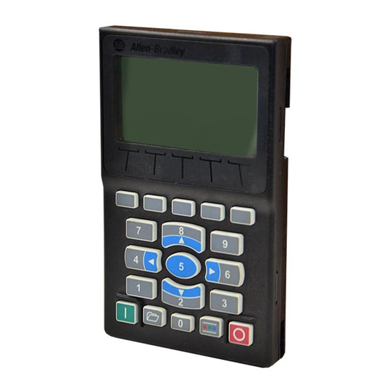
Page 23: Him Keypad
Chapter HIM Components This chapter describes the components of the HIM. Topic Page HIM Keypad LCD Display Elements Main Screens The keypad consists of soft keys, navigation and number keys, and single-function HIM Keypad keys, which are described in their respective subsections that follow. Soft Keys The soft keys on the HIM are located at the top of the keypad and highlighted below. -
Page 24: Navigation And Number Keys
Chapter 3 HIM Components Navigation and Number Keys The five blue multi-function keys (2, 4, 5, 6, and 8) shown below are used to do the following: • Enter their respective numeric value • Scroll menus/screens • Perform corresponding functions displayed in the Data Area (see page Multi-function Key Name... -
Page 25: Single-Function Keys
HIM Components Chapter 3 Single-function Keys There are four single-function keys, which are highlighted below and listed in the table below. Each single-function key always performs only its dedicated function. Single-function Key Name Function Start Starts the drive. Folders Accesses folders for parameters, diagnostics, memory functions, preferences, and other tasks. -
Page 26: Lcd Display Elements
Chapter 3 HIM Components LCD Display Elements The basic HIM screen is divided into three display zones, which are shown in Figure 3 and described in their respective subsections that follow. Figure 3 - HIM Display Zones Stopped AUTO Status Bar 0.00 Hz Host Drive 240V... -
Page 27: Soft Key Labels
HIM Components Chapter 3 Soft Key Labels The Soft Key Labels identify the present function of a corresponding Soft Key on the Key Pad. Different screens may show different Soft Key Labels. VIEW PAR# TEXT Soft Key Labels Soft Keys Soft Key Label Name Function... -
Page 28: Main Screens
Chapter 3 HIM Components Soft Key Label Name Function MOST Most Restores most Host or Port device parameters to factory defaults. PAR# Parameter Number Navigates directly to a parameter. PGDN Page Down Scrolls down to the next page of data lines on the Device Version information screen. PGUP Page Up Scrolls up to the previous page of data lines on the Device Version information screen. -
Page 29: Process Screen
HIM Components Chapter 3 Status Screen Soft Keys Label Name Function Escape Toggles between the Status and Process Display screens. Language Icon Directly accesses the Select Language To Use screen. Reference Enters the speed reference for the Host Drive. PAR# Parameter Number Directly accesses a parameter for the device on selected port. -
Page 30: Control Screen
Chapter 3 HIM Components Process Screen Navigation/Number Keys Name Function Screen Element 8/Up Arrow Scrolls up through the display lines. 2/Down Arrow Scrolls down through the display lines. Control Screen The Control screen (shown below) is used to directly control the drive. It displays vertical bar graphs of the drive’s speed Reference and Feedback values, and a Key Function Map that corresponds to the navigation/number keys for drive control. -
Page 31: Folder Screens
HIM Components Chapter 3 Folder Screens The drive and each connected peripheral has its own set of Folder screens: Folder Screen Description PORTS Displays a list of host drive ports to which peripherals are connected. The host drive is always Port 00. -
Page 32: Fault Display Screen
Chapter 3 HIM Components Fault Display Screen The popup Fault Display screen automatically appears when a fault condition is detected for the host drive or any connected peripheral. The popup Fault Display screen flashes to alert that a fault condition exists. The Fault Display screen (example shown below) provides the following information: •... -
Page 33: Initial Him Operation On New Drive Powerup
Chapter Using the HIM This chapter provides information about using the HIM. Topic Page Initial HIM Operation on New Drive Powerup Selecting Display Contrast Setting the Date/Time for PowerFlex 750-Series Drives Creating a User-Defined Drive/Peripheral Name Customizing the Process Screen Resetting the Drive/Peripherals Setting Factory Defaults Setting Display Flashing for Fault Indication... -
Page 34: Selecting Display Contrast
Chapter 4 Using the HIM Selecting Display Contrast The contrast of the HIM display can be adjusted for optimal viewing. Follow these steps to change the contrast. 1. Access the Status screen, which is displayed on HIM power up. Figure 6 - Status Screen Stopped AUTO 0.00 Hz... -
Page 35: Setting The Date/Time For Powerflex 750-Series Drives
Using the HIM Chapter 4 Setting the Date/Time for The information in this section does not apply to PowerFlex 7- IMPORTANT PowerFlex 750-Series Drives Class drives. The PowerFlex 750-Series drive has a real-time clock which supports its time stamp feature for faults and alarms. This clock must be accurately set to provide meaningful time stamp data. - Page 36 Chapter 4 Using the HIM e. Press the (Enter) key to enter your selected time zone. 9. To set the date: soft key to select the year in the top line. a. Press the b. Use the numeric keys to enter the correct year. To delete an erroneous date (or time) entry, use the soft key.
-
Page 37: Creating A User-Defined Drive/Peripheral Name
Using the HIM Chapter 4 Creating a User-Defined Note: The PowerFlex 755T products do not fully support User Defined text. Drive/Peripheral Name The host drive and each of its connected peripherals has a default name. You can change any of these default names, but each new user-defined name cannot exceed 16 characters in length. -
Page 38: Customizing The Process Screen
Chapter 4 Using the HIM Customizing the Process Note: The PowerFlex 755T products do not fully support Process Display text. Do not use this feature with these products. Screen The Process screen can be displayed as a multi-line or single-line view screen, and can be customized to show different drive monitoring items, apply a scale factor, or change text for the displayed drive parameter. -
Page 39: Changing Displayed Items, Adding A Scale Factor, Or Customizing
Using the HIM Chapter 4 Changing Displayed Items, Adding a Scale Factor, or Customizing Text You can further customize the Process screen by: • Changing a displayed parameter to a different parameter. • Applying a scale factor to the displayed parameter. •... -
Page 40: Resetting The Drive/Peripherals
Chapter 4 Using the HIM Resetting the Drive/ The drive or any of its connected peripherals can be reset by removing and restoring power to the drive (power cycling). If this is not convenient or cannot Peripherals be done because of application circumstances, the HIM can be used to reset the drive/peripherals. -
Page 41: Setting Powerflex 7-Class Drives/Peripherals To Factory Defaults
Using the HIM Chapter 4 7. Use the key to select the appropriate action. • Host and Ports (Preferred): Selects the host device and all ports for a factory default action. • This Port Only: Selects only this port for a factory default action. For a description of a selected menu item, press the INFO soft key. -
Page 42: Setting Display Flashing For Fault Indication
Chapter 4 Using the HIM Setting Display Flashing for Whenever a fault for the host drive or any of its connected peripherals is detected, a popup Fault Display screen (see page 32) appears. By default, only the Fault Indication Status Bar flashes to alert the operator. However, you can change the flash mode for the Fault Display screen to one of the following modes: •... -
Page 43: Setting Display Flashing For Alarm Indication
Using the HIM Chapter 4 Setting Display Flashing for Whenever an alarm for the Host Drive is detected, an alarm bell icon appears in the Status Bar. By default, only the Status Bar flashes to alert the operator. Alarm Indication However, you can change the flash mode for alarm indication to one of the following modes: •... -
Page 44: Viewing/Editing Drive Or Peripheral Parameters
Chapter 4 Using the HIM Viewing/Editing Drive or The PowerFlex 20-HIM-A6 or 20-HIM-C6S HIM can show host drive parameters in a File-Group-Parameter view or by Linear List. To access drive or Peripheral Parameters peripheral parameters for viewing or editing, use either the direct parameter access method or the alternate linear list access method. -
Page 45: Alternate Linear List Access Method
Using the HIM Chapter 4 6. Press the EDIT soft key (for editable parameters only) to display the Edit Parameter popup box. Figure 11 - Example Edit Parameter Popup Box Stopped AUTO 0.00 Hz Edit Accel Time 1 5.0 Secs 0.00 <<... -
Page 46: Viewing/Clearing Drive Faults Or Alarms
Chapter 4 Using the HIM Viewing/Clearing Drive Follow these steps to view/clear drive faults or alarms. Faults or Alarms 1. Access the Status screen (see Figure 2. If Port 00 (host drive) is not shown above the ESC soft key, use the key to scroll to Port 00. -
Page 47: Viewing Peripheral Diagnostic Items
Using the HIM Chapter 4 Viewing Peripheral If you encounter unexpected communication problems, diagnostic items for the drive’s connected peripherals—including the HIM—can help you or Rockwell Diagnostic Items Automation personnel troubleshoot the problem. Follow these steps to view peripheral diagnostic items. 1. -
Page 48: Viewing/Clearing Peripheral Events
To cancel the popup box, press the ESC soft key or select Cancel from the list and press the (Enter) key. The PowerFlex 20-HIM-A6 or 20-HIM-C6S HIM maintains an event queue that reports the history of its actions. Table 2 shows all possible events for the HIM. -
Page 49: Checking Drive And Peripheral Firmware Revisions
Using the HIM Chapter 4 Table 2 - 20-HIM-A6 and 20-HIM-C6S HIM Events Code Event Description Reserved — Device Power Up A normal power up. Device Reset The HIM was reset due to a manual reset command or program crash. EEPROM CRC Error The HIM EEPROM Data Storage Device is corrupt. -
Page 50: Using The Copycat Function
Chapter 4 Using the HIM Using the CopyCat Function PowerFlex 750-Series drives and PowerFlex 7-Class drives provide a CopyCat function that enables you to upload individual parameter sets for the host drive or any of its connected peripherals into the HIM. Furthermore, an Upload All Ports function enables you to conveniently upload multiple parameter sets for the host drive and all of its connected peripherals in one single file. -
Page 51: Renaming Copycat Files
Using the HIM Chapter 4 6. Press the (Enter) key to display the CopyCat Files selection screen. Stopped AUTO 0.00 Hz Port 00 CopyCat Files CopyCat from Device to HIM CopyCat from HIM to Device Delete CopyCat File Rename CopyCat File Before any CopyCat files are created, only the ‘CopyCat From Device to HIM’... - Page 52 Chapter 4 Using the HIM 6. Press the (Enter) key to display the CopyCat Files selection screen. Stopped AUTO 0.00 Hz Port 00 CopyCat Files CopyCat from Device to HIM CopyCat from HIM to Device Delete CopyCat File Rename CopyCat File 7.
-
Page 53: Deleting Copycat Files
Using the HIM Chapter 4 Deleting CopyCat Files 1. Access the Status screen (see Figure 2. Use the key to scroll to the Port of the device whose parameter set you want to delete (for example, Port 00 for the host drive). 3. -
Page 54: Changing Powerflex 750-Series Drive Parameter Associations
Chapter 4 Using the HIM Changing PowerFlex 750- PowerFlex 750-Series drives have special parameters (indirect selector parameters and reference parameters) which are always associated with other parameters. Series Drive Parameter The values for these special parameters are actually pointers to other parameters Associations in the drive or to Host parameters in connected peripherals. - Page 55 Using the HIM Chapter 4 2. Press the EDIT soft key to display the edit popup box for the selected field (in this case, the port number field). Stopped AUTO 0.00 Hz Edit Spd Ref A Sel Select Port To Use Zero Speed Port 00 PowerFlex755 ENTER...
-
Page 56: Using Direct Numeric Entry Method
Chapter 4 Using the HIM association is now changed and the indirect selector or reference parameter screen re-appears with the associated parameter information shown. Stopped AUTO 0.00 Hz Port 00 Dev Param 545 Spd Ref A Sel P0871 Port PowerFlex 755 PAR# EDIT Using Direct Numeric Entry Method... -
Page 57: Linking Parameters In Powerflex 700/700S Drives
Using the HIM Chapter 4 Linking Parameters in Most parameter values are entered directly by the user. However, specific parameters can be ‘linked’ , so the value of one parameter becomes the value of PowerFlex 700/700S Drives another. For example, the value of an analog input can be linked to an acceleration time. -
Page 58: Deleting An Established Link
Chapter 4 Using the HIM Deleting an Established Link Follow these steps to delete an established link. 1. Access the screen for the destination parameter. 2. Press the LINK soft key. 3. In the Link popup box, enter a value of zero. 4. -
Page 59: Using An Access Code
Using the HIM Chapter 4 Using an Access Code All parameter configuration settings for the drive and its connected peripherals can be protected from unauthorized access by using an access code. Setting/Changing the Access Code 1. Access the Status screen (see Figure 2. -
Page 60: Changing Access Code-Protected Drive/Peripheral Parameters
Chapter 4 Using the HIM Changing Access Code-protected Drive/Peripheral Parameters When the host drive is access code-protected, parameter settings for the drive and its connected peripherals can be viewed—but not changed until after the correct access code value is entered. When attempting to edit a parameter value while logged out, the HIM will prompt you for the access code before allowing access. -
Page 61: Disabling Access Code Protection
Using the HIM Chapter 4 Disabling Access Code Protection 1. Access the Status screen (see Figure 2. If Port 00 (host drive) is not shown above the ESC soft key, use the key to scroll to Port 00. 3. Press the key to display its last-viewed folder. -
Page 62: Initiating Powerflex 750-Series Drive Port Verification
Chapter 4 Using the HIM Initiating PowerFlex 750- The information in this section does not apply to PowerFlex 7- IMPORTANT Series Drive Port Verification Class drives. Upon powerup, the HIM verifies that the PowerFlex 750-Series drive has initiated Port Verification. The host drive then checks for port conflicts. If any conflicts are present, a Device Conflicts popup box appears listing all devices with conflicts. -
Page 63: Resolving 'Changed' Or 'Requires Configuration' Conflicts
Using the HIM Chapter 4 Resolving ‘Changed’ or ‘Requires Configuration’ Conflicts When a ‘Changed’ or ‘Requires Configuration’ conflict exists on powerup, a ‘!’ symbol precedes the port number in the Device Conflicts popup box. Stopped AUTO 0.00 Hz Device Conflicts: ! Port 04: Encoder ! Port 05: I/O Module 24 V ! Port 06: Device Not Found... -
Page 64: Changing Language For The Display Text
Chapter 4 Using the HIM Stopped AUTO 0.00 Hz X05: Not Functioning This device must be removed or replaced. Prev: Encoder ENTER 2. Follow the screen prompts to resolve the port conflict. Or press the ENTER soft key to affirm and re-display the Device Conflicts popup box. -
Page 65: Updating The Him Firmware Or Language
When updating firmware through a direct serial connection from the drive to the computer, you can use the same Allen-Bradley software tools described above, or you can use HyperTerminal software set to the X-modem protocol. To obtain a firmware or language update for the HIM, go to http:// www.ab.com/support/abdrives/webupdate. -
Page 66: Rockwell Automation Publication 20Him-Um001E-En-P - May
Chapter 4 Using the HIM Notes: Rockwell Automation Publication 20HIM-UM001E-EN-P - May 2017... -
Page 67: Communications
Appendix Specifications This appendix provides the specifications for the HIM. Topic Page Communications Electrical Mechanical Environmental Regulatory Compliance Communications Protocol Drive Peripheral Interface (DPI™) Data Rates 125 Kbps or 500 Kbps Electrical Consumption 140 mA at 12V DC supplied by the Host Drive Mechanical Dimensions 20-HIM-A6... -
Page 68: Regulatory Compliance
Appendix A Specifications Regulatory Compliance Certification Specification UL508C c-UL CAN / CSA C22.2 No. 14-M91 EN50178 and EN61800-3 C-Tick EN61800-3 NOTE: This is a product of category C2 according to IEC 61800-3. In a domestic environment this product may cause radio interference in which case supplementary mitigation measures may be required. -
Page 69: Parameter List
Appendix HIM Parameters This appendix provides information about the HIM parameters. Besides the HIM, the following configuration tools can also be used to monitor or change parameter values of the HIM, drive, and other connected peripherals: • Connected Components Workbench™ software, version 1.02 or later •... - Page 70 Appendix B HIM Parameters Notes: Rockwell Automation Publication 20HIM-UM001E-EN-P - May 2017...
- Page 71 Index accessing parameters HIM (Human Interface Module) alternate linear list method 45 adjusting display contrast 34 direct parameter access method 44 changing PowerFlex 750-Series drive adjusting display contrast 34 parameter associations 54 checking drive/peripheral firmware revisions Alarm Dspy Type parameter 69 alarm/fault queues for the drive 46 compatible products 12 attentions 12...
- Page 72 Index LCD display elements/descriptions 26 User Dspy Enable parameter 69 linear list access method to parameters 45 User Dspy Time parameter 69 linking parameters in PowerFlex 700/700S using the CopyCat function 50 drives 57 verification of ports for PowerFlex 750-Series main screens/descriptions 28 drives 62 manual...
- Page 74 Rockwell Automation maintains current product environmental information on its website at http://www.rockwellautomation.com/rockwellautomation/about-us/sustainability-ethics/product-environmental-compliance.page. Allen-Bradley, Connected Components Workbench, ControlFLASH, DeviceLogix, DPI, DriveExecutive, DriveExplorer, PowerFlex, Rockwell Automation, Rockwell Software, and SMC are trademarks of Rockwell Automation, Inc. Trademarks not belonging to Rockwell Automation are property of their respective companies.
Need help?
Do you have a question about the PowerFlex 20-HIM-A6 and is the answer not in the manual?
Questions and answers