
Related Manuals for Allen-Bradley 9 Series


Summary of Contents for Allen-Bradley 9 Series
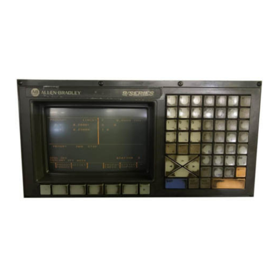
- Page 1 INSTALL GUIDE M L 0 8 0 Q T 8 5 2 0 M S LCD upgrade kit FOR YOUR ALLEN-BRADLEY SERIES 9 (8520MOP) MONOCHROME M20A03-ML080QT8520MS...
-
Page 2: Warranty
IMPORTANT: WARRANTY Before using any MONITECH product please carefully review this Manual as well as any additional documentation provided with your shipment. Attempting any of the following will void product warranty: • unauthorized repairs or parts replacement • inappropriate use or placement: exposing product to liquids, harmful gases, electrical shock, physical shock, temperatures beyond the range of -4°F to 140°F... - Page 3 REMOVAL: Step #1) Turn off turn off main power, turn off machine. Step #2) On the front of your machine, remove the screws holding the HMI in place. Take out the HMI and keep the screws for re-installation. You will have to unplug the video cable and the other cables to take out the HMI.
- Page 4 Step #4) First discharge the CRT, it has high voltage. Be careful. Put a flat head screw driver underneath the anode lead cap so it is touching the metal part. And get another screwdriver and cross it with the flat head used and touch the metal frame with it.
-
Page 5: Installation
Step #6) Now that the CRT is out you are able to remove the driver board by unscrewing the screws holding the board in place. INSTALLATION: Step #7) Put Monitech’s Monitor in the housing using the four screws previously holding the CRT in place. With the screwdriver fasten the 4 screws to... - Page 6 Step #8) Place the CRT Frame with Monitech Monitor assembly back into your HMI by using the screws previously mounting the frame in place. Step #9) Open up your MK068 box, get MAV576 (Adaptor VGA to 15 PIN LD Video Connector. Plug the VGA into the Monitech Monitor and tighten the screws.
- Page 7 Option 2) Cut the jack part of the MAP307 (Power supply) and strip the 2 wires. Solder or use butt connectors to connect the red wire to controller to red wire of jack. Solder or use butt connectors to connect the black wire to controller to black wire of jack.
- Page 8 For Technical Support, Call 1-877-493-6105 Support@Monitech.com 20 Howard Place Kitchener, Ontario N2K 4Z4 CANADA 519.725.222 M20A03-ML080QT8520MS...
Need help?
Do you have a question about the 9 Series and is the answer not in the manual?
Questions and answers