
Related Manuals for Allen-Bradley 2707-M232P3


Summary of Contents for Allen-Bradley 2707-M232P3
- Page 1 DTAM Micro Operator Interface Module Catalog Numbers 2707-M232P3, 2707-M485P3 User Manual...
- Page 2 Since there are many variables and requirements associated with any particular installation, Allen-Bradley does not assume responsibility or liability (to include intellectual property liability) for actual use based upon the examples shown in this publication.
-
Page 3: Table Of Contents
......... 2–8 RS-232 Version (Catalog No. 2707-M232P3) ..... . - Page 4 Table of Contents DTAM Micro Operator Interface Module User Manual Using the Simulate Mode ........3–10 Test Functions .
- Page 5 Table of Contents DTAM Micro Operator Interface Module User Manual Communication Chapter 7 Connections and Setup Chapter Objectives ......... . 7–1 Wiring Guidelines .
- Page 6 Table of Contents DTAM Micro Operator Interface Module User Manual DTAM Micro Cable Appendix B Diagrams DTAM Micro Cables ......... . B–1 Catalog No.
-
Page 7: Using This Manual
Chapter A–B Using this Manual Objectives Read this chapter to familiarize yourself with the rest of the manual. You will learn about: • Contents of this manual • Intended audience • Conventions • Related publications Contents of this Manual The following table lists the contents of each chapter: Chapter Title Purpose... -
Page 8: Intended Audience
Chapter 1 Using this Manual Intended Audience No special knowledge is required to operate the DTAM Micro. If you are installing the DTAM Micro, you must be familiar with the standard panel cutout and installation techniques. If you are wiring the DTAM Micro, you must be familiar with the electrical codes in your area (see inside front cover). - Page 9 Chapter 1 Using this Manual PLC-5 Publications Publication Number Title 1785-6.1 PLC-5 Instruction Set Reference 1785-6.2.1 1785 PLC-5 Programmable Controllers Design Manual PLC-5 Family Programmable Controllers Hardware 1785-6.6.1 Installation Manual 1785-7.1 PLC-5 Programmable Controllers Quick Reference MicroLogix Publications Publication Number Title 1747-6.3 MicroLogix 1000 User Manual...
- Page 10 Chapter 1 Using this Manual 1–4...
-
Page 11: Dtam Micro Overview
RS-232 or RS-485 Port. The DTAM Micro has either an RS-232 port (Catalog No. 2707-M232P3) or an RS-485 port (Catalog No. 2707-M485P3). The RS-232 port allows point-to-point connections with a PLC-5 or SLC 5/03, 5/04, 5/05. The RS-485 port provides network or point-to-point capability with a PLC-5 (over RS-422), SLC or other DH485 device. -
Page 12: Package Contents
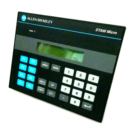
Chapter 2 DTAM Micro Overview Package Contents The DTAM Micro shipping box contains the following: DIP Switch Cover DTAM Micro User Manual Mounting Nuts (8) (Catalog No. 2707–UM002) (2 Spare) Description The front panel of the DTAM Micro terminal is shown below. Figure 2.1 DTAM Micro (front view) LED Indicator... - Page 13 Chapter 2 DTAM Micro Overview Figure 2.2 DTAM Micro (back & bottom view) Back View (RS-232 version shown) Power Connector Communications Port DIP Switch (Behind Removable Cover) Bottom View 2–3...
- Page 14 DTAM Micro Overview Communications Port The DTAM Micro has either an RS-232 or RS-485 port. • Catalog No. 2707-M232P3 has RS-232 port • Catalog No. 2707-M485P3 has RS-485 port DIP Switch A six position DIP switch selects various operating settings. This switch is located under a removable cover on the back.
-
Page 15: Keypad
Chapter 2 DTAM Micro Overview Keypad Figure 2.3 Keypad The DTAM Micro uses a sealed membrane, tactile feedback keypad. The keys are color coded to easily identify key functions. Key Color Function Blue Movement/Operator Response Dark Grey Display/Format Control Light Grey Numeric Entry The following table defines the function of each keypad key. -
Page 16: Function Key Operations
Chapter 2 DTAM Micro Overview Function Key Operations Function keys can be linked to application screens allowing quick access to critical data display or data entry screens. For example, the F1 function key is linked to Recipe Screen 10. The operator can press F1 at any point in the application to download recipe registers on screen 10 to the processor. -
Page 17: Dip Switches
Chapter 2 DTAM Micro Overview DIP Switches The 6 position DIP switch allows you to enable or disable certain functions. The DIP switch is accessed by removing the access cover on the back (access cover is shipped in the hardware bag on new units). Figure 2.4 DIP Switch Side View... -
Page 18: Communications Port
RS-485 Version (Catalog No. 2707-M485P3) DTAM Micro 9 Pin Female (Bottom View) PIN # Signal Name Not Used Receive Data (RD) Transmit Data (TD) Not Used Signal Ground Not Used Not Used Not Used Shield RS-232 Version (Catalog No. 2707-M232P3) 2–8... -
Page 19: Version (Catalog No. 2707-M232P3)
Chapter 2 DTAM Micro Overview RS-232 Communications RS-232 Version (Catalog No. 2707-M232P3) The RS-232 port allows point-to-point communications with: • PLC-5 Channel 0 (configured as RS-232 port, DF1 protocol) • SLC 5/03, 5/04, 5/05 RS-232 port (DH485 protocol) • MicroLogix 1000 Figure 2.6... -
Page 20: Version (Catalog No. 2707-M485P3)
Chapter 2 DTAM Micro Overview RS-485 Communications RS-485 Version (Catalog No. 2707-M485P3) The RS-485 port allows point-to-point and multi-drop communications with: • PLC-5 Channel 0 (configured as RS-422 port, DF1 protocol) • SLC 500 DH-485 port • MicroLogix 1000 using the AIC+ Interface Figure 2.7 Typical RS-485 Communications DTAM Micro to Single SLC... -
Page 21: Programming The Dtam Micro
Chapter 2 DTAM Micro Overview Programming The DTAM Micro is programmed off-line using a personal computer running the DTAM Micro DTAM Plus Programming Software (DPS). Operating system upgrades are also transferred using a personal computer. DTAM Programming Software (DPS) Use DPS software (Catalog No. 2707-NP, Series H or later) to create application screens for both the DTAM Micro and DTAM Plus Operator Terminals. -
Page 22: Default Settings
Chapter 2 DTAM Micro Overview Default Settings The DTAM Micro is preset at the factory with the following defaults: Operating System The DTAM Micro is provided with a default application file: • RS-485 version has DH-485 operating system file • RS-232 version has PLC-5 DF1 operating system file The application file displays a screen with the message: Bul 2707 DTAM Micro... -
Page 23: Product Options
Item Catalog No. Description DTAM Micro 2707-M485P3 DTAM Micro with RS-485 Communications Port DTAM Micro 2707-M232P3 DTAM Micro with RS-232 Communications Port Programming 2707-NP Use to create application screens for the DTAM Micro on Software (Series H or later) a personal computer. Software allows completed applica- tions to be transferred between the DTAM Micro and a per- sonal computer. - Page 24 Chapter 2 DTAM Micro Overview 2–14...
-
Page 25: Initial Setup And Mode Menu
Chapter A–B Initial Setup and Mode Menu Objectives This chapter describes how to apply power to and then configure the DTAM Micro using the menu keys. Instructions on how to use the Simulate mode to run an application are provided. This chapter contains the following sections: Section Page... -
Page 26: Apply Power
Chapter 3 Initial Setup and Mode Main Apply Power This section describes power connections for initial desktop setup and programming. Refer to Chapter 6 for installation wiring instructions. The DTAM Micro is intended for 24 VDC systems. If 24 VDC is not directly available, you can use the AC to DC Adapters: Catalog No. -
Page 27: Powerup Sequence
Chapter 3 Initial Setup and Mode Menu Powerup Sequence The powerup sequence is automatic, you do not have to respond to the screens. The sequence depends upon DIP switch position #1 (upload / download enable). The DTAM Micro is shipped with this switch On. Powerup Sequence (DIP Switch #1 On) 1. -
Page 28: Mode Menu
Chapter 3 Initial Setup and Mode Main Mode Menu Access the Mode Menu by pressing the [MODE] key. All other functions are halted when the menu is displayed. Note: DIP switch SW-3 must be in the On position or the [MODE] key will not function. -
Page 29: Resetting The Dtam Micro
Chapter 3 Initial Setup and Mode Menu Resetting the DTAM Micro Use the reset function to reset the DTAM Micro after DIP switch changes or a configuration change using the Mode Menu. To reset the DTAM Micro: 1. From the Mode Menu select 1 Reset. 1 Reset 3 Special 2 Com-Port... -
Page 30: Setting Communication Parameters Manually
Chapter 3 Initial Setup and Mode Main Setting Communication The Com-Port option on the Mode Menu lets you to manually adjust the Parameters Manually communication port parameters. Normally these parameters are set automatically from the programming software when an application is downloaded. -
Page 31: Special Functions Forcontroller Operations
Chapter 3 Initial Setup and Mode Menu Special Functions for The Special Menu item provides access to special features for the controller Controller Operations operations. A security access code may be assigned in the application restricting access to the Special Menu. Select Special from the Mode Menu. -
Page 32: Entering A New Master Security Code
Chapter 3 Initial Setup and Mode Main Entering a New Master The master security code provides access to all security codes and allows Security Code them to be modified. Two master security codes perform special functions: 00000000 allows the operator to modify the existing master code without entering the current code. -
Page 33: Enabling / Disabling Scaling
Chapter 3 Initial Setup and Mode Menu Enabling / Disabling Scaling Use scaling to convert data from a controller to engineering units such as gallons or psi. When scaling is disabled, the values are not converted. Refer to the DTAM Programming Software Manual for a description of how values are scaled. -
Page 34: Using The Simulate Mode
Chapter 3 Initial Setup and Mode Main Using the The Simulate mode checks an application without having a controller Simulate Mode connected. All data that normally would be sent by the controller, such as data for a display, is set to 0. Any ASCII data is set to ? (PLC5-DF1 operating system only). -
Page 35: Test Functions
Chapter 3 Initial Setup and Mode Menu Test Functions Selecting Test from the Other Menu displays the test screen: DTAM Micro Diag Test < Test Selection > Current Test Selection Use the Test menu to perform the following: • Reset DUT (DTAM Under Test) •... - Page 36 Chapter 3 Initial Setup and Mode Main 3–12...
-
Page 37: Objectives
Chapter A–B Transferring Applications Objectives This chapter describes how to transfer applications between the offline programing software (DPS) and the DTAM Micro. It contains the following sections: Section Page Upload/Download DIP Switch Settings 4–1 Upload/Download Connections 4–2 Computer Setup 4–2 Downloading an Application 4–3 Uploading an Application... -
Page 38: Upload / Download Connections
RS-422 which is compatible with the DTAM Micro RS-485 port. DTAM Micro RS-485 Version (Catalog No. 2707-M485P3) Use Upload/Download Cable (Catalog No. 2707-NC5) RS-232 Version (Catalog No. 2707-M232P3) Use Upload/Download Cable (Catalog No. 2707-NC2) Refer to Chapter 3 for power connections. -
Page 39: Downloading An Application
Chapter 4 Transferring Applications Downloading an Application This section shows how to download an application from a computer running DPS software (Catalog No. 2707-NP, series H or later) to the DTAM Micro. Refer to the DPS Programming Manual (Publication No. 2707-801) for additional information. - Page 40 Chapter 4 Transferring Applications 6. Press any key (other than [Esc]) to continue. The Product Selection Menu appears. . You will not see this prompt if a product type was specified during installation. 7. Press [Return] to select the DTAM Micro product. The Opening Menu appears.
- Page 41 Chapter 4 Transferring Applications 8. Highlight Download File to DTAM Micro and press [Return]. The Communication Port Selection screen appears. . You will not see this screen if a communication port was specified during installation. 9. Highlight the serial port on your computer that is connected to the DTAM Micro (COMM 1 or COMM 2) and press [Return].
- Page 42 Chapter 4 Transferring Applications 12. Press [Return] to load the application file. The download begins and the following screen shows the progress of the download operation. 13. During the download, the DTAM Micro alternately displays: Programming Mode Transfer in Progress Programming Mode Copying to Memory 4–6...
- Page 43 Chapter 4 Transferring Applications 14. When the download is complete, you are returned to the Opening Menu. and the DTAM Micro displays: Programming Mode Waiting Up/Download 15. Press [Esc] to exit the software. 16. Press [Y] to return to DOS. The application is now loaded into the DTAM Micro.
-
Page 44: Uploading An Application
Chapter 4 Transferring Applications Uploading an Application This section shows how to upload an application from the DTAM Micro to a computer running DPS software (Catalog No. 2707-NP, series C or later). Refer to the DPS User manual (Publication No. 2707-801) for additional instructions. - Page 45 Chapter 4 Transferring Applications 6. Press any key (other than [Esc]) to continue. The Product Selection Menu appears. . You will not see this prompt if a product type was specified during installation. 7. Press [Return] to select the DTAM Micro product. The Opening Menu appears.
- Page 46 Chapter 4 Transferring Applications 8. Highlight Upload File from DTAM Micro and press [Return]. The Communication Port Selection screen appears. . You will not see this screen if a communication port was specified during installation. 9. Highlight the serial port on your computer that is connected to the DTAM Micro (COMM 1 or COMM 2) and press [Return].
- Page 47 Chapter 4 Transferring Applications 11. When the upload is complete, you are returned to the Opening Menu. 12. Press [Esc] to exit the software. 13. Press [Y] to return to DOS. The application is now loaded into the DPS software. You can edit the application as described in the DPS Programming Manual (Publication No.
- Page 48 Chapter 4 Transferring Applications 4–12...
-
Page 49: Chapter Objectives
Chapter A–B Running Applications Chapter Objectives This chapter describes screen types and operating procedures that are common to most applications. It contains the following sections: Section Page DIP Switch Setting 5–1 Application Documentation 5–1 Bit Write Mode 5–1 Screen Types 5–2 Screen Navigation 5–2... -
Page 50: Screen Types
Chapter 5 Running Applications Screen Types Application screens can have a variety of appearances. The DTAM Micro can display six types of screens. • Menu and Sub-Menu Screens • Security Screens • Data Display Screens • Data Entry Screens • Recipe Screens •... -
Page 51: Function Keys
Chapter 5 Running Applications Function Keys An application designer can link function keys [F1] through [F8] to individual screens (except alarm screens). Pressing an assigned function key displays the function key number for approximately 0.5 seconds and then the assigned screen. It is the responsibility of the application designer to document the operations assigned to function keys. -
Page 52: Menu And Sub-Menu Screens
Chapter 5 Running Applications Menu and Menus and Sub-Menus provide a convenient method of accessing a large Sub-Menu Screens number of display screens. Main Menu Every application has a Main Menu screen. The Main Menu is the first application screen displayed after an initial power-up or reset. 1 Pump 2 Tank Stat 3 Mixer Stat 4 Recipe... -
Page 53: Data Display Screens
Chapter 5 Running Applications Data Display Screens Data display screens show either the actual or scaled value of a logic controller. Data Display Field Pump 1 Pressure = 150 PSI Counter = 5 Data Display Field Data displays are updated at different intervals depending upon the application and the size of the network. -
Page 54: Recipe Screens
Chapter 5 Running Applications Recipe Screens Recipe screens allow the DTAM Micro to write multiple controller addresses at the same time. Recipe screens can also be linked so that more than one recipe is downloaded. T4:14.2 (Timer Value) N7:30 = 0 (Integer Value) Download Recipe 323? N7:31 = 100 (Integer Value) Press ENTER to send... -
Page 55: Objectives
Chapter A–B Installation Objectives This chapter contains the following sections: Section Page Safety Guidelines 6–1 Operating Environment 6–1 Enclosures 6–2 Equipment Required 6–3 Clearances 6–3 Mounting Dimensions 6–4 Cutout Template 6–5 Installation 6–6 Connecting AC Power 6–7 Safety Guidelines Install the DTAM Micro terminal using publication NFPA 70E, Electrical Safety Requirements for Employee Workplaces as a guide. -
Page 56: Operating Environment
Chapter 6 Installation ATTENTION: EXPLOSION HAZARD: SUBSTITUTION OF COMPONENTS MAY IMPAIR SUITABILITY FOR CLASS 1, DIVISION 2. RISQUE D’EXPLOSION: LA SUBSTITUTION DE COMPOSANTS PEUT RENDRE CE MATÉRIEL INACCEPTABLE POUR LES EMPLACEMENTS DE CLASSE 1, DIVISION 2. ATTENTION CAUTION: USE ONLY WITH CLASS 2 POWER SOURCE LIMITED TO 30 VDC OPEN CIRCUIT AND 8A SHORT CIRCUIT. -
Page 57: Equipment Required
Chapter 6 Installation Equipment Required Other than the tools required to make the panel cutout, the tools required for installation are: • 7mm (M4) deep well socket wrench or nut driver • small slotted screwdriver • torque wrench (in. / lbs). The terminal is tightened against the panel with six self-locking nuts. -
Page 58: Mounting Dimensions
Chapter 6 Installation Mounting Dimensions Figure 6.2 shows the mounting dimensions of the terminal. Figure 6.2 Mounting Dimensions in Inches (Millimeters) Back View (137.2) (99.1) (175.3) Bottom View (137.2) (45.7) 6–4... -
Page 59: Cutout Template
Chapter 6 Installation Cutout Template A cutout template is provided on the inside back cover of this manual to mark the cutout dimensions. Figure 6.3 provides a reference copy, don’t remove this page from the manual. Figure 6.3 Panel Cutout Dimensions in Inches (Millimeters) 6.08 in 3.04 in 3.04 in... -
Page 60: Installation
Mounting nuts must be tightened to a torque of 8 to 10 inch pounds to provide a proper seal and to prevent potential damage to the terminal. Allen-Bradley assumes no responsibility for water or chemical damage to the terminal or other equipment within the enclosure because of improper installation. -
Page 61: Wire And Cable Length Restrictions
Chapter 6 Installation Wire and Cable Length The following wire and cable length restrictions apply to DTAM products Restrictions that are CE marked when used in installations that require compliance to European EMC Directive 89/336: DC Power Wiring 10 meters Ground Terminal Wire 3 meters Communication Cables... - Page 62 Chapter 6 Installation Figure 6.4 DC Power Connections DTAM Micro Use AWG#16 or #14 Stranded Wire To 24 VDC Power Source Optional AC to DC Adapter Catalog No. 1747–NP1, -NP2 To 120VAC (Catalog No. 1747-NP1) To 240VAC (Catalog No. 1747-NP2) 3.
- Page 63 Chapter A–B Communication Connections and Setup Chapter Objectives This chapter describes how to connect the DTAM Micro terminal to and communicate with peripheral devices. It contains the following sections: Section Page Wiring Guidelines 7–1 Connecting RS-232 Devices 7–2 Connecting RS-485 Devices 7–3 Communicating with a Logic Controller 7–6...
- Page 64 Chapter 7 Communication Connections and Setup Connecting The RS-232 port of the DTAM Micro terminal (Catalog No. 2707-M232P3) RS-232 Devices allows point-to-point communications with: • PLC-5 Channel 0 (configured as RS-232 port) • SLC 5/03, 5/04, 5/05 RS-232 port •...
- Page 65 Chapter 7 Communication Connections and Setup Connecting The RS-485 port of the DTAM Micro terminal (Catalog No. 2707-M485P3) RS-485 Devices allows point-to-point and multi-drop communications with: • PLC-5 Channel 0 • SLC Controller DH485 port • MicroLogix 1000 using the AIC+ Interface The figure below shows typical RS-485 connections.
- Page 66 Chapter 7 Communication Connections and Setup DTAM Micro to DH-485 Network DTAM Plus DTAM Micro Terminal Catalog No. 2707-M485P3 SLC 5/01 Cable Cable (Catalog No. 2707-NC1) (Catalog No. 2707-NC1) DH485 Network Link Coupler Link Coupler Interface Converter RS-232 to RS-485 Programming Terminal Link Coupler 7–4...
- Page 67 Chapter 7 Communication Connections and Setup To connect the DTAM Micro terminal to an RS-485 device: 1. Make sure that the power to the DTAM Micro is off. 2. Use the proper cabling to connect the DTAM Micro communications port to the port of the controller (PLC-5 channel 0 or SLC 5/03 RS-232 port).
- Page 68 RS-485 PLC5 DF1 PLC-5 Family channel 0 port (RS-422) (Catalog No. 2707-M485P3) RS-232 PLC5 DF1 PLC-5 Family channel 0 port (RS-232) (Catalog No. 2707-M232P3) RS-485 SLC Family DH-485 port AB DH-485 (Catalog No. 2707-M485P3) MicroLogix 1000 (using AIC+ Interface) RS-485...
-
Page 69: Communication
Chapter 7 Communication Connections and Setup RS-232 Communications The DTAM Micro and PLC-5 must be set as follows for communications with a PLC-5 to occur: PLC-5 DTAM Micro RS-232 Version Channel 0 RS-232C Cable (Catalog No. 2707-NC3) DTAM Micro The DTAM Micro must have an application with a PLC5-DF1 operating system installed. - Page 70 Chapter 7 Communication Connections and Setup RS-232 Communications The DTAM Micro and RS-232 port of the SLC 5/03, 5/04, 5/05 must be set with an SLC 5/03, 5/04, 5/05 as follows for communications to occur: DTAM Micro RS-232 Version SLC 5/03 Channel 0 Gender Adapter...
- Page 71 Chapter 7 Communication Connections and Setup RS-485 Communications The DTAM Micro and SLC DH-485 port must be set as follows for with an SLC or DH-485 communications to occur. If you are using an SLC 5/03, 5/04, 5/05 RS-232 port, refer to the previous section. Network DTAM Micro RS-485 Version...
- Page 72 Chapter 7 Communication Connections and Setup SLC 5/03, 5/04, 5/05 Make sure that the DH-485 network and DTAM Micro parameters match. Parameter Selections Recommended Baud Rate 1200, 2400, 9600, 19.2K 19.2K Node Address 1 to 31 Next lowest address on the network.
- Page 73 Chapter 7 Communication Connections and Setup RS–485/DH–485 The DTAM Micro 485 version has an RS-485 port and uses DH485 protocol. Communications with a It can communicate to the MicroLogix 1000 via DH485 with the AIC+ Interface Converter Module. This is a 3-node network and is not expandable. MicroLogix 1000 DTAM Micro MicroLogix 1000...
- Page 74 Chapter 7 Communication Connections and Setup 7–12...
-
Page 75: Troubleshootingrecommendations
If you encounter a problem that is not listed in the table, contact your local Allen-Bradley distributor for assistance. ATTENTION: Make sure that no objects are inserted or fall into the terminal through the ventilation slots or DIP switch access hole. -
Page 76: Common Operatingproblems
Watch Dog Fault Watch dog timer timed out or pass bits not set. If problem persists, send unit for repair. Push Key to Reset Allen-Bradley SLC 50X Normal display when initiating communications with Attempting to communicate with an SLC. Establishing Comm an SLC. - Page 77 Chapter 8 Troubleshooting and Maintenance Message Probable Cause(s) Corrective Action(s) A master code number of 99999999 may not be Master code is 99999999 and is not user-program- programmed. Download a new, valid master code Not Programmable mable. number (using DTAM Micro Programming Soft- ware).
-
Page 78: Communicationerror Codes
The communication error codes provide valuable information when other symptoms either have not been discovered or have not been understood. Note: For a complete list of error codes, consult the user manuals for your Allen-Bradley controller. The communication error codes specific to the communication protocols are described below. -
Page 79: Using The Test Functions
Chapter 8 Troubleshooting and Maintenance Using the Test Functions Use the test selection screen to test or check the following: • Reset DUT (resets terminal, terminates test function) • DIP switch positions (page 8–6) • Display (page 8–7) • Keyboard (page 8–8) •... -
Page 80: Dip Switch Test
Chapter 8 Troubleshooting and Maintenance DIP Switch Test Use the DIP switch test to verify the DIP switch positions. To perform the DIP switch test: 1. Use the [NEXT] and [PREV] keys to display DIP Switch on the test selection screen. DTAM Micro Diag Test Dipswitch 2. -
Page 81: Display Test
Chapter 8 Troubleshooting and Maintenance Display Test Use the display test to verify that each screen pixel is operating properly. To perform the display test: 1. Use the [NEXT] and [PREV] keys to show Display on the test selection screen. DTAM Micro Diag Test Display Test 2. -
Page 82: Keyboard Test
Chapter 8 Troubleshooting and Maintenance Keyboard Test Use the keyboard test to verify that the keyboard is functioning properly. To perform the keyboard test: 1. Use the [NEXT] and [PREV] keys to display Keyboard on the test selection screen. DTAM Micro Diag Test Keyboard 2. -
Page 83: Communication Port Test
Chapter 8 Troubleshooting and Maintenance Communication Port Test Use the communications test to verify the operation of the RS-232 or RS-485 port. The communications test requires a loopback connector. You can construct a simple loopback connector as follows: RS-232 Port RS-485 Port 9 Pin Female 9 Pin Female... -
Page 84: Ram Test
Chapter 8 Troubleshooting and Maintenance RAM Test Use the RAM test to verify the DTAM Micro Random Access Memory. 1. Use the [NEXT] and [PREV] keys to display RAM on the test selection screen. DTAM Micro Diag Test RAM Test 2. -
Page 85: Program Memory Test
Chapter 8 Troubleshooting and Maintenance Program Memory Test Use the Program Memory test to verify the checksum of the current application file. 1. Use the [NEXT] and [PREV] keys to display System Memory test on the test selection screen. DTAM Micro Diag Test Program Memory 2. -
Page 86: Txen Test
Chapter 8 Troubleshooting and Maintenance TXEN Test Only available on the RS-485 version. Use the TXEN test to verify the transmit enable line at the RS-485 communications port. The TXEN test requires a loopback connector with an LED. You can construct a simple loopback connector as shown below: RS-485 Port Only DB9 Female... -
Page 87: Cleaning The Display Window
Chapter 8 Troubleshooting and Maintenance Cleaning the To clean the display window: Display Window ATTENTION: Use of abrasive cleansers or solvents may damage the window. Do not scrub or use brushes. Some types of paper towels may scratch the window, only use a soft sponge or cloth. - Page 88 Chapter 8 Troubleshooting and Maintenance 8–14...
-
Page 89: Dtam Micro Specifications
Tactile embossed, domed keys, sealed membrane Operation Force 16 oz (453 grams ) Operational Life 1 million operations Electrical Communications Port Catalog No. 2707-M232P3 RS-232 Catalog No. 2707-M485P3 RS-485 (Allen-Bradley DH-485 protocol) Communication Distances RS-232 50 ft (15 meters) maximum... -
Page 90: Agency Ratings
Appendix A Specifications Agency Ratings NEMA Type 4, 12, 13 (indoor use only) Class 1 Division 2 Groups A, B, C, D, hazardous locations (Series B or higher) Class 1 Division 2 Groups A, B, C, D, hazardous locations (Series D or higher) (Series C or higher) Series E Only –... - Page 91 Catalog No. 2707-NC2 Use the Upload/Download Cable to connect the RS-232 version of the DTAM Micro (Catalog No. 2707-M232P3) to a personal computer for transferring applications. A 25– to 9–pin adapter may be required if your computer has a 25–pin communication port.
- Page 92 DTAM Micro Cable Diagrams Catalog No. 2707-NC3 Use the RS-232 Communications Cable to connect the RS-232 version of the DTAM Micro (Catalog No. 2707-M232P3) to Channel 0 (configured as RS-232) of a PLC-5. DTAM Micro RS-232 PLC-5 Channel 0 Port...
- Page 93 Appendix B DTAM Micro Cable Diagrams Catalog No. 2707-NC5 Use the RS-485 Upload/Download Cable to connect the RS-485 port of the DTAM Micro (Catalog No. 2707-M485P3) to a personal computer for transferring applications. The cable contains the circuitry to convert RS-422 signals to RS-232 signals.
- Page 94 Appendix B DTAM Micro Cable Diagrams Catalog No. 2707-NC10 Use the RS-232 Communications cable (Catalog No. 2707-NC10) to connect the DTAM Micro to the MicroLogix 1000 for run-time operation. The length of this cable is 2 meters. DTAM Micro RS-232 Connects to MicroLogix 1000 Communications Port Communications Port...
- Page 95 Catalog No. 1747-CP3 Use this RS-232 Communications Cable to connect the RS-232 port of the DTAM Micro (Catalog No. 2707-M232P3) to Channel 0 of an SLC 5/03. A 9 pin female to male gender adapter is required when using this cable.
- Page 96 Appendix B DTAM Micro Cable Diagrams B–6...
- Page 97 Appendix A–B DTAM Micro Special Controller Functions Objectives This appendix describes the Special Menu used to access to special features for controller operations. Section Page Accessing Special Functions C–1 Using the P-A/D Function C–2 Reading Controller Input and Output Files C–3 Reading / Writing Controller Status Files C–4...
- Page 98 Appendix C DTAM Micro Special Controller Functions The Special Menu provides access to these functions: 1 P-A/D refer to page C–2 for more information. 2 Mode refer to page C–18 for more information. 3 Mem Xfer refer to page C–19 for more information. 4 Clr Fault refer to page C–20 for more information.
- Page 99 Appendix C DTAM Micro Special Controller Functions Reading Controller To read the contents of controller Input and Output files: Input and Output Files 1. Select item 1 from the Special Menu to access the P–A/D function. You are prompted for a file type: Select File Type: (O) Output 2.
- Page 100 Appendix C DTAM Micro Special Controller Functions Reading / Writing To read/write the contents of controller Status files: Controller Status Files ATTENTION: Changing control status bits may cause a processor fault or have other possible effects on the controller operation. Make sure you understand the function of status data. 1.
- Page 101 Appendix C DTAM Micro Special Controller Functions Reading / Writing Controller To read/write the contents of controller Bit and Integer files: Bit and Integer Files 1. Select item 1 from the Special Menu to access the P–A/D function. You are prompted for a file type: Select File Type: (O) Output 2.
- Page 102 Appendix C DTAM Micro Special Controller Functions Reading / Writing Controller To read/write the contents of controller Timer files: Timer Files 1. Select item 1 from the Special Menu to access the P–A/D function. You are prompted for a file type: Select File Type: (O) Output 2.
- Page 103 Appendix C DTAM Micro Special Controller Functions 6. You can change the Acc and Pre values by pressing the [PREV] or [NEXT] keys to move the cursor to the field to change, and then entering a new value. ATTENTION: Do not send negative timer values to the SLC. Negative timer values cause a fault in the SLC.
- Page 104 Appendix C DTAM Micro Special Controller Functions Reading / Writing Controller To read/write the contents of controller Counter files: Counter Files 1. Select item 1 from the Special Menu to access the P–A/D function. You are prompted for a file type: Select File Type: (O) Output 2.
- Page 105 Appendix C DTAM Micro Special Controller Functions 6. You can change the Acc and Pre values by pressing the [PREV] or [NEXT] keys to move the cursor to the field to change, and then entering a new value. 7. Press the [ ] key to enter new accumulator or preset values to the displayed counter address.
- Page 106 Appendix C DTAM Micro Special Controller Functions Reading / Writing Controller To read/write the contents of controller Control files: Control Files 1. Select item 1 from the Special Menu to access the P–A/D function. You are prompted for a file type: Select File Type: (O) Output 2.
- Page 107 Appendix C DTAM Micro Special Controller Functions 6. You can change the Len and Pos values by pressing the [PREV] or [NEXT] keys to move the cursor to the field to change, and then entering a new value. 7. Press the [ ] key to enter new length or position values to the displayed control address.
- Page 108 Appendix C DTAM Micro Special Controller Functions Reading / Writing To read the contents of ASCII files: Controller ASCII Files 1. Select item 1 from the Special Menu to access the P–A/D function. You are prompted for a file type: Select File Type: (O) Output 2.
- Page 109 Appendix C DTAM Micro Special Controller Functions 5. Press [NEXT] to display the binary value of bits 0!15. Data Format File=A012 Elem=002 0011100101010001 Data 6. To change a value, move the cursor into the data field using the [PREV] and [NEXT] keys. Enter the new data. If you are editing binary data, use the [+/-] key to toggle the data between 1 and 0.
- Page 110 Appendix C DTAM Micro Special Controller Functions Reading / Writing To read/write the contents of controller BCD files: Controller BCD Files 1. Select item 1 from the Special Menu to access the P–A/D function. You are prompted for a file type: Select File Type: (O) Output 2.
- Page 111 Appendix C DTAM Micro Special Controller Functions Reading / Writing To read the contents of PLC-5 DF1 message files: Controller Message Files Note: This file type only applies to PLC-5 DF1 operating system. 1. Select item 1 from the Special Menu to access the P–A/D function. You are prompted for a file type: Select File Type: (O) Output...
- Page 112 Appendix C DTAM Micro Special Controller Functions 7. Press [NEXT] to display the value in a binary format: F=MG011 Elem=003.01 0011111000111110 8. To change a value, move the cursor into the data field using the [PREV] and [NEXT] keys. Enter the new data. If you are editing binary data, use the [+/-] key to toggle the data between 1 and 0.
- Page 113 Appendix C DTAM Micro Special Controller Functions Reading Controller To read the contents of PLC-5 DF1 ASCII string files: ASCII String Files Note: This file type only applies to PLC-5 DF1 operating system. 1. Select item 1 from the Special Menu to access the P-A/D function. You are prompted for a file type: Select File Type: (O) Output...
- Page 114 Appendix C DTAM Micro Special Controller Functions Using the Mode Function Use the Mode function to change the controller operating mode (Run or Program) from the DTAM Micro. The mode function displays for an SLC and PLC-5 controller are different. Both are shown below: SLC Controllers 1.
- Page 115 Appendix C DTAM Micro Special Controller Functions Using the Memory The Memory Transfer function allows the DTAM Micro to initiate a memory Transfer Function transfer between a controller memory module and the controller. • Memory transfers with an SLC are bidirectional. Data can be transferred to and from the memory module.
- Page 116 Appendix C DTAM Micro Special Controller Functions Using the Clear Use the Clear Fault function to clear all major and minor faults in the logic Fault Function controller. To clear controller faults: 1. If you are clearing a PLC-5, the controller must be in Program or Remote Program mode.
- Page 117 Index DTAM Micro Operator Interface Module User Manual RS–232 Port, 2–1 RS–485, 2–10 AC Adapter, 2–14, 3–2, 6–7 RS–485 Port, 2–1 Accessories, 2–14 Setting Parameters, 3–6 Upload/Download, 2–12 Adapter, AC, 2–14, 3–2, 6–7 Upload/Download Connections, 4–2 Advisor, 5–2 Communication Port, Test, 8–9 Alarm Screen, 5–6 Compatible Devices, 2–11 Ambient Temperature, Operating, 6–2...
- Page 118 Index DTAM Micro Operator Interface Module User Manual Test, 8–6 Upload/Download Enable, 2–7 Guidelines Upload/Download Setting, 4–1 Safety, 6–1 Display, 2–2 Wiring, 7–1 Cleaning, 8–13 Specifications, A–1 Test, 8–7 Display Test, 3–3 Humidity, Operating, 6–2 Downloading, Applications, 4–3 Description, 2–12, 2–14 Upload/Download, 2–12, 4–3, 4–8 Indicator, LED, 2–2 DTAM Programming Software, See DPS,...
- Page 119 Index DTAM Micro Operator Interface Module User Manual Menu DH485, 2–9, 2–10 Com–Port, 2–6, 3–4 Publications Main, 5–4 DTAM Micro, 1–2 Mode, 2–6, 3–4 PLC–5, 1–3 Other, 2–6, 3–4 SLC, 1–2 Special, 2–6, 3–4, 3–7 Wiring, 1–2 Sub, 5–4 Test, 3–11 Messages, Error, 8–2 Mode RAM, Test, 8–10...
- Page 120 Index DTAM Micro Operator Interface Module User Manual SLC 5/03 Menu, 3–11 Communicating With, 7–8 Program Memory, 8–11 Connection, 7–2, 7–3 RAM, 8–10 Connections, 2–9, 2–10 System Memory, 8–10 Settings, 7–8 Transmit Enable, 8–12 Special Menu, 3–7 Timer File, C–6 Specifications, A–1, B–1, C–1 Transfer, Controller Memory, 3–7 Status File, C–4...
- Page 121 6.08 in 3.04 in 3.04 in 3.04 inch = 77.22 mm 6.08 inch = 154.43 mm 3.97 inch = 100.84 mm .187 in dia. 6 places 3.86 inch = 98.04 mm 4.55 inch = 115.57 5.50 inch = 139.70 mm 0.69 inch = 17.53 mm 0.29 inch...
- Page 124 Publication 2707-UM002C-EN-P - September 2002 PN 40061-236-01(4) Supersedes Publication 2707-UM002B-EN-P - May 2002 Copyright © 2002 Rockwell Automation. All rights reserved. Printed in the U.S.A.
Need help?
Do you have a question about the 2707-M232P3 and is the answer not in the manual?
Questions and answers