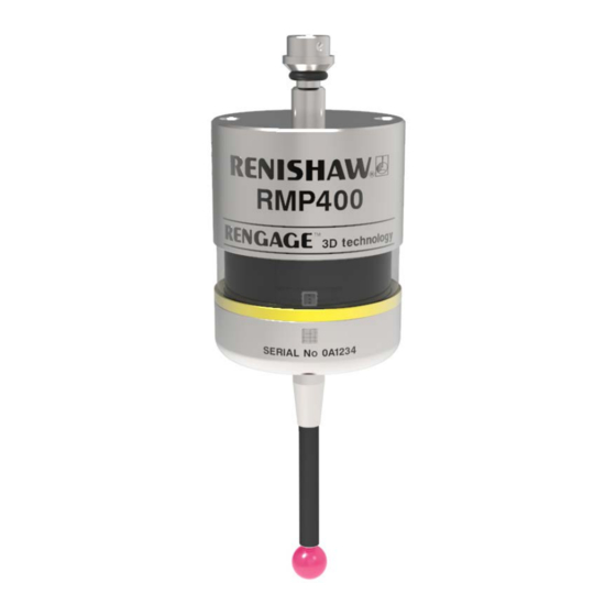
Renishaw RMP400 Installation Manual
High accuracy radio machine
probe
Hide thumbs
Also See for RMP400:
- Quick start manual (264 pages) ,
- Installation manual (54 pages) ,
- Quick start manual (40 pages)

Subscribe to Our Youtube Channel
Related Manuals for Renishaw RMP400


Summary of Contents for Renishaw RMP400
- Page 1 Installation guide H-6570-8501-01-A RMP400 high accuracy radio machine probe Draft 5 16/04/18...
- Page 2 © 2018 Renishaw plc. All rights reserved. This document may not be copied or reproduced in whole or in part, or transferred to any other media or language, by any means, without the prior written permission of Renishaw plc. The publication of material within this document does not imply freedom from the patent rights of Renishaw plc.
-
Page 3: Table Of Contents
RMP400 specification ........ - Page 4 RMP400 installation guide System installation . . . . . . . . . . . . . . . . . . . . . . . . . . . . . . . . . . . . . . . . . . . . . . . . . . . . . . . . . . . 3 .1 Installing the RMP400 with an RMI or RMI-Q .
-
Page 5: Before You Begin
Trade marks • neglected, mishandled or inappropriately used; RENISHAW and the probe symbol used in the RENISHAW logo are registered trade marks of • modified or altered in any way except with the Renishaw plc in the United Kingdom and other prior written agreement of Renishaw. -
Page 6: Patents
Patents Features of the RMP400, and other similar Renishaw products, are the subject of one or more of the following patents and/or patent applications: Patents will be listed here when we have them.. Possibly all RMP40 patents and strain gauge patents... -
Page 7: Eu Declaration Of Conformity
47 CFR Section 15.19 This device complies with part 15 of the FCC Rules. Operation is subject to the following two Renishaw plc declares that the RMP400 complies conditions: with the applicable standards and regulations. This device may not cause harmful... -
Page 8: Radio Approval
Radio approval Will be listed here, when there are some (testing to take place first). Draft 5 16/04/18... -
Page 9: Safety
To reduce the risk of shipment delays, if you need to return the products to Renishaw for any reason, do not return any batteries. In all applications involving the use of machine tools or CMMs, eye protection is recommended. - Page 10 • all screens must be connected as outlined in the user instructions; • cables must not be routed alongside high current sources, i.e. motor power supply cables etc, or be near high-speed data lines; • cable lengths should always be kept to a minimum.
-
Page 11: Rmp400 Basics
• The ability to be used in applications the RMP40, the RMP400 provides existing probe where axial and radial reorientations are users with a simple upgrade to solid-state strain used, enabled by the use of solid state... -
Page 12: System Interface
Trigger Logic review sequence. Probe modes The RMP400 probe can be in one of three modes: Standby mode – Probe is waiting for a switch-on signal. NOTE: The RMP400 will enter hibernation mode... - Page 13 500 rev/min. In “radio on” mode, the switch-on time is user selectable “fast” or “standard” when using The RMP400 must be on for a minimum of RMI-Q (selection is made in RMI-Q). Otherwise one second before being switched off.
-
Page 14: Enhanced Trigger Filter
When the filter is enabled, a constant 8 ms or 16 ms delay is introduced to the probe’s output. Multiple probe mode is a function of the RMP400, The factory setting is 8 ms. If false triggering is as such, the option will not appear when the noticed, then consider increasing the filter delay to “radio on”... -
Page 15: Acquisition Mode
NOTES: Systems using the RMI-Q can be partnered with up to four RMP400s manually. Alternatively this can be achieved by using ReniKey; a Renishaw machine macro cycle which does not require the RMI-Q to be power cycled. For more information or to download ReniKey free of charge visit: www.renishaw.com/mtpsupport/renikey... -
Page 16: Rmp400 Dimensions
RMP400 dimensions 50 (1.97) 19 (0.75) Battery cassette A range of probe-ready shanks is available from Renishaw M4 stylus 11° 11° RMP400 window Probe status LED 50.5 (1.99) Dimensions given in mm (in) Stylus overtravel limits Stylus length ±X/±Y 50 (1.97) 12 (0.47) -
Page 17: Rmp400 Specification
RMP400 specification Principal application Workpiece inspection and job set-up on multi-tasking machines, machining centres and gantry machining centres. Dimensions Length 50.5 mm (1.99 in) Diameter 40 mm (1.57 in) Weight (without shank) With batteries 262 g (9.24 oz) Without batteries 242 g (8.54 oz) - Page 18 230 days 90 days 230 days 90 days 165 hours chloride NOTE: Using RMP400 with “fast radio on” mode will result in a 20% reduction in standby battery life and a 10% reduction in 5% usage battery life. Draft 5 16/04/18...
-
Page 19: Recommended Styli
If a stem RMP400 application and that it may be necessary with a reduced diameter is required, then it is to select specialised styli configurations to meet recommended that an M4 stem with a short length specific application requirements. - Page 20 2.10 This page is intentionally left blank. Draft 5 16/04/18...
-
Page 21: System Installation
RMI-Q are kept within the performance envelope shown overleaf. Coolant and swarf residue accumulating on the RMP400 and RMI or RMI-Q may have a detrimental effect on transmission performance. Wipe clean as often as is necessary to maintain unrestricted transmission. -
Page 22: Positioning The Rmp400 And Rmi Or Rmi-Q
RMP400 radio transmission as it will operate with any reflected radio path provided that the reflected path length does not exceed the 15 m (49.2 ft) operating range. Performance envelope when using the RMP400 with the RMI or RMI-Q 75° 60° 45°... -
Page 23: Preparing The Rmp400 For Use
Preparing the RMP400 for use Fitting the stylus 1.8 Nm – 2.2 Nm (1.3 lbf.ft – 1.6 lbf.ft) M-5000-3707 Draft 5 16/04/18... -
Page 24: Installing The Batteries
Installing the batteries NOTES: See (Section 5,“Maintenance”)for a list of suitable battery types. If dead batteries are inadvertently inserted, the LEDs will remain a constant red. Do not allow coolant or debris to enter the battery compartment. When inserting batteries, check that the battery polarity is correct. -
Page 25: Mounting The Probe On A Shank
Mounting the probe on a shank 2 mm A/F × 2 × 2 2 mm A/F × 4 × 4 2 mm A/F × 2 0.5 Nm – 1.5 Nm (0.4 lbf.ft – 1.1 lbf.ft) Draft 5 16/04/18... -
Page 26: Stylus On-Centre Adjustment
Stylus on-centre adjustment NOTES: × 4 If a probe and shank assembly is dropped, it must be rechecked for correct on-centre adjustment. Do not hit or tap the probe to achieve on-centre adjustment. 360° ±10 µm × 2 × 4 1.5 Nm –... -
Page 27: Calibrating The Rmp400
Calibrating the Calibrating in a bored hole or on a RMP400 turned diameter Why calibrate a probe? Calibrating a probe, either in a bored hole or on a turned diameter of known size, automatically A spindle probe is just one component of the... - Page 28 This page is intentionally left blank. Draft 5 16/04/18...
-
Page 29: Trigger Logic
see Section 4, “Trigger Logic™” Trigger Logic™ Reviewing the probe settings > 5 s LED check Key to the symbols LED short flash LED long flash Switch-on method Radio on Spin on (omitted if “multiple probe mode” is selected) or Switch-off method Radio off or Short timeout... -
Page 30: Multiple Probe Mode Settings
RMP400 installation guide Multiple probe mode settings Deflect the stylus for less than 4 seconds to cycle to the next setting. Multiple probe mode Mode off Mode on Machine 1 Machine 2 Machine 3 Machine 4 Machine 5 Machine 6... -
Page 31: Probe Settings Record
Auto reset off / Trigger filter off Hibernation mode On (30 s) On (5 s) Multiple probe mode Off (factory set) On (machine number) See “Multiple probe settings” Factory settings are for kit (A-6570-0001) only. Draft 5 16/04/18 RMP400 serial no ........ - Page 32 The probe partnering function enables the enter “Acquisition mode”. RMP400 to be partnered with the RMI or RMI-Q “Acquisition mode off” will be displayed as a independently of the configuration process for sequence of light blue flashes, at this point the other probe settings.
- Page 33 Acquisition mode Acquisition mode off Acquisition mode on Acquisition After 8 successful seconds 120 seconds 8 seconds probe in standby probe in standby If acquisition is unsuccessful “Acquisition mode off” will be displayed again after 8 seconds. Deflect the stylus for less than 4 seconds to select “Acquisition mode on”...
-
Page 34: Changing The Probe Settings
RMP400 installation guide Changing the probe settings Insert the batteries or, if they have already been > 5 s installed, remove them for five seconds and then refit them. Following the LED check, immediately deflect the stylus and hold it deflected until eight red flashes have been observed (if the battery power is low, each red flash will be followed by a blue flash). - Page 35 (Renishaw part no. H-4113-8554) or the installation guide RMI-Q radio machine interface (Renishaw part no. H-5687-8504). NOTE: To partner an RMP400 with an RMI NOTE: To partner an RMP400 with an RMI-Q please see “RMP400 – RMI partnership”. Once please see “RMP400 –...
- Page 36 Master reset function To reset the probe First enter into the Trigger Logic™ menu and RMP400 features a master reset function to assist ensure that the stylus is no longer deflected. user’s who have mistakenly changed the probe settings into an unintended state.
- Page 37 “Switch-on method”. Configure probe settings as required using Trigger Logic NOTE: RMP400 will continue to be partnered with either the RMI or RMI-Q following the activation of the master reset function, unless “Multiple probe mode” has been used. Draft 5 16/04/18...
-
Page 38: Rmp400 - Rmi Partnership
Further partnering envelope. will be required if either the RMP400 or RMI In configuration mode, configure the probe is changed, or if a system is reconfigured for settings as required until you reach the multiple probes (multiple probe mode). -
Page 39: Rmp400 - Rmi-Q Partnership
RMP400 – RMI-Q partnership An RMP400 that is partnered with the RMI-Q but then used with another system will need to System set-up is achieved by using Trigger Logic be repartnered before being used again with the and powering on the RMI-Q or applying ReniKey. -
Page 40: Operating Mode
Operating mode LEDs LEDs LEDs flashing flashing flashing green 4.12 Probe status LEDs LED colour Probe status Graphic hint Flashing green Probe seated in operating mode Flashing red Probe triggered in operating mode Flashing green and blue Probe seated in operating mode – low battery Flashing red and blue Probe triggered in operating mode –... -
Page 41: Maintenance
Further dismantling and repair of Renishaw transmission. equipment is a highly specialised operation, which must be carried out at an authorised Renishaw Service Centre. Equipment requiring repair, overhaul or attention under warranty should be returned to your supplier. -
Page 42: Changing The Batteries
Changing the batteries CAUTIONS: Do not leave dead batteries in the probe. When changing batteries, do not allow coolant or debris to enter the battery compartment. When changing batteries, check that the battery polarity is correct. Take care to avoid damaging the battery cassette gasket. - Page 43 NOTES: After removing the old batteries, wait more than 5 seconds before inserting the new batteries. Do not mix new and used batteries or battery types, as this will result in reduced life and damage to the batteries. Always ensure that the cassette gasket and mating surfaces are clean and free from dirt before reassembly.
- Page 44 This page is intentionally left blank. Draft 5 16/04/18...
-
Page 45: Fault-Finding
Incorrect multiple probe mode setting Check configuration and alter as configured. required. RMP400 in hibernation mode (radio Ensure probe is in range and wait on method only). up to 30 seconds, then resend switch-on signal. Check position of RMI or RMI-Q, see operating envelope. - Page 46 Symptom Cause Action Machine stops Radio link failure/RMP400 out of Check interface/receiver and unexpectedly during a range. remove obstruction. probing cycle. RMI or RMI-Q receiver/machine Refer to receiver/machine user’s fault. guide. Dead batteries. Change batteries. Excessive machine vibration Enable enhanced trigger filter.
- Page 47 Machine tool faulty. Perform health checks on machine tool. RMP400 status LEDs do Radio link failure – RMP400 out Check position of RMI or RMI-Q, not correspond to RMI of RMI or RMI-Q range. see operating envelope. or RMI-Q status LEDs.
- Page 48 Probe out of range. Check position of RMI or RMI-Q, see operating envelope. Dead batteries. Change batteries. RMP400 and RMI or RMI-Q are Partner RMP400 with RMI or not partnered. RMI-Q. Probe selection error. Verify that one RMP is working and is correctly selected.
-
Page 49: Parts List
A-2033-0830 Mounting bracket with fixing screws, washers and nuts. Styli tool M-5000-3707 Tool for tightening/releasing styli. Publications. These can be downloaded from our web site at www.renishaw.com. RMP400 H-6570-8500 Quick-start guide: for rapid set-up of the RMP400 probe. RMI QSG A-4113-8550 Quick-start guide: for rapid set-up of the RMI. - Page 50 Renishaw plc +44 (0)1453 524524 +44 (0)1453 524901 New Mills, Wotton-under-Edge uk@renishaw.com Gloucestershire, GL12 8JR United Kingdom www.renishaw.com For worldwide contact details, visit www.renishaw.com/contact *H-6570-8501-01* Draft 5 16/04/18 Issued: ??.???? Part no. H-6570-8501-01-A © 2018 Renishaw plc...
Need help?
Do you have a question about the RMP400 and is the answer not in the manual?
Questions and answers