Renishaw RMP60 Installation Manual
Radio machine probe
Hide thumbs
Also See for RMP60:
- Installation manual (68 pages) ,
- Installation and user manual (47 pages) ,
- Quick start manual (48 pages)
Table of Contents
Advertisement
Advertisement
Table of Contents

Related Manuals for Renishaw RMP60


Summary of Contents for Renishaw RMP60
- Page 1 Installation guide H-5742-8504-02-B RMP60 – radio machine probe...
- Page 2 © 2012–2014 Renishaw plc. All rights reserved. This document may not be copied or reproduced in whole or in part, or transferred to any other media or language, by any means, without the prior written permission of Renishaw plc. The publication of material within this document does not imply freedom from the patent rights of Renishaw plc.
-
Page 3: Table Of Contents
RMP60 specification ........ - Page 4 Installing the RMP60 with an RMI-Q ........
-
Page 5: Before You Begin
Trade marks • neglected, mishandled or inappropriately used; RENISHAW and the probe symbol used in the RENISHAW logo are registered trade marks of • modified or altered in any way except with the Renishaw plc in the United Kingdom and other prior written agreement of Renishaw. -
Page 6: Patents
RMP60 installation guide Patents Features of the RMP60 probe, and other similar Renishaw probes, are subject of one or more of the following patents and/or patent applications: CN 100466003 JP 3967592 CN 101287958 JP 4237051 CN 101482402 JP 4575781 EP 0695926... -
Page 7: Ec Declaration Of Conformity
47 CFR Section 15.19 This device complies with part 15 of the FCC Rules. Operation is subject to the following two Renishaw plc hereby declares that the RMP60 conditions: radio machine probe is in compliance with the essential requirements and other relevant This device may not cause harmful provisions of Directive 1999/5/EC. -
Page 8: Radio Approval
RMP60 installation guide Radio approval Radio approvals Argentina Radio equipment – Canadian warning RMP60 CNC ID: C-13091 RMP60M CNC ID: C-13095 statements Brazil: RMP60Q 0011-14-2812 English RMP60MQ 0011-14-2812 PowerProbe 60 0011-14-2812 Under Industry Canada regulations, this radio transmitter may only operate using an antenna of a type and maximum (or lesser) gain approved for the transmitter by Industry Canada. -
Page 9: Safety
To reduce the risk of shipment delays, if you need to return the products to Renishaw for any reason, do not return any batteries. The RMP60 has a glass window. Handle with care if broken to avoid injury. Information to the machine supplier/... - Page 10 RMP60 installation guide • all screens must be connected as outlined in the user instructions; • cables must not be routed alongside high- current sources, i.e. motor power supply cables etc, or be near high-speed data lines; • cable lengths should always be kept to a minimum.
-
Page 11: Rmp60 Basics
The RMP60 can be used alone or form part of a System interface larger system comprised of multiple radio spindle probes and/or tool setters to function with a single... -
Page 12: Trigger Logic
5 seconds, and then replacing them to activate Shank switch on/Shank switch off the Trigger Logic review sequence. Probe modes The RMP60 probe can be set in one of three modes: Standby mode – Probe is waiting for a switch-on signal. - Page 13 500 rev/min. For more information on the user selectable switch-on time when operating with RMI-Q, please The RMP60 must be on for a minimum of refer to the RMI-Q installation guide. 1 second before being switched off.
-
Page 14: Enhanced Trigger Filter
Enhanced trigger filter NOTES: Probes subjected to high levels of vibration or Multiple probe mode is a function of the RMP60, shock loads may output probe trigger signals as such, the option will not appear when the 'radio without having contacted any surface. The on' option has been selected. -
Page 15: Acquisition Mode
NOTES: Systems using the RMI-Q can be partnered with up to four RMP60s manually. Alternatively this can be achieved by using ReniKey; a Renishaw machine macro cycle which does not require the RMI-Q to be power cycled. For more information or to download Renikey free of charge visit: www.renishaw.com/mtpsupport/renikey... -
Page 16: Rmp60 Dimensions
RMP60 installation guide RMP60 dimensions 50 (1.97) 19 (0.75) Battery cassette Shank switch (optional) A range of probe-ready shanks are available from Renishaw M4 stylus 18° 18° XY overtravel Probe status LED 76 (2.99) Transmission window Dimensions given in mm (in) -
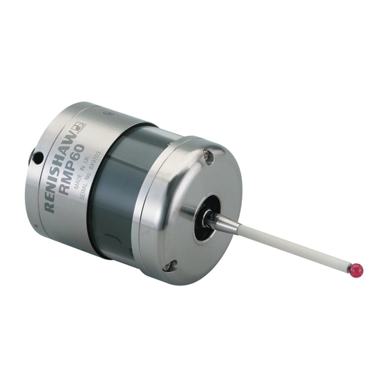
Page 17: Rmp60 Specification
RMP60 specification Principal application Workpiece inspection and job set-up on multi-tasking machines, machining centres and gantry machining centres. Dimensions Length 76 mm (2.99 in) Diameter 63 mm (2.48 in) Weight (without shank) With batteries 876 g (30.90 oz) Without batteries 826 g (29.14 oz) - Page 18 RMP60 installation guide Environment IP rating IPX8 Storage temperature -25 °C to +70 °C (-13 °F to +158 °F) Operating temperature +5 °C to +55 °C (+41 °F to +131 °F) Battery types 2 x AA 1.5 V alkaline or 2 x AA 3.6 V Lithium Thionyl Chloride Battery reserve life Approximately one week after a low battery warning is first given.
-
Page 19: System Installation
This allows easy installation, either inside or outside the machine enclosure. Coolant and swarf residue accumulating on the RMP60 and RMI-Q may have a detrimental effect on transmission performance. Wipe clean as often as is necessary to maintain unrestricted transmission. -
Page 20: Rmp60/Rmi-Q Positioning
Performance envelope RMP60 / RMI-Q positioning The probe system should be positioned so that The RMP60 and RMI-Q must be within each the optimum range can be achieved over the full other's performance envelope as shown below. The performance envelope shows line-of-sight travel of the machine's axes. -
Page 21: Preparing The Rmp60 For Use
Preparing the RMP60 for use Fitting the stylus 1.8 Nm – 2.2 Nm (1.3 lbf.ft – 1.6 lbf.ft) M-5000-3707... - Page 22 NOTE: Must be used with steel styli. For optimum metrology performance do not use a weak link with ceramic or carbon fibre styli. Fitting stylus with weak link onto RMP60 In the event of excessive stylus overtravel, the weak link is designed to break, thereby protecting the probe from damage.
-
Page 23: Installing The Batteries
Installing the batteries NOTES: See Section 5, "Maintenance" for a list of suitable battery types. Ensure the product is clean and dry before inserting batteries. Do not allow coolant or debris to enter the battery compartment. When inserting batteries, check that the battery polarity is correct. -
Page 24: Mounting The Probe On A Shank (Or Machine Table)
Mounting the probe on a shank (or machine table) NOTE: In instances where the RMP60 is to be used with a shank switch, it will be necessary to remove the plug from the rear of the probe using pliers. This should then be substituted with the bobbin (A-4038-0303). -
Page 25: Stylus On-Centre Adjustment
Stylus on-centre adjustment NOTES: During adjustment, care must be taken not to rotate the probe relative to the shank, as damage (x 4) to the bobbin (A-4038-0303) can occur where fitted. 1 Nm If a probe and shank assembly is dropped, it must (0.74 lbf.ft) be rechecked for correct on-centre adjustment. -
Page 26: Stylus Trigger Force And Adjustment
Stylus trigger force is set by Renishaw. The user should only adjust trigger force in special circumstances e.g. where there is excessive machine vibration or insufficient force to support the stylus weight. -
Page 27: Calibrating The Rmp60
Calibrating the RMP60 Calibrating in a bored hole or on a turned diameter Why calibrate a probe? Calibrating a probe, either in a bored hole or on a turned diameter of known size, automatically A spindle probe is just one component of the... - Page 28 RMP60 installation guide 3.10 This page left intentionally blank...
-
Page 29: Trigger Logic
Trigger Logic™ Reviewing the probe settings LED check > 5 s Key to the symbols LED short flash LED long flash Switch-on method Radio on Shank on Spin on (omitted if multiple probe mode is selected) Switch-off method (omitted for shank on) Radio off or Short timeout Medium timeout... -
Page 30: Multiple Probe Settings
RMP60 installation guide Multiple probe settings Deflect the stylus for less than 4 seconds to cycle to the next setting. Multiple probe mode Mode off Mode on Machine 1 Machine 2 Machine 3 Machine 4 Machine 5 Machine 6 Machine 7... -
Page 31: Probe Settings Record
On (10 ms) On (20 ms) Hibernation mode On (30 s) ✔ setting On (5 s) Multiple probe mode Off (factory set) ✔ On (machine number) See "Multiple probe settings" Factory settings are for kit (A-5742-0001) only. RMP60 serial no ........ -
Page 32: Changing The Probe Settings
RMP60 installation guide Changing the probe settings Insert the batteries or, if they have already been > 5 s installed, remove them for five seconds and then refit them. Following the LED check, immediately deflect the stylus and hold it deflected until five red flashes... - Page 33 RMI installation guide (Renishaw part no. H-4113-8554) or the RMI-Q installation guide (Renishaw part no. H-5687-8504). NOTE: To partner an RMP60 with an RMI please NOTE: To partner an RMP60 with an RMI-Q see "RMP60 – RMI partnership". Once acquisition please see "RMP60 –...
-
Page 34: Rmp60 - Rmi Partnership
Further partnering envelope. will be required if either the RMP60 or RMI is In configuration mode, configure the probe changed, or a system is reconfigured for multiple settings as required until you reach the probes (multiple probe mode). -
Page 35: Rmp60 - Rmi-Q Partnership
RMP60 or RMI-Q is changed. "Acquisition mode" menu, which defaults to Any RMP60 that is partnered with RMI-Q, but "Acquisition mode off". then used with another system, will need to be partnered again when it is brought to the RMI-Q. -
Page 36: Operating Mode
RMP60 installation guide Operating mode LEDs LEDs LEDs flashing flashing flashing green Probe status LEDs LED colour Probe status Graphic hint Flashing green Probe seated in operating mode Flashing red Probe triggered in operating mode Flashing green and blue Probe seated in operating mode – low battery Flashing red and blue Probe triggered in operating mode –... -
Page 37: Maintenance
Further dismantling and repair of Renishaw transmission. equipment is a highly specialised operation, which must be carried out at authorised Renishaw Service Centres. Equipment requiring repair, overhaul or attention under warranty should be returned to your... -
Page 38: Changing The Batteries
RMP60 installation guide Changing the batteries CAUTIONS: Do not leave dead batteries in the probe. When changing batteries, do not allow coolant or debris to enter the battery compartment. When changing batteries, check that the battery polarity is correct. Take care to avoid damaging the battery cassette gasket. - Page 39 NOTES: After removing the old batteries, wait more than 5 seconds before inserting the new batteries. Do not mix new and used batteries or battery types, as this will result in reduced life and damage to the batteries. Always ensure that the cassette gasket and mating surfaces are clean and free from dirt before reassembly.
-
Page 40: Diaphragm Replacement
RMP60 installation guide Diaphragm replacement M3 screw RMP60 diaphragms 2.5 mm AF 1 Nm (0.74 lbf.ft) The probe mechanism is protected from coolant and debris by two diaphragms. These provide Cover adequate protection under normal working conditions. Outer You should periodically check the outer diaphragm diaphragm for signs of damage. -
Page 41: Rmp60M System
RMP60M system RMP60M system The RMP60M is a special modular version of the RMP60. It enables probe inspection of part features inaccessible to the RMP60, by fitting selected adaptors and extensions as shown below. See Section 8, "Parts list". RMP60M probe... -
Page 42: Rmp60M Dimensions
RMP60 installation guide RMP60M dimensions 50.50 100/150/200 (1.99) (3.94/5.91/7.87) 67.25 (2.65) 12.50 (0.49) 40.75 50/100/150 (1.60) (1.97/3.94/5.91) 67.25 (2.65) Dimensions mm (in) RMP60M screw torque values 10 Nm to 12 Nm (7.37 lbf.ft to 8.85 lbf.ft) 2.6 Nm (1.92 lbf.ft) 2.6 Nm... -
Page 43: Fault-Finding
Incorrect multiple probe mode Check configuration and alter as setting configured. required. RMP60 in hibernation mode Ensure probe is in range and wait (radio on mode only). up to 30 seconds, then resend switch-on signal. Check position of RMI-Q, see... - Page 44 RMP60 installation guide Symptom Cause Action Machine stops Radio link failure/RMP60 out of Check interface/receiver and unexpectedly during a range. remove obstruction. probing cycle. RMI-Q receiver/machine fault. Refer to receiver/machine user’s guide. Dead batteries. Change batteries. Probe unable to find target Check that part is correctly surface.
- Page 45 Symptom Cause Action Poor probe repeatability Debris on part or stylus. Clean part and stylus. and/or accuracy. Poor tool change repeatability. Redatum probe after each tool change. Loose probe mounting on shank Check and tighten as appropriate. or loose stylus. Environmental or physical Review probing software.
- Page 46 RMP60 installation guide Symptom Cause Action RMP60 status LEDs do Radio link failure – RMP60 out of Check position of RMI-Q, see not correspond to RMI-Q RMI-Q range. operating envelope. status LEDs. RMP60 has been enclosed/ Review installation. shielded by metal.
- Page 47 Symptom Cause Action Probe fails to switch off. Incorrect switch-off method Check configuration and alter as configured. required. No RMI-Q 'start/stop' signal Check RMI-Q for green start LED. (radio on mode only). Probe in timeout mode and Use shorter timeout setting or use placed in tool magazine and is different switch off mode.
- Page 48 RMP60 installation guide This page left intentionally blank...
-
Page 49: Parts List
Parts list Type Part number Description RMP60 A-5742-0001 RMP60 probe with batteries, tool kit and quick-start guide (factory set to radio on/radio off). RMP60M module A-5742-1003 RMP60M module with batteries, tool kit and quick-start guide (factory set to radio on/radio off). - Page 50 LPE3 A-2063-7003 LPE3 extension bar – 150 mm long. A-2063-7600 MA4 90° adaptor assembly. Publications. These can be downloaded from our website at www.renishaw.com RMP60 A-5742-8501 Quick-start guide: for rapid set-up of the RMP60 probe, includes CD with installation guides.
- Page 51 Renishaw plc +44 (0)1453 524524 +44 (0)1453 524901 New Mills, Wotton-under-Edge, uk@renishaw.com Gloucestershire, GL12 8JR United Kingdom www.renishaw.com For worldwide contact details, please visit our main website at www.renishaw.com/contact *H-5742-8504-02* Issued: April 2014 Part no. H-5742-8504-02-B © 2012–2014 Renishaw plc...
Need help?
Do you have a question about the RMP60 and is the answer not in the manual?
Questions and answers