Renishaw RMP400 Installation Manual
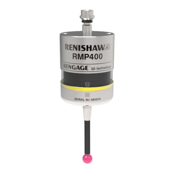
High-accuracy radio machine probe
Hide thumbs
Also See for RMP400:
- Quick start manual (264 pages) ,
- Installation manual (50 pages) ,
- Quick start manual (46 pages)
Table of Contents
Advertisement
Quick Links
Advertisement
Table of Contents

Subscribe to Our Youtube Channel
Related Manuals for Renishaw RMP400


Summary of Contents for Renishaw RMP400
- Page 1 Installation guide H-6570-8501-02-A RMP400 high-accuracy radio machine probe...
- Page 2 This document may not be copied or reproduced in whole or in part, or transferred to any other media or language, by any means, without the prior written permission of Renishaw. Renishaw plc. Registered in England and Wales. Company no: 1106260. Registered office: New Mills, Wotton-under-Edge, Gloucestershire, GL12 8JR, UK.
-
Page 3: Table Of Contents
RMP400 dimensions ........ - Page 4 Positioning the RMP400 and RMI or RMI-Q ........
-
Page 5: Before You Begin
Renishaw office. Renishaw warrants its equipment and software for a limited period (as set out in the Standard Terms and Conditions), provided that they are installed and used exactly as defined in associated Renishaw documentation. -
Page 6: Cnc Machines
Care of the probe Keep system components clean and treat the probe as a precision tool. Patents Features of the RMP400, and other similar Renishaw products, are the subject of one or more of the following patents and/or patent applications: CN 100416216... -
Page 7: Declaration Of Conformity
Declaration of conformity Renishaw plc hereby declares that the RMP400 is in compliance with the essential requirements and other relevant provisions of: • the applicable EU directives • the relevant statutory instruments under UK law The full text of the declaration of conformity is available at: www.renishaw.com/mtpdoc... -
Page 8: Intended Use
RMP400 installation guide Intended use The RMP400 is a radio spindle probe that enables automated workpiece inspection and job set-up on multi-tasking machines, machining centres and gantry machining centres. Safety Information to the user This product is supplied with non-rechargeable lithium metal batteries. Refer to the battery manufacturer’s literature for specific battery operating, safety and disposal guidelines. -
Page 9: Reach Regulation
Information to the equipment installer All Renishaw equipment is designed to comply with the relevant EC and FCC regulatory requirements. It is the responsibility of the equipment installer to ensure that the following guidelines are adhered to, in order for the product to function in accordance with these regulations: •... -
Page 10: Fcc Information To User (Usa Only)
This device must accept any interference received, including interference that may cause undesired operation. 47 CFR Section 15.21 The user is cautioned that any changes or modifications not expressly approved by Renishaw plc or authorised representative could void the user’s authority to operate the equipment. -
Page 11: Radio Approval
Este equipamento não tem direito à proteção contra interferência prejudicial e não pode causar interferência em sistemas devidamente autorizados Canada: IC: 3928A-RMP400 This device complies with Industry Canada licence-exempt RSS standard(s). Operation is subject to the following two conditions: (1) this device may not cause interference, and (2) this device must accept any interference, including interference that may cause undesired operation of the device. - Page 12 RMP400 installation guide TA-2018/1795 South Africa: South Korea: R-C-R1P-RMP400Q Class A Equipment (Industrial Use) 이 기기는 업무용(A급) 전자파적합기기로서 판 매자 또는 사용자는 이 점을 주의하시기 바 라 며, 가정외의 지역에서 사용하는 것을 목적으 로 합니다. Taiwan: CCAK18LP3120T0 警語 經型式認證合格之低功率射頻電機,非經許可,公司、商號或使用者均不得擅自變更頻率、加大功率或 變更原設計之特性及功能。...
-
Page 13: Rmp400 Basics
Performing this calibration for every 3D direction can be time-consuming. The RMP400 has almost no pre-travel variation, so a single calibration value may be used for any probing angle in 2D or 3D. This results in a vastly reduced calibration time. An additional benefit is a corresponding reduction in errors introduced by environmental changes within the machine during a long calibration cycle. -
Page 14: Getting Started
On insertion of batteries, the LEDs will begin to flash, starting with a LED check (for more information, see page 4.1, “Reviewing the probe settings”). System interface The RMI and RMI-Q are integrated interfaces/receivers used to communicate between the RMP400 probe and the machine controller. Trigger Logic™... -
Page 15: Probe Modes
Standby mode – Probe is waiting for a switch-on signal. NOTE: The RMP400 will enter hibernation mode should the system interface be powered off or out of range for a period of 30 seconds (hibernation mode is only applicable to “radio on”). - Page 16 (RF) environment this may rise to a maximum of 3 seconds. In “spin on” mode, the 1 second starts from the moment the spindle reaches 500 r/min. The RMP400 must be on for a minimum of 1 second before being switched off.
-
Page 17: Enhanced Trigger Filter
RMI or RMI-Q. Up to four RMP400 probes can be used with a single RMI-Q in “radio on/radio off” mode. For further details of this functionality, refer to the RMI-Q radio machine interface installation guide (Renishaw part no. -
Page 18: Acquisition Mode
There is no limit to the number of probes that can be used with a single RMI or RMI-Q so long as they all have the same “mode on” colour choice. All RMP400 probes are factory set to “mode off”. -
Page 19: Rmp400 Dimensions
RMP400 dimensions 50 (1.97) 19 (0.75) Battery cassette A range of probe-ready shanks is available from Renishaw M4 stylus 11° 11° RMP400 window Probe status LED 50.5 (1.99) Dimensions given in mm (in) Stylus overtravel limits Stylus length ±X/±Y 50 (1.97) 12 (0.47) -
Page 20: Rmp400 Specification
RMP400 installation guide RMP400 specification Principal application Workpiece inspection and job set-up on multi-tasking machines, machining centres and gantry machining centres. Dimensions Length 50.5 mm (1.99 in) Diameter 40 mm (1.57 in) Weight (without shank) With batteries 262 g (9.24 oz) Without batteries 242 g (8.54 oz) -
Page 21: Typical Battery Life
There may be variation with other batteries (see page 5.3 for suitable battery types). Using RMP400 with “fast radio on” mode will result in a 20% reduction in standby battery life and a 10% reduction in 5% usage battery life. -
Page 22: Recommended Styli
The featured range of solid carbon fibre styli ensure the best possible performance of the RMP400. It is possible that the featured range of solid carbon fibre styli may not be suitable for every RMP400 application and that it may be necessary to select specialised styli configurations to meet specific application requirements. -
Page 23: System Installation
See page 3.2, “Performance envelope”, for further information. Coolant and swarf residue accumulating on the RMP400 and RMI or RMI-Q may have a detrimental effect on transmission performance. Wipe clean as often as is necessary to maintain unrestricted transmission. -
Page 24: Positioning The Rmp400 And Rmi Or Rmi-Q
RMI or RMI-Q is unpowered in “radio-on” (radio-off or timer-off) configurations. The RMP400 goes into hibernation mode 30 seconds after the RMI or RMI-Q is unpowered (or the RMP400 is out of range). When in hibernation mode, the RMP400 checks for a powered RMI or RMI-Q every 30 seconds. -
Page 25: Preparing The Rmp400 For Use
Preparing the RMP400 for use Fitting the stylus 1.8 Nm – 2.2 Nm (1.3 lbf.ft – 1.6 lbf.ft) M-5000-3707... -
Page 26: Installing The Batteries
RMP400 installation guide Installing the batteries NOTES: See Section 5, “Maintenance”, for a list of suitable battery types. If dead batteries are inadvertently inserted, the LEDs will remain a constant red. Do not allow coolant or debris to enter the battery compartment. When inserting batteries, check that the battery polarity is correct. -
Page 27: Mounting The Probe On A Shank
Mounting the probe on a shank × 2 2 mm A/F × 2 2 mm A/F × 4 × 4 2 mm A/F × 2 0.5 Nm – 1.5 Nm (0.4 lbf.ft – 1.1 lbf.ft) -
Page 28: Stylus On-Centre Adjustment
RMP400 installation guide Stylus on-centre adjustment NOTES: If a probe and shank assembly is dropped, it must be rechecked for correct on-centre adjustment. Do not hit or tap the probe to achieve on-centre adjustment. × 4 360° ±10 µm × 2 ×... -
Page 29: Calibrating The Rmp400
Calibrating the RMP400 Why calibrate a probe? A spindle probe is just one component of the measurement system which communicates with the machine tool. Each part of the system can introduce a constant difference between the position that the stylus touches and the position that is reported to the machine. If the probe is not calibrated, this difference will appear as an inaccuracy in the measurement. -
Page 30: Calibrating The Probe Length
RMP400 installation guide Calibrating the probe length Calibrating a probe on a known reference surface determines the length of the probe, based on the electronic trigger point. The stored value for length is different from the physical length of the probe assembly. -
Page 31: Trigger Logic
see Section 4, “Trigger Logic™” Trigger Logic™ Reviewing the probe settings > 5 s LED check Key to the symbols LED short flash LED long flash × Switch-on method (omitted if “multiple probe mode” was selected) Radio on Spin on Switch-off method Radio off or Short timeout... -
Page 32: Multiple Probe Mode Settings
RMP400 installation guide Multiple probe mode settings Deflect the stylus for less than 4 seconds to cycle to the next setting. Multiple probe mode Mode off Mode on Machine 1 Machine 2 Machine 3 Machine 4 Machine 5 Machine 6... -
Page 33: Probe Settings Record
Auto reset on/Filter on (16 ms) Auto reset off/Filter off Hibernation mode On (30 s) setting On (5 s) Multiple probe mode Off (factory set) See “Multiple On (machine number) probe settings” Factory settings are for kit (A-6570-0001) only. RMP400 serial no ........ -
Page 34: Probe Partnering Function
RMI-Q, insert the batteries or, if they have already been installed, remove them for five seconds and then refit them. Following an LED check, the RMP400 will proceed to show the probe settings, this will end with “Battery status” being displayed. If the battery power is good, battery status will be eight green flashes. - Page 35 Whilst the “Battery status” is being displayed, deflect and release the stylus to enter “Acquisition mode off”. Probe status will flash red to acknowledge this. Battery status Battery good Battery low At this point turn on either the RMI or RMI-Q. After 8 Acquisition mode seconds...
-
Page 36: Changing The Probe Settings
RMP400 installation guide Changing the probe settings Insert the batteries or, if they have already been installed, remove them for five seconds and then refit them. Following the LED check, immediately deflect the stylus and hold it deflected until eight red flashes have been observed (if the battery power is low, each red flash will be followed by a blue flash). - Page 37 Switch-off method Radio off or Short Medium Long Spin off timeout timeout timeout 12 s 33 s 134 s Enhanced trigger filter setting and auto-reset facility Auto reset off Auto reset off Auto reset on Auto reset on Auto reset off Trigger filter Trigger filter Trigger filter...
- Page 38 Further probes used require the same “Multiple probe mode” setting, but do not need to be partnered with the RMI or RMI-Q. To partner an RMP400 with an RMI, see page 4.12, “RMP400 – RMI partnership”, or to partner an RMP400 with an RMI-Q, see page 4.13, “RMP400 – RMI-Q partnership”, for further information. Once...
-
Page 39: Master Reset Function
Master reset function RMP400 features a master reset function to assist users who have mistakenly changed the probe settings into an unintended state. The application of the master reset function will clear all current probe settings and return the probe to default settings. - Page 40 RMP400 installation guide 4.10 Battery status Battery good Battery low Switch-on method (omitted if “multiple probe mode” was selected) Radio on Spin on Switch-off method Radio off or Short timeout Medium timeout Long timeout Spin off 12 s 33 s 134 s ×...
- Page 41 Logic menu and will display “Switch-on method”. Configure probe settings as required using Trigger Logic NOTE: RMP400 will continue to be partnered with either the RMI or RMI-Q following the activation of the master reset function, unless “Multiple probe mode” has been used.
-
Page 42: Rmp400 - Rmi Partnership
System set-up is achieved by using Trigger Logic™ and powering on the RMI. Partnering is only required during initial system set-up. Further partnering will be required if either the RMP400 or RMI is changed, or if a system is reconfigured for multiple probes (“Multiple probe mode”). -
Page 43: Rmp400 - Rmi-Q Partnership
4.13 An RMP400 that is partnered with the RMI-Q but then used with another system will need to be repartnered before being used again with the RMI-Q. In configuration mode, configure the probe settings as required until you reach the “Acquisition mode”... -
Page 44: Operating Mode
RMP400 installation guide Operating mode LEDs LEDs LEDs flashing flashing flashing 4.14 green Probe status LEDs LED colour Probe status Graphic hint Flashing green Probe seated in operating mode Flashing red Probe triggered in operating mode Flashing green and blue Probe seated in operating mode –... -
Page 45: Maintenance
Wipe the window of the probe with a clean cloth to remove machining residue. This should be done on a regular basis to maintain optimum transmission. CAUTION: The RMP400 has a glass window. Handle with care if broken to avoid injury. -
Page 46: Changing The Batteries
RMP400 installation guide Changing the batteries CAUTIONS: Do not leave dead batteries in the probe. When changing batteries, do not allow coolant or debris to enter the battery compartment. When changing batteries, check that the battery polarity is correct. Take care to avoid damaging the battery cassette gasket. - Page 47 NOTES: After removing the old batteries, wait more than 5 seconds before inserting the new batteries. Do not mix new and used batteries or battery types, as this will result in reduced life and damage to the batteries. Always ensure that the cassette gasket and mating surfaces are clean and free from dirt before reassembly.
- Page 48 RMP400 installation guide This page is intentionally left blank.
-
Page 49: Fault-Finding
Incorrect multiple probe mode setting Check configuration and alter as configured. required. RMP400 in hibernation mode (“radio Ensure probe is in range and wait on” method only). up to 30 seconds, then resend switch-on signal. Check position of RMI or RMI-Q, see operating envelope. - Page 50 RMP400 installation guide Symptom Cause Action The machine stops Radio link failure/RMP400 out of Check interface/receiver and unexpectedly during a range. remove obstruction. probing cycle. RMI or RMI-Q receiver/machine Refer to receiver/machine user’s fault. guide. Dead batteries. Change batteries. Excessive machine vibration Enable enhanced trigger filter.
- Page 51 Machine tool faulty. Perform health checks on machine tool. RMP400 status LEDs do Radio link failure – RMP400 out Check position of RMI or RMI-Q, not correspond to RMI of RMI or RMI-Q range. see operating envelope. or RMI-Q status LEDs.
- Page 52 Probe out of range. Check position of RMI or RMI-Q, see operating envelope. Dead batteries. Change batteries. RMP400 and RMI or RMI-Q are Partner RMP400 with RMI or not partnered. RMI-Q. Probe selection error. Verify that one RMP is working and is correctly selected.
-
Page 53: Parts List
Section 7,“Parts list” Parts list Item Part number Description RMP400 A-6570-0001 RMP400 probe with batteries, tool kit and quick-start guide (factory-set to radio on/radio off). Battery P-BT03-0007 ½AA battery – lithium-thionyl chloride (pack of two). Stylus A-5003-7306 50 mm long carbon fibre stylus with Ø6 mm ball. - Page 54 Renishaw plc +44 (0)1453 524524 +44 (0)1453 524901 New Mills, Wotton-under-Edge uk@renishaw.com Gloucestershire, GL12 8JR United Kingdom www.renishaw.com For worldwide contact details, visit www.renishaw.com/contact Issued: 08.2021 Part no. H-6507-8501-02-A © 2018–2021 Renishaw plc...
Need help?
Do you have a question about the RMP400 and is the answer not in the manual?
Questions and answers