Table of Contents
Advertisement
Advertisement
Table of Contents

Subscribe to Our Youtube Channel
Related Manuals for Dahua Modular VTO


Summary of Contents for Dahua Modular VTO
- Page 1 Modular VTO (Version 3.1) User’s Manual V1.0.1...
-
Page 2: Cybersecurity Recommendations
Cybersecurity Recommendations Mandatory actions to be taken towards cybersecurity 1. Change Passwords and Use Strong Passwords: The number one reason systems get “hacked” is due to having weak or default passwords. It is recommended to change default passwords immediately and choose a strong password whenever possible. - Page 3 ● Only forward the HTTP and TCP ports that you need to use. Do not forward a huge range of numbers to the device. Do not DMZ the device's IP address. ● You do not need to forward any ports for individual cameras if they are all connected to a recorder on site;...
- Page 4 Ideally, you want to prevent any unauthorized physical access to your system. The best way to achieve this is to install the recorder in a lockbox, locking server rack, or in a room that is behind a lock and key. 15.
-
Page 5: Foreword
Foreword General This document mainly introduces product function, structure, networking, mounting process, debugging process, WEB operation and technical parameters of modular VTO, which is matched with Version 3.12 WEB interface. Models VTO2000A-C, VTO2000A-B, VTO2000A-K, VTO2000A-R and VTO2000A-F. Device Upgrade Please don’t cut off power supply during device upgrade. Power supply can be cut off only after the device has completed upgrade and has rebooted. - Page 6 Version No. Revision Content Release Date V1.0.0 First release 2017.10.31 V1.0.1 Add privacy protection notice 2018.05.23 Privacy Protection Notice As the device user or data controller, you might collect personal data of others' such as face, fingerprints, car plate number, Email address, phone number, GPS and so on. You need to be in compliance with the local privacy protection laws and regulations to protect the legitimate rights and interests of other people by implementing measures include but not limited to: providing clear and visible identification to inform data subject the existence of surveillance...
-
Page 7: Important Safeguards And Warnings
Important Safeguards and Warnings The following description is the correct application method of the device. Please read the manual carefully before use, in order to prevent danger and property loss. Strictly conform to the manual during application and keep it properly after reading. Operating Requirement Please don’t place and install the device in an area exposed to direct sunlight or near heat ... -
Page 8: Table Of Contents
Table of Contents Cybersecurity Recommendations ......................II Foreword ..............................V Important Safeguards and Warnings ....................VII 1 Product Overview ..........................1 1.1 Product Profile ..........................1 1.2 Product Function ........................... 1 2 Product Structure ..........................3 2.1 Camera Module..........................3 2.2 Button Module .......................... - Page 9 6.5 Tamper Switch ..........................46 6.6 Restore Backup........................... 46 7 WEB Config ............................48 7.1 Initialization ..........................48 7.2 Reset the Password ........................49 7.3 System Login ..........................51 7.4 User Manager ..........................52 7.4.1 Add User ........................... 52 7.4.2 Modify User ........................53 7.4.3 Delete User ........................
- Page 10 7.11.4 Import Fingerprint Info..................... 82 7.11.5 Export Fingerprint Info ....................82 7.12 Info Search ..........................83 7.12.1 Call History ........................83 7.12.2 Alarm Record ........................83 7.12.3 Unlock Record ........................ 83 7.13 Reboot Device........................... 84 7.14 Logout ............................84 8 FAQ ............................... 85 Appendix 1 Technical Parameters ......................
-
Page 11: Product Overview
Product Overview Product Profile Modular VTO consists of camera module, one-button module, three-button module, five-button module, keyboard module, card swiping module and fingerprint module. Camera module is indispensable, whereas other modules can be matched flexibly, and can combine with VTH, VTS and platform to establish a video intercom system. - Page 12 Alarm Support tamper alarm, door sensor alarm and alarm of unlock with duress password. Meanwhile, report the alarm info to Management Center. Record Search Search call records, alarm records and unlock records.
-
Page 13: Product Structure
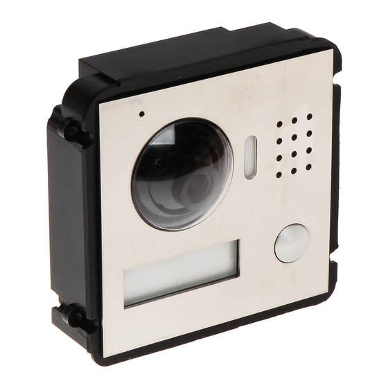
Product Structure Camera Module Figure 2-1 Name Description User directory Display user info. Call key Call the user or management centre. Microphone Audio input. Camera Monitor the door area, with adjustable angle. Fill-in light Provide fill-in light for camera in case of insufficient light. Speaker Audio output. - Page 14 Figure 2-2 Name Description Camera angle Adjust camera angle. adjusting column When VTO is detached from the wall forcibly, give out alarm Tamper switch sound and report alarm info to management centre. Network port Connect network cable (RJ45 plug) through a connection line. Provide power port, lock port, door sensor feedback port and exit button port to connect power supply, electric control lock, User port...
-
Page 15: Button Module
Figure 2-3 Figure 2-4 Button Module Button module consists of one-button module, three-button module and five-button module; their functions are the same, although button quantity is different. Take “three-button module” for example. - Page 16 Figure 2-5 Name Description User directory Display user info according to buttons. Call key Call the VTH. Table 2-3 Figure 2-6 Name Description Cascade input port Connect other modules. Cascade output port Table 2-4...
-
Page 17: Keyboard Module (With Braille)
Keyboard Module (with Braille) Rear panel of keyboard module is the same as rear panel of button module. Figure 2-7 Name Description Call management centre Call management centre. Input the password. For example, unlock password is Numeric key 123456. Please input “#+ unlock password +#”. Call key Call the VTH. -
Page 18: Fingerprint Module
Figure 2-8 Name Description Card swiping area It is valid to swipe the card here. When a person is about 1m away from the device, the device will sense the person’s approaching. Backlights of display Proximity sensor screens of all modules and the keyboard will be turned on automatically. -
Page 19: Blank Module
Figure 2-9 Name Description Fingerprint module The user inputs a fingerprint or unlocks with a fingerprint. Table 2-7 Blank Module Rear panels of blank module and button module have different port positions, but port functions are the same. - Page 20 Figure 2-10 Name Description User directory Display user info according to buttons. Table 2-8...
-
Page 21: Networking Diagram
One-to-one Scene Modular VTO connects with VTH directly. A visitor presses call key on VTO to call the resident (VTH) or Management Center. Networking diagram is shown in Figure 3-1. If keyboard module is connected, dial VTH room number to call. -
Page 22: Group Call Scene
Figure 3-2 Group Call Scene When the visitor presses call key on modular VTO, multiple VTHs ring at the same time; the resident can pick up, hang up or unlock on any VTH. Networking diagram is shown in Figure 3-3. - Page 23 Figure 3-3...
-
Page 24: Device Mounting
Device Mounting Modular VTO consists of single module mounting, double module mounting and 3-module mounting. Take 3-module mounting for example. When leaving factory by default, visiting cards and card cover have been included in the attachment. When power-on after mounting, please ensure that all modules have been connected;... - Page 25 Figure 4-1 Figure 4-2...
-
Page 26: Flush Mounting
Flush Mounting Step 1 Dig a hole in the wall. Regarding single module mounting, hole dimension is 115mm×115mm×57mm. Regarding double module mounting, hole dimension is 237mm×125mm×50mm. Regarding 3-module mounting, hole dimension is 349mm×125mm×50mm. Step 2 Embed flush mounting box into the wall; ensure that box edge clings to the wall. Step 3 Fix every module onto front panel with M3×6 screws. - Page 27 Figure 4-4...
-
Page 28: Device Debugging
Device Debugging Debugging Settings 5.1.1 VTO Settings 5.1.1.1 Initialization For the first time, please initialize login password. Please ensure that default IP addresses of PC and VTO are in the same network segment. Default IP address of VTO is 192.168.1.110. Step 1 Connect power supply of VTO, and power on. - Page 29 Figure 5-2 Select “Email” and enter your Email address. Step 4 This Email address is used to reset the password, so it is recommended that it should be set. Click “Next”. Step 5 The system displays “OK” interface, as shown in Figure 5-3 错误!未找到引用源。, and shows “Device succeeded!”...
- Page 30 Figure 5-4 Enter user name and password, and click “Login”. Step 7 Log in the WEB interface of the device. Default user name is admin. Password is the one set during initialization. 5.1.1.2 Modify Device Network Modify IP address of VTO to the planned IP address. Select “System Config>...
- Page 31 5.1.1.3 LAN Config Configure VTO building no., unit no. and VTO no. info. Select “System Config> LAN Config”. Step 1 The system displays “LAN Config” interface, as shown in Figure 5-6. Figure 5-6 Enter VTO “Building No.”, “Building Unit No.” and “VTO No.”. Step 2 To call the management centre, please tick “Register to the MGT Centre”, and set ...
- Page 32 Figure 5-7 Click “Add”. Step 2 The system displays “Add” interface, as shown in Figure 5-8. Figure 5-8 Enter VTH “Family Name”, “First Name”, “Nick Name”, “VTH Short No.” (VTH room no.) Step 3 and “IP Address”. It is OK if IP address is not filled in. After VTH is registered to VTO successfully, VTO will obtain IP address of VTH.
- Page 33 Figure 5-9 Step 2 Click The system displays available modules, as shown in Figure 5-10. Figure 5-10 If keyboard module, card swiping module and fingerprint module have been added already, they are not displayed here. Step 3 Select modules according to actual layout of VTO. ...
-
Page 34: Vth Settings (Version 3.1)
Figure 5-11 Select room no. and click “OK”. Step 5 The interface displays room no. info and corresponding button turns green, as shown in Figure 5-12. Figure 5-12 Click “Save” to save the settings. Step 6 After saving, reboot the device to take effect. 5.1.2 VTH Settings (Version 3.1) 5.1.2.1 Initialization Set the password and bind your Email. - Page 35 Figure 5-13 Enter “Password”, “Confirm Pwd” and “Email”. Step 2 Step 3 Click [OK]. The system displays “Info Init” interface, and click to turn off the interface. 5.1.2.2 Network Settings Set VTH network info, which supports static IP and DHCP. IP addresses of VTH and VTO shall be in the same network segment.
- Page 36 Figure 5-14 Step 4 Set according to actual network access mode. Static IP Select “Static IP”. Enter “Local IP”, “Subnet Mask” and “Gateway”. DHCP Select “DHCP” to obtain IP address automatically. Step 5 Click [OK] to save the settings. 5.1.2.3 Product Info Settings Set VTH “Room No.”, “Type”...
- Page 37 Figure 5-15 Step 4 Set VTH info. Be used as a master VTH. Enter “Room No.” (such as 9901). “Room no.” shall be the same with “VTH Short No.”, which is set when adding VTH at WEB interface. Otherwise, it will fail to connect VTO. ...
-
Page 38: Vth Settings (Version 4.0)
Figure 5-16 Step 4 Add VTO or fence station. Add main VTO. In Figure 5-16, enter main VTO name, IP address, “User Name” and “Password”. Switch “Enable Status” to “User Name” and “Password” shall be consistent with WEB login user name ... - Page 39 Step 1 Power on the device. The system displays “Welcome” and enters “Device Initialization” interface, as shown in Figure 5-17. Figure 5-17 Enter “Password”, “Confirm Pwd” and “Email”. Click [OK]. Step 2 The system displays main interface. 5.1.3.2 Network Settings Set VTH network info according to actual network access mode.
- Page 40 Figure 5-18 Figure 5-19 Step 4 Set according to actual network access mode. Wired IP Enter “Local IP”, “Subnet Mask” and “Gateway”, press [OK]. Or press to enable DHCP function and obtain IP info automatically. If the device has wireless function, please click “Wired IP” tab to set it. WLAN ...
- Page 41 Figure 5-20 Connect WIFI. The system has 2 access ways as follows. At “WLAN” interface, select WIFI, click “Wireless IP” tab to enter “Local IP”, ◇ “Subnet Mask” and “Gateway”, and press [OK]. At “WLAN” interface, select WIFI, click “Wireless IP” tab, press ◇...
- Page 42 The system pops up “Password” prompt box. Step 2 Enter the password set during initialization, and click [OK]. Step 3 Click [VTH Config]. The system displays “VTH Config” interface, as shown in Figure 5-22. Figure 5-22 Step 4 Set VTH info. Be used as a master VTH.
-
Page 43: Debugging Verification
Figure 5-23 Step 4 Add VTO or fence station. Add main VTO. In Figure 5-23, enter main VTO name, VTO IP, “User Name” and “Password”. Switch the “Enable Status” to be “User Name” and “Password” shall be consistent with WEB login user name ... - Page 44 Figure 5-24 5.2.1.2 VTH Monitors VTO VTH is able to monitor VTO, fence station or IPC. Take “VTO” for example. Select “Video Talk > Monitor > Door Station”, as shown in 错误!未找到引用源。 . Select the VTO to enter monitoring image, as shown in Figure 5-26. Figure 5-25...
-
Page 45: Verification With Version 4.0 Vth
Figure 5-26 5.2.2 Verification with Version 4.0 VTH 5.2.2.1 VTO Calls VTH Press call key at VTO or dial VTH room no. (9901) to call VTH. VTH pops up monitoring image and operating keys, as shown in 错误!未找到引用源。. It represents successful debugging. The following figure means that SD card has been inserted into VTH. - Page 46 5.2.2.2 VTH Monitors VTO VTH is able to monitor VTO, fence station or IPC. Take “VTO” for example. Select “Monitor > Door”, as shown in Figure 5-28. Select the VTO to enter monitoring image, as shown in Figure 5-29. The following figure means that SD card has been inserted into VTH. If SD card is not inserted, recording and snapshot icons are gray.
-
Page 47: Basic Function
Basic Function Call Function 6.1.1 Call Management Centre The system provides different calling ways depending on connected module. If modular VTO connects keyboard module, press on the keyboard module to call the management centre. If keyboard module is not connected, press call key of camera module to call the management centre. -
Page 48: Single Call Of Vth
Figure 6-1 6.1.2 Single Call of VTH Single call applies to the scene where one door corresponds to one VTH. The system provides different calling ways depending on connected module. Make a single call from camera module Confirm the following configurations before call; press the call key of camera module to call VTH. - Page 49 Figure 6-2 Confirm whether call key is bound with VTH, as shown in Figure 6-3. Please refer to “7.7.2 Facade Layout” for details. Figure 6-3 Make a group call from button module Ensure that button module has been connected and added to faç ade layout. Otherwise, this call doesn’t exist.
-
Page 50: Group Call
Figure 6-4 Make a group call from keyboard module Ensure that keyboard module has been connected and added to faç ade layout. Otherwise, this call doesn’t exist. On keyboard module, press VTH room no. and press to call the VTH. 6.1.3 Group Call Group call applies to the scene where one VTO corresponds to multiple VTHs. - Page 51 Confirm the following configurations before call; press the call key of camera module to call master VTH, and call other extension VTHs simultaneously. Ensure to cancel the selection of “Call VTS or Not”, as shown in Figure 6-5. Confirm whether call key is bound with master VTH, as shown in Figure 6-6. Please refer ...
-
Page 52: Unlock Function
Figure 6-7 Make a group call from keyboard module Ensure that keyboard module has been connected and added to faç ade layout. Otherwise, this call doesn’t exist. On keyboard module, dial master VTH room no. and press to call the master VTH, and call other extension VTHs simultaneously. -
Page 53: Unlock With Ic Card
Figure 6-8 6.2.3 Unlock with IC Card Swipe the authorized IC card at card swiping module, so as to open the door. This function is valid only when card swiping module has been connected. Authorized IC card refers to a card that is issued and authorized to open the door. For card ... -
Page 54: Issue Card
6.2.5.2 Unlock with Unified Password In standby mode, press , enter unified password (default password is 123456), and press again to unlock. For example, XX user presses #123456# to unlock. 6.2.5.3 Unlock with Duress Password In case of duress, press , enter duress password (default password is 654321) , and press again to unlock. -
Page 55: Monitoring Function
Figure 6-10 Step 3 Within 30s countdown, swipe an unauthorized card at VTO. The system pops up “Card Info” interface, as shown in Figure 6-11. Figure 6-11 Enter “Room No.” and “Card No.”. Click “OK”. Step 4 Cards can be swiped continuously, within a period of 30s. Click “OK”... -
Page 56: Tamper Switch
Figure 6-12 Tamper Switch Camera module is equipped with a tamper switch against the wall. In case that the device is disassembled from the wall, tamper switch will leave the wall too. The device will emit tamper alarm sound and report alarm info to management centre. Restore Backup If VTH info is modified by mis-operation during use, two restoration ways are available to restore them. - Page 57 Figure 6-13 Select “VTH Info” and click “Restore Backup”. Step 2 Backup VTH info in the device will be restored to VTO. Restore from local backup data Select “System Config >Indoor Manager”. Step 1 The system displays “Digital Indoor Station Manager” interface, as shown in Figure 6-14.
-
Page 58: Web Config
WEB Config Initialization For the first login or login after restoring factory defaults, please initialize WEB interface. Please ensure that default IP addresses of PC and VTO are in the same network segment. Otherwise, it fails to enter initialization interface. Step 1 Enter default IP address of VTO at the address bar of PC browser, and press [Enter] key. -
Page 59: Reset The Password
Figure 7-2 Select “Email” and enter your Email address. Step 3 This Email address is used to reset the password, so it is recommended that it should be set. Click “Next”. The system displays “OK” interface, as shown in Figure 7-3 and shows Step 4 “Device succeeded!”... - Page 60 Step 1 Log in WEB interface of the device through browser,. The system displays login interface, as shown in Figure 7-4. Figure 7-4 Click “Forgot Password”. Step 2 The system displays “Reset the password” dialog box, as shown in Figure 7-5. Figure 7-5 Step 3 Scan the QR code according to interface prompts and obtain security code.
-
Page 61: System Login
The system displays new password setting interface, as shown in Figure 7-6. Figure 7-6 Set “New Password” and “Confirm”. Step 6 Password can be 8 to 32 non-null characters; it consists of letters, numbers and symbols (except “'”, “"”, “;”, “:” and “&”). The password shall consist of 2 types or over 2 types. -
Page 62: User Manager
Figure 7-7 Enter username and password, and click “Login”. Step 2 Log in the WEB interface of the device. Default username is admin. Password is the one set during initialization. User Manager Add, delete and modify WEB user info. Select “System Config >... -
Page 63: Modify User
Figure 7-9 Enter “Username”, “Password”, “Confirm” and remark. Step 2 Password is required to be at least 8 characters, and shall include at least two types of number, letter and symbol. Click “OK” to complete adding. Step 3 7.4.2 Modify User 7.4.2.1 Modify Admin User Admin user can modify his/her own user password and Email address. - Page 64 The system displays password change interface, as shown in Figure 7-11. Figure 7-11 Enter “Old Password”, “New Password” and “Confirm”. Tick “Modify Email” to enter Email address. Click “OK”. 7.4.2.2 Modify Ordinary User Ordinary user refers to other uses except admin user. Admin user can modify remark and password of all other users, while ordinary user can modify his/her own password only.
-
Page 65: Delete User
Figure 7-13 Enter “Old Password”, “New Password” and “Confirm”. Update remark. Click “OK”. 7.4.3 Delete User Click in the line of user info that requires deletion, in order to delete this user. Network Parameter Config Set IP address, FTP server, application port, DDNS, HTTPS, UPnP and IP authority. 7.5.1 Network Config Set IP address of VTO. -
Page 66: Ftp Server
Figure 7-14 Enter the planned “IP Address”, “Subnet Mask” and “Default Gateway”. Step 2 Step 3 Turn on SSH according to needs. After SSH is on, Telnet and other debugging terminals can connect VTO, operate and debug it. Click “OK” to save the settings. Step 4 7.5.2 FTP Server Set FTP server, so recordings and snapshots will be saved in FTP server. - Page 67 Figure 7-16 Step 2 Set port value of this device and refer to Step 3 Description Communication port of TCP protocol, to be set according to the user’s actual TCP Port needs. It is 37777 by default. User datagram protocol port, to be set according to the user’s actual needs. UDP Port It is 37778 by default.
- Page 68 Step 3 Description follows: rtsp://admin:admin@10.12.4.84:554/cam/realmonitor?channel=2&subtype= If certification is unneeded, it is unnecessary to designated username and password. Use the following format: rtsp://ip:port/cam/realmonitor?channel=1&subtype=0 Step 4 Table 7-2 for details. Parameter Description Communication port of TCP protocol, to be set according to the user’s actual TCP Port needs.
-
Page 69: Ddns Server
Parameter Description rtsp://ip:port/cam/realmonitor?channel=1&subtype=0 Table 7-2 Click “OK” to save the settings. Step 5 In case that the port is modified, enter “http://VTO IP: WEB port no.” in the browser, to visit WEB interface of this VTO. 7.5.4 DDNS Server In case of frequent changes in IP address of the device, DDNS (Dynamic Domain Name Server) dynamically updates the relation between domain name and IP address on DNS server, and ensures that users are able to visit the device through domain name. -
Page 70: P2P
Step 4 Parameter Description name and password) at the website of DDNS server provider. The time interval to raise update request after DDNS Live Time designated DDNS update is enabled. The unit is second. Step 5 Table 7-3 for details. Parameter Description Server type refers to name of DDNS server provider. -
Page 71: Https Setting
Figure 7-18 Tick “Enable” to enable P2P function. Step 2 Select “P2P Server”. Step 3 Click “OK” to complete setting. Step 4 After the setting has been completed, “Status” becomes “Online”, representing successful P2P registration. After successful P2P registration, enter the serial number directly to add VTO, in order to visit and manage VTO. -
Page 72: Upnp
7.5.7 UPnP Via UPnP protocol, create mapping relationship between private network and WAN. WAN user can visit device in LAN via outer IP address. Please confirm the following operation before use. UPnP function is used only when VTO is connected with router. ... - Page 73 Figure 7-21 Step 2 Set parameters and refer to Step 3 Parameter Description Tick “Enable” to enable the mapping relation. Enable/ Tick “Disable”, meaning that mapping Disable relation is not enabled. Choose to enable it in the external list. Server Name Name of network server.
- Page 74 Parameter Description Server Name of network server. Name Protocol Protocol type. Port that When you set router mapping outer port, try to use port this device Inport within 1024~5000, avoid using well-known port 1~255 needs and system port 256~1023, in order to prevent conflicts. map.
-
Page 75: Ip Purview
7.5.8 IP Purview In order to strengthen device network security and protect device data, set access purview of IP host (IP host refers to personal computer or server with IP). White list allows designated IP host to visit the device. ... -
Page 76: Lan Config
The system supports to set maximum 64 IP addresses. Type Description Add host IP address to be added; adopt IPv4 format, such IP Address as 192.168.1.120. Enter the start address and end address of network IP Network Segment segment to be added. Table 7-5 Click “OK”. -
Page 77: Local Parameter Config
Parameter Description Index”. If call key of the camera has been bound with master VTH, press the call key to make a call. If VTO has been connected with button module and bound with master VTH, press the call key to make a call. If VTO has been connected with keyboard module, dial room no. -
Page 78: Facade Layout
Figure 7-27 Step 2 Set parameters and refer to Step 3 Parameter Description If it is dark during video intercom, turn on the fill-in Sensor light automatically. The larger the value is, the higher sensitivity becomes. Device Type It is villa station by default. Reboot Date Set auto reboot time of VTO. - Page 79 Figure 7-28 Step 2 Click The system displays available modules, as shown in Figure 7-29. If keyboard module, card swiping module and fingerprint module have been added already, they are not displayed here. Figure 7-29 Step 3 Select modules according to actual layout of VTO. Actual connection position of the device on WEB interface is from top to bottom and from left to right.
- Page 80 Figure 7-30 Step 2 Click The system displays “Room Config”, as shown in Figure 7-31. The displayed room no. is the added VTH. To add VTH, please refer to “7.8.1 Add VTH”. Click to modify the bonded buttons when necessary. ...
-
Page 81: Access Manager
Figure 7-32 Click “Save” to save the settings. Step 4 After saving, reboot the device to take effect. 7.7.3 Access Manager Set unlock responding interval, unlock period, door sensor check time, unlock password, menace password, auto snapshot and issue card.. Select “System Config >Local Config >... - Page 82 Parameter Description Unlock Responding After unlock, the interval that the device responds to the next unlock. The unit is “second”. Interval After unlock, the period that it remains unlocked. The unit is Unlock Period “second”. Tick “Check Door Sensor Signal Before Lock” to enable the Check Door Sensor...
-
Page 83: Sound Control
7.7.4 Sound Control Enable and disable unlock sound, ringtone, alarm sound and speech sound. Select “System Config >Local Config > Sound Control”. Step 1 The system displays “Sound Control” interface, as shown in Figure 7-34. Figure 7-34 Step 2 Enable or disable corresponding sound. Click “OK”... -
Page 84: System Time
Parameter Description Press [1] to leave a picture/message. The system will upload the contents to FTP and messages are available at “Visitors’ Message” tab. Upload Talk Reserved function. Record Table 7-9 Click “OK” to save the settings. Step 3 7.7.6 System Time Set system date format, time format, system time and NTP server. -
Page 85: Config Manager
Step 3 Parameter Description Set the start time and end time of DST. Tick “NTP Enable” to enable this function. NTP Enable NTP Server Enter domain name or IP address of NTP server. Zone Select time zone of the device. Port No. -
Page 86: Indoor Manager
Figure 7-37 Backup Select “VTH Info”, and click “Backup”, so VTH info will make a backup in VTO. Restore Backup Click “Restore Backup”, so card info and VTH info is restored to backup info. Export Config Click “Export Config” to export config info and save it at local device, so as to restore config or import into other devices. -
Page 87: Modify Vth
Figure 7-39 Step 2 Set parameters and refer to Step 3 Parameter Description Family Name Set VTH user name and nick name, in order First Name to identify VTH. Nick Name Set VTH room no.. VTH Short No. VTH short no. is the same as room no. configured at VTH. -
Page 88: Delete Vth
Figure 7-40 Modify VTH “Family Name”, “First Name” and “Nick Name”. Step 2 Click “OK” to save the settings. Step 3 7.8.3 Delete VTH Click to delete VTH info one by one. 7.8.4 QR Code Every VTH provides a QR code. Connect mobile phone client with P2P function, so all info is pushed to the client, in order to receive and view them conveniently. -
Page 89: Config Manager
7.8.5 Config Manager Import or export device info, password info, card no. info and login info of the device. 7.8.5.1 Export Config Export and save config in the local device. When other devices need to configure the same parameters, the config file can be imported. Click “Export Config”. - Page 90 Figure 7-43 Modular VTO doesn’t support main card function. Step 2 Click to report loss, and the icon is switched to Click to cancel the report and restore unlock function. Step 3 Click to close config interface. 7.8.6.2 Modify Modify username of the card.
-
Page 91: Video Set
Video Set Set video picture and audio volume of VTO with camera. 7.9.1 Video Set Select “System Config >Video Set>Video Set”. Step 1 The system displays “Video Set” interface, as shown in Figure 7-45. Click “Open Door”, and VTO is unlocked. Figure 7-45 Step 2 Set parameters and refer to... - Page 92 Step 3 Parameter Description more contrasted the image becomes; and vice versa. When this value is large, dark part of the image is too dark, while bright part overexposes easily. When this value is small, the image dims. Adjust image hue. There is a default value according to sensitometric feature of the sensor.
- Page 93 Step 3 Parameter Description Select “On”; the image will be turned over from left to Mirror right. Select “On”; the image will be turned over from top to Flip bottom. Step 4 Table 7-12 for details. Parameter Description Video Format Adjust resolution of video, including 720P, WVGA and D1.
-
Page 94: Audio Set
Parameter Description There are several modes: Disabled: no backlight. Backlight: prevent silhouette appearing in dark part of the subject against the light. Wide dynamic: according to ambient brightness, the system Backlight Mode reduces brightness of high-brightness area, increases brightness of low-brightness area, and thus displays both areas clearly. -
Page 95: Add One Ipc
Figure 7-47 7.10.1 Add One IPC Add IPC info one by one. Add IPC directly, or add NVR/XVR/HCVR devices to obtain info about the added IPC. Step 1 Click The system displays “Modify” interface, as shown in Figure 7-48. Figure 7-48 Step 2 Set parameters and refer to Step 3... -
Page 96: Delete
Step 3 Parameter Description Username Enter the username and password to login Password WEB interface of IPC/NVR/XVR/HCVR. Port No. It is 554 by default. It consists of local protocol and Onvif protocol. Please select according to the Protocol protocol supported by the connected device. -
Page 97: Batch Import
7.10.3 Batch Import With batch import function, import IPC info into the system. Click “Import Config”, select config file (.csv) and import the file info into the system. 7.10.4 Batch Export Export and save the present IPC info to the local device, for the sake of future use. Click “Export Config”;... -
Page 98: Modify Fingerprint Info
“Room No.” refers to room no. of VTH. Step 3 According to voice prompt of VTO, press your finger on fingerprint sensor, and collect the same fingerprint for 3 times. If WEB interface shows “Collected successfully”, it means that the fingerprint is collected successfully and the fingerprint info is displayed in fingerprint info list. -
Page 99: Info Search
Click “OK”. Step 2 Click “Fingerprint Export to Excel”. Step 3 Step 4 Select the storage path. Save the fingerprint info to local device, for the sake of future use. 7.12 Info Search Search VTO call history, alarm record and unlock record. 7.12.1 Call History View VTO call and talk record. -
Page 100: Reboot Device
Figure 7-54 7.13 Reboot Device Reboot the device at WEB interface. Select “Logout > Reboot Device”. Step 1 The system displays “Reboot Device” interface, as shown in Figure 7-55. Click “Reboot Device”, so the device reboots automatically. Step 2 WEB interface is switched to WEB login interface. Figure 7-55 7.14 Logout... -
Page 101: Faq
Question: Press the call key; the indicator light turns on, but VTO doesn’t call? Answer: Please confirm validity of this call again. Question: How can I hang up? Answer: Please press buttons on the VTO, and VTO will send corresponding prompt tone. Question: There is no sound or light, and it doesn’t start. -
Page 102: Appendix 1 Technical Parameters
Appendix 1 Technical Parameters Appendix 1.1 VTO2000A-C Model VTO2000A-C Main Processor Embedded microcontroller System Operating System Embedded LINUX operating system Video Compression Standard H.264 Video Input 1 megapixel CMOS HD camera Night Vision Support Input Omnidirectional microphone Audio Output Built-in speaker Talk Support two-way audio talk Input... - Page 103 Appendix VTO2000A-B/VTO2000A-K/VTO2000A-R /VTO2000A-F Model VTO2000A-B VTO2000A-K VTO2000A-R VTO2000A-F Card reader, Capacitance Operation Mode Input Three-button 14-button proximity sensor sensor Standby ≤0.1W; Standby ≤0.1W; Standby ≤0.3W; Standby ≤0.4W; Power Working ≤0.45W Working ≤0.45W Working ≤0.3W Working ≤0.4W Consumption Working ﹣40℃~+60℃ ﹣40℃~+60℃ ﹣40℃~+60℃...
-
Page 104: Appendix 2 Accessory Specification
Appendix 2.3 Specification of Embedded Box Model Specification of Embedded Box Modular VTO with Single Module Flush mounting box 115mm×115mm×57mm Modular VTO with 2 Modules Flush mounting box 237mm×125mm×50mm Modular VTO with 3 Modules...
Need help?
Do you have a question about the Modular VTO and is the answer not in the manual?
Questions and answers