Craftex CX series User Manual
6 inch benchtop jointer
w / spiral cutterhead
Hide thumbs
Also See for CX series:
- User manual (49 pages) ,
- Manual (42 pages) ,
- Owner's manual (35 pages)
Table of Contents
Advertisement
Quick Links
Advertisement
Table of Contents

Subscribe to Our Youtube Channel
Related Manuals for Craftex CX series


Summary of Contents for Craftex CX series
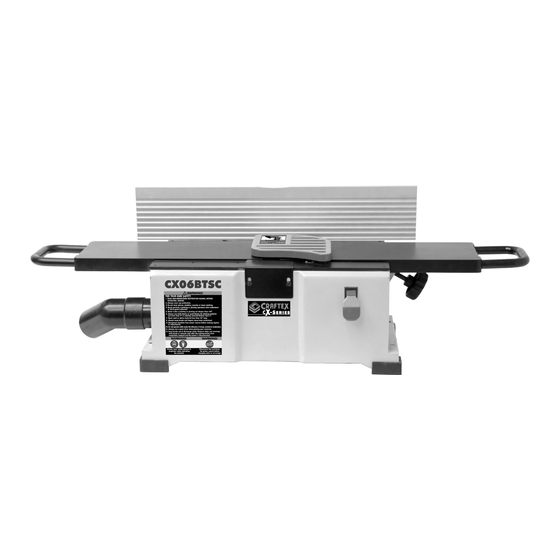
- Page 1 MODEL CX06BTSC 6" BENCHTOP JOINTER w / SPIRAL CUTTERHEAD USER MANUAL...
-
Page 2: Table Of Contents
TABLE OF CONTENTS General Safety Instructions......................3 Specific Safety Instructions......................4 Features............................5 Identification...........................7 Components and Controls......................8 Plug and Grounding Requirements....................10 Unpacking.............................12 Inventory List..........................13 Cleaning Up Your Machine......................14 Bench Mounting & Assembly......................15 Test Run............................17 General Operation.........................18 Material Inspection........................19 Setting the Fence Stops........................20 Adjusting and Setting Depth of Cut....................23 Maintenance..........................28 Lubrication.............................29... -
Page 3: General Safety Instructions
GENERAL SAFETY INSTRUCTIONS Extreme caution should be used when operating all power tools. Know your power tool, be familiar with its operation, read through the owner’s manual and practice safe usage procedures at all times ALWAYS read and understand the user man- NEVER leave a tool unattended while it is in ual before operating the machine. -
Page 4: Specific Safety Instructions
JOINTER SPECIFIC SAFETY INSTRUCTIONS ALWAYS make sure the machine is level be- DO NOT force the work-piece into the cutter- fore operating. head. Feed the stock smoothly using push blocks IF YOU ARE NOT FAMILIAR with the opera- tions of a jointer, you should obtain the ALWAYS inspect your stock before feeding advice and/or instructions from a qualified pro- over the cutter head. -
Page 5: Features
MODEL CX06BTSC 6” BENCHTOP JOINTER WITH SPIRAL CUTTERHEAD Main Specifications: Jointer Size:………………….....……….………………….…………..……………..6” Maximum Cut Width:…………………………………………......…..…..…….…..6” Minimum Material Thickness:………………………………......…....……….. 1/2” Minimum Material Length: …………...…………….......……………………………..8” Bevel Jointing:....................0°- 45°Left And Right Cuts Per Minute:……………............…………….………………24, 000 Electrical Specifications: Hydro Requirement:………......……………….…………...…120V Single Phase 60 Hz Minimum Circuit Size:…………......…………….…………........15A Full Load Current:……………..........…………………………….……12A Connection Type:……………........…………………………….6ft Cord and Plug... - Page 6 Cutter Head Diameter:…………………......………………....…………….1-7/8” Cutter Spirals:………………………………..…......………………………………3 Indexable Cutter Inserts:…………..…………........……………………...…...18 Cutter Head Speed:………………................8000 RPM Insert Type:…………………….................Indexable Carbide Insert Dimensions:……………....……......……..…..15mm x 15mm Insert Thickness:…………………………………….............…….2.5mm Jointer Fence Specifications Length:………………...…………………..............…….22-1/2” Width:………………………….............…………………………….13/16” Height:…………………………..................4-5/16” Thicknes.…………………………….................……...1” Set Fence Stops:.................……… 45°, 90°, and 135° Machine Construction Table:………………………………….………..........………….….Aluminum Body:……………………………….....…......………...…Pre-formed Steel Cutter Head:………………………..............………………….Steel Guard:………………………………......………………......…..Aluminum...
-
Page 7: Identification
Identification WARNING! Read instruction manual before operating jointer for your own safety. 1, Always wear proper personal protection equipment such as hearing and eye protection. 2, Always keep all safety guards in place while operating machine. 3, Always use provided push blocks while jointing materials narrower then 3” or surface planing material thinner than 3”. -
Page 8: Components And Controls
Components and Controls: A. Main On/Off Switch: Turns motor on when D. Fence: Supports material laterally as it in the up position and turns motor off when passes over the cutterhead. The angle of in the down position. the fence determines angle of cut when edge or bevel joining. - Page 9 G. Cutterhead Spring Guard: This sits overtop I. 45° inward Fence Stop: Stops fence at a the cutterhead and moves out of the way 45° inward angle for bevel cuts. when material pushes against it as it passes over the cutterhead during operation. Once J.
- Page 10 POWER SUPPLY AVAILABILITY OF POWER CIRCUIT REQUIREMENTS FOR CX06BTSC Before Installation of this machine you will 6” BENCHTOP JOINTER need to consider the proximity of your power supply circuit. If available circuits do not meet The CX06BTSC has been prewired at the factory the requirements for this machine you will for operation on an electrical circuit that has a veri- have to get a new circuit installed by a licensed...
-
Page 11: Plug And Grounding Requirements
PLUG AND GROUNDING REQUIREMENTS This machine must be grounded so that in the event of certain malfunctions it will reduce NOTE the chances of electrical shock by providing If ever you notice damage or wear to ei- a path of lesser resistance for the electric ther the cord or plug disconnect it imme- current to travel through. -
Page 12: Unpacking
UNPACKING UNPACKING OF THE CX06BTSC This machine has been carefully packed in order to protect it during transport. While un- packing thoroughly go through the box and separate all items from the materials used for packaging. It is always wise to inspect all items for shipping damage. -
Page 13: Inventory List
INVENTORY LIST The following is an itemized list of the items that come with your new machine. Before you begin following the procedures for setup of the machine lay out everything and check that it matches the inventory list. Jointer……………………...….x1 Fence………………………………...x1 Fence Carriage Lock Lever….…….x1 Fence Tilt Lock Lever……………...x1... -
Page 14: Cleaning Up Your Machine
CLEANING UP YOUR MACHINE Your machine has unpainted surfaces that have been covered with a heavy coat of NOTE packing grease and rust preventatives to Avoid using acetone or chlorine based solvents as they will damage painted surfaces. prevent any corrosion during storage or shipment of this machine. -
Page 15: Bench Mounting & Assembly
BENCH MOUNTING P lace the locking plat e ass e mb l y On the base of the machine are mounting holes that allow for the machine to be fas- into the carriage support so that the tened to a workbench to prevent machine locking plate pins are against bottom edge of carriage support. - Page 16 To attach the fence bracket assembly To install the fence tilt lock thread the you will require (2) M6-1 x 20 cap screws handle shaft into the bracket assembly. and (2) 6mm lock washers. Plate Carefully s l i d e t h e f e n c e b r a c k e t Push the fence forward until it makes assembly onto dovetail supports and contact with the cutterhead safety...
-
Page 17: Test Run
To lock the fence into place you must tighten the fence carriage locking lever. To attach the handles to the infeed/ outfeed tables you will require (2) M6-1 x 20 cap screws, (2) 6mm lock washers, and (2) 6mm flat washers. TEST RUN Now that you have completed the assembly of your machine it is time for the test run. -
Page 18: General Operation
HOW TO TEST RUN TENSIONING DRIVE BELT THE MACHINE Please make sure that you have read The last step in the setup of your jointer is and understand all safety instructions tensioning the drive belt. This should be located at the start of the manual. done after approximately the first 16 hours of use. -
Page 19: Material Inspection
To complete a basic operation, the operator will do the following: Put on all required safety equipment l i k e s a f e t y g l a s s e s , e a r p l u g s , and respirator. -
Page 20: Setting The Fence Stops
SETTING THE FENCE STOPS Do not surface plane material containing Setting Fence Stop 90° big or loose knots. Knots when loose run the risk of dislodging and coming out during the Make sure that the machine has been jointing/planing process causing kickbacks, disconnected from its power source. - Page 21 Adjust the fence until it makes contact If fe nce i s n o t a t 9 0 ° w h e n m a k i n g with the machinists square to ensure c on tac t w i t h l i m i t b l o c k r e t u r n t h e accuracy.
- Page 22 Adjust th e inwar d s top bo lt u n til it If the fence tilts away from the table contacts the fence face at 45° inward at 135° outward the stop is set correctly. then tighten the jam nut (where bolt Put the limit block back in place and contacts the bracket assembly).
-
Page 23: Adjusting And Setting Depth Of Cut
ADJUSTING AND SETTING DEPTH OF CUT Depth of Cut Depth of cut on a jointer refers to the amount of material removed from the board face as it passes over the cutterhead. The depth of cut can be set by adjusting the height of the infeed table in relation to the cutterhead inserts at top dead centre and the outfeed table. - Page 24 Loosen tension hex nut and adjust Open the bottom cabinet access panel the set screw for zero stop until it to gain access to the cutterhead pulley. makes contact with table base. Turn the cutterhead pulley to gain access To secure the new table height setting to inserts in need of replacement or tighten the tension hex nut.
- Page 25 Replace or rotate insert so that the sharp edge is facing outward. Make sure that the insert is seated properly before securing into place Before securing insert apply some lubrication (light machine oil) to torx screw threads. Wipe away the excessive lubricant and torque screw to 50 inch/ pounds.
- Page 26 EDGE JOINTING NOTE F o r stability of your work piece ensure that any concave sides are facing in the direction of the jointer table and fence. Thi s pro cess is used to pro duce a p e r - fect ly f lat and true surf ace a lo n g t h e edge of t he ma teri al by removi n g a n y uneven spot s.
- Page 27 EDGE JOINTING NOTE A lways keep hands a mi nimum of 4 ” away f rom t he cutt erhead duri n g o p - Check the stock to make sure that erat ion. Never allo w your hand s t o its suitable for this operation.
-
Page 28: Maintenance
MAINTENANCE BEVEL CUTTING Check the material to determine if WARNING! it’s suitable for this operation. To reduce and avoid any risks such as Set the cutting depth by adjusting shock or even accidental start up of the the height of the infeed table. The machine always make sure that machine adjustment would typically be set is disconnected from its power supply be-... -
Page 29: Lubrication
Monthly C h e c k m o t o r d r i v e b e l t f o r a n y damage, wear, and proper tension. Th ere s hould b e ¼ ” de flec tio n in LEAD dri ve b elt when p re ss ed betw e e n SCREW... - Page 30 Replacing or Adjusting Drive Belt Tension T h e CX 0 6B TSC cu tter he ad b e lt To re move t ension fr om th e d r i v e bel t loosen the 4 mot or sc r e w s . dr i v e n alo ng w it h the d ust co llec tio n Do no t take th em o ut! fa n .
- Page 31 Changing Motor Brushes Re p l a c e t h e m o t o r c o v e r a n d return machine back to its proper upright position for test run. Repeat the Make sure t hat t he machin e ha s belt alignment and tensioning steps been disconnected from its power supply.
- Page 32 Measure each of the carbon b r u sh e s Adjusting Infeed Table for Parallelism fo r w ear using a r u le r. If br ush e s measure less the 3/32” due to wear Make sure t hat t he machin e ha s replace the brushes.
- Page 33 Before turning the machine upside In order to secure the new adjustments d ow n to rem ov e th e mo tor c ov e r ret ight en the cap screws b e f o r e plate identify the highest and lowest restoring the machine to its upright c orne r of t he in feed table.
-
Page 41: Warranty
Proof of purchase is necessary. All warranty claims are subject to inspection of such products or part thereof and Craftex reserves the right to inspect any returned item before a refund or replacement may be issued. This warranty shall not apply to consumable products such as blades, bits, belts, cutters, chisels, punches etceteras.
Need help?
Do you have a question about the CX series and is the answer not in the manual?
Questions and answers