Craftex CX Series Manual
6”×9” belt disc sander
Hide thumbs
Also See for CX Series:
- User manual (49 pages) ,
- Manual (42 pages) ,
- Owner's manual (35 pages)
Table of Contents
Advertisement
Advertisement
Table of Contents

Subscribe to Our Youtube Channel
Related Manuals for Craftex CX Series


Summary of Contents for Craftex CX Series
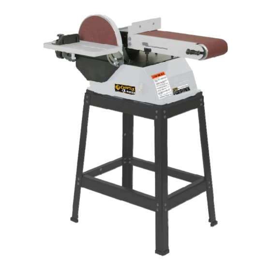
- Page 1 MODEL CX512 6”×9” BELT DISC SANDER...
-
Page 2: Table Of Contents
TABLE OF CONTENTS General Safety Instructions ..................3 CX512 Manual ......................4 Safety Precautions and Specification..............5 Assembly......................... 5 Installing Sanding Belt Fences................6 Installing the Disc Table ..................6 PSA Sandpaper Disc Install ..................7 Adjusting Disc Table Angle ..................8 Adjusting the Belt Assembly.................. -
Page 3: General Safety Instructions
GENERAL SAFETY INSTRUCTIONS Extreme caution should be used when operating all power tools. Know your power tool, be familiar with its operation, read through the owner’s manual and practice safe usage procedures at all times. ALWAYS read and understand the user bits, shaper heads, blades, knives or manual before operating the machine. -
Page 4: Cx512 Manual
CX512 MANUAL GETTING STARTED exposed metal surfaces with a light coating of oil. WARNING CAUTION Be careful not to touch overhead power Never use highly volatile solvents. Avoid lines, piping, lighting, etc. if lifting getting cleaning solutions on paint as it equipment used. -
Page 5: Safety Precautions And Specification
All tools should be visually inspected for loose, missing or damaged parts. Shipping claims must be filed with before use, in addition to regular the carrier. periodic maintenance inspections. Be sure that the voltage label on the Proper electrical receptacle should unit matches your power supply. -
Page 6: Installing Sanding Belt Fences
on their threaded ends. (Washers shown in Figure 3 are optional, not included with the sander). 3. Slide the large fence’s two screws with knobs over the two slots in the small fence and fasten it in place. Figure 1 – Install Foot Pads Depending upon the material being sanded, the fence can easily be Installing the Sanding Belt Fences... -
Page 7: Psa Sandpaper Disc Install
Adjust worktable to level or any angle in NOTE: The 6” x 9” Belt Disc Sander only between 0 degrees and 45 degrees for uses 9” diameter abrasive sanding discs sanding. with Pressure Sensitive Adhesive (PSA) backing. To apply the sandpaper: NOTE: 1. -
Page 8: Adjusting Disc Table Angle
Make sure there is plenty of room for Ensure the sander is disconnected from the moving the workpiece. There must be power source prior to commencing work. enough room that neither operators nor 1. To check the trueness of the 90 Deg. bystanders will have to stand in line with Angle of the disc sanding table, the wood while using the tool. -
Page 9: Adjusting The Belt Assembly
table edge should be set to a maximum of 3. In the horizontal position, there are 1/16 inches away from the sanding two vertical padded set screws that surface. See Figure 9. support the sanding belt frame. These should be checked and adjusted, if necessary, to make sure they both touch the sanding belt frame supports. -
Page 10: Grounding Instructions
switch. Remove the key to prevent or breakdown, grounding provides a path of unauthorized use. least resistance for electrical shock. WARNING Grounding Instructions Do not permit fingers to touch the WARNING terminals of the plug when installing or Improper connection of equipment removing from the outlet. -
Page 11: Extension Cord Length
Wires of the extension cord must be CAUTION of sufficient size to carry the current Always observe the following safety and maintain adequate voltage. precautions: Use the table to determine the minimum wire size (A.W.G.) Whenever adjusting or replacing any extension cord parts on the tool, Turn switch off ... -
Page 12: On/Off Switch
with the belt and with table when keep fingers away from abrasive sanding with disc. belt. Never push a sharp corner of the Use table to position and secure work being sanded. Keep the end workpiece against belt or disc. butted against the table and move Abrasive backing may tear. -
Page 13: Replacing The Sanding Belt
Move workpiece across downside 4. Remove the old belt by sliding it off to the left of the frame. Place the (left) of the abrasive disc. Hold new sanding belt over the drums workpiece firmly with both hands; with the direction arrow pointing in keep fingers away from abrasive the proper direction. -
Page 14: Belt Tracking Adjustment
Belt Tracking Adjustment 1. Peel the abrasive disc from the metal disc plate. A putty knife may Refer to Figure 18. help in this process. 2. Make sure the disc plate is clean of 1. Belt tracking on the center of the any residue. - Page 15 Keep the drums clean. Dirt on the repair is done by a qualified technician. drums will cause poor tracking and belt slippage. Operate the tool with a dust collector to keep dust from accumulating. Be certain the motor is kept clean and is frequently vacuumed free of dust.
-
Page 16: Trouble Shooting Guide For Cx512
Trouble Shooting Guide for CX512 Problem Possible Cause Solution Motor will not start 1. Faulty or defective switch 1. Replace switch 2. Faulty or blown capacitor 2. Replace the capacitor 3. Blown fuse or tripped circuit 3. If fuse is blown replace it with breaker required size. - Page 17 Machine slows down during 1. Applying to much pressure to 1. Ease up on pressure and let the operation workpiece machine do the work 2. V-belt (drive belt is slipping 2. Adjust and increase the V-belt tension Motor stalls (resulting in a 1.
-
Page 19: Parts List For Cx512
Parts List For CX512 Part Number Description Quantity 1 Phillips screw + flat washer M4x6 2 Phillips screw + spring washer + flat washer M4x8 4 3 Base Plate 1 4 Phillips screw M5x8 4 5 Lock handle 2 6 Power cord 1 7 Dust hose 1 8 V‐belt A580 1 9 Hex screw M6x8 5 10 Cord clip 6P4 1 11 Key A5X15 2 12 ... -
Page 20: Parts List For Cx512-2
24 Driving shaft 1 25 Supporting plate 1 26 Hex screw + spring washer + flat washer M8X30 2 27 Hex screw M8X16 4 28 Base 1 29 Rubber foot 4 30 Phillips screw M5X12 1 31 Capacitor bracket 1 32 Hex nut, I type M5 3 33 Phillips screw M4X10 11 34 Hex screw + spring washer + flat washer M6x12 4 35 Capacitor 20UF/120V 1 36 Capacitor 20UF/300V 1 37 Capacitor bracket ... -
Page 21: Parts List For Cx512-3
49 Hex screw M8x30 3 50 Hex screw M5x30 1 51 Supporting plate 2 52 Platen 1 53 Sanding belt (6” x 48” 120 grit) 1 54 Phillips screw M6x14 2 55 Fence 1 56 Fence Support 1 57 Locking nut 2 58 Flat Washer M8 5 59 Rubber foot 2 60 Dust port cover 1 61 Phillips screw + spring washer M5x16 3 62 Tensioning Spring ... -
Page 22: Parts List For Cx512-4
74 Inner hex position screw M5x6 2 75 Spring washer for shaft M12 2 76 Driven shaft 1 77 Driven drum 1 78 Miter gauge knob 2 79 Miter gauge label 1 80 Miter gauge 1 81 Phillips screw + spring washer + flat washer M5x8 1 82 Phillips screw M8x25 2 83 Slide bar 1 84 Miter gauge pointer 1 85 Disc table left support 1 86 Left scale 1 87 Right scale ... -
Page 23: Parts List For Cx512-5
99 Disc cover 1 100 Adapter 1 101 Pointer 2 102 Hex wrench S=4 1 103 Hex wrench 1 104 Clip 1 105 Hex nut M5 2 106 Phillips screw M5x10 2 107 Hex nut M6 4 108 Phillips screw + outer tooth washer + flat washer M5x16 1 ... -
Page 24: Warranty
CRAFTEX 3 YEARS LIMITED WARRANTY Craftex warrants every product to be free from defects in materials and agrees to correct such defects where applicable. This warranty covers three years for parts and 90 days for labour (unless specified otherwise), to the original purchaser from the date of purchase but does not apply to malfunctions arising directly or indirectly from misuse, abuse, improper installation or assembly, negligence, accidents, repairs or alterations or lack of maintenance.
Need help?
Do you have a question about the CX Series and is the answer not in the manual?
Questions and answers