DFI KS070-AL User Manual
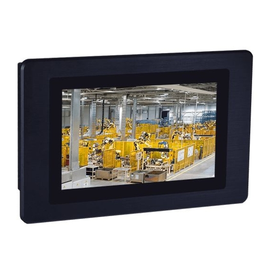
7” touch panel pc
Hide thumbs
Also See for KS070-AL:
- Installation manual (12 pages) ,
- Installation manual (19 pages) ,
- Installation manual (12 pages)
Table of Contents
Advertisement
Quick Links
Download this manual
See also:
Installation Manual
Advertisement
Table of Contents

Related Manuals for DFI KS070-AL


Summary of Contents for DFI KS070-AL
- Page 1 KS070-AL 7” Touch Panel PC User’s Manual A48200809 Chapter 1 Introduction www.dfi.com...
-
Page 2: Copyright
Product names or trademarks appearing in this manual are for identification purpose only and Shielded interface cables must be used in order to comply with the emission limits. are the properties of the respective owners. Chapter 1 Introduction www.dfi.com... -
Page 3: Table Of Contents
Panel Mount ................30 Key Features ................6 Specifications ................7 Chapter 7 - BIOS Setup ............32 Getting to Know the KS070-AL ..........8 Mechanical Dimensions ............9 Chapter 8 - Supported Software ........44 Chapter 2 - Getting Started ..........10 Chapter 3 - Installing Devices ..........11 Removing the Chassis Cover ........... -
Page 4: About This Manual
After installation or servicing, cover the system chassis before plugging the power cord. Battery: • Danger of explosion if battery incorrectly replaced. • Replace only with the same or equivalent type recommend by the manufacturer. • Dispose of used batteries according to local ordinance. Chapter 1 Introduction www.dfi.com... -
Page 5: Safety Precautions
• Disconnect the system from the DC outlet before cleaning. Use a damp cloth. Do not use liquid or spray detergents for cleaning. Chapter 1 Introduction www.dfi.com... -
Page 6: Chapter 1 - Introduction
Chapter 1 Chapter 1 - Introduction Key Features Overview Model Name KS070-AL KS070-AL Processor Intel Atom ® Processor E3900 Series, BGA 1296 Intel Atom ® x5-E3940 Processor, Quad Core, 2M Cache, 1.6GHz (1.8GHz), 9.5W Intel ® Celeron ® Processor N3350, Dual Core, 2M Cache, 1.1GHz (2.4GHz), 6W... -
Page 7: Specifications
System Reset, Programmable via Software from 1 to 255 Seconds Power Type:12V DC Note: Connector: DC Jack *Optional items are not supported in standard model. Please contact your sales repre- OS Support Windows 10 IoT Enterprise 64-bit sentative for more information. (UEFI only) Chapter 1 Introduction www.dfi.com... -
Page 8: Getting To Know The Ks070-Al
Chapter 1 Getting to Know the KS070-AL Top View Bottom View COM 2 DC-in Power button (RS232/RS422/RS485) Mic-in VGA USB 2.0 LAN 2 LAN 1 DP++ Line-out USB 3.0 Antenna holes COM 1 (RS232/RS422/RS485) Power Button COM Ports Press to power on or power off the system. -
Page 9: Mechanical Dimensions
Chapter 1 Mechanical Dimensions Top View Right View Front View 208.50 50.80 Left View 7.50 Bottom View Chapter 1 Introduction www.dfi.com... -
Page 10: Chapter 2 - Getting Started
Installing the Drivers The system package includes a CD disk. The CD includes drivers that must be installed to pro- vide the best system performance. Refer to the Supported Software chapter for instructions on installing the drivers. Chapter 2 Getting Started www.dfi.com... -
Page 11: Chapter 3 - Installing Devices
Do not force the card into the slot if the card is not correctly inserted. Close the CFast card cover and attach the screw. To eject the card, push the card inward to release the lock and pull it out. CFast slot cover Chapter 3 Installing Devices www.dfi.com... -
Page 12: Removing The Chassis Cover
Remove these screws and put them in a safe place for later use. Mini PCIe socket M.2 socket Mounting screw Mounting screw Mounting screw Lift the cover up to open the system. Lift the cover upward Chapter 3 Installing Devices www.dfi.com... -
Page 13: Installing An M.2 Card
SATA and PCIe, refer to Chapter 4. Insert the M.2 card into the connector. M.2 card Push down on the other end of the M.2 card and secure and card on the mainboard with the provided mounting screw. Mounting screw Chapter 3 Installing Devices www.dfi.com... - Page 14 Mini PCIe card Push the Mini PCIe card down and use the provided mounting screws to secure the card on the system board. Mounting screw Chapter 3 Installing Devices www.dfi.com...
-
Page 15: Chapter 4 - Jumper Settings
2. Set the jumper pins 2 and 3 to On. Wait for a few seconds and set the jumper back to its default setting, pins 1 and 2 On. 3. Now plug the power cord and power on the system. www.dfi.com Chapter 4 Jumper Settings... -
Page 16: Auto Power-On Select
When using the JP7 “Power On” feature to power the system back on after a power failure, the system may not power on if the power loss is resumed within 5 seconds (i.e., power flicker). www.dfi.com Chapter 4 Jumper Settings... -
Page 17: Backlight Power Select
Before powering on the system, make sure that the power settings of JP12 match power specification of backlight control. Selecting the incorrect voltage will seriously the LCD panel’s specification. Selecting the incorrect voltage will seriously damage the damage the backlight. LCD panel. www.dfi.com Chapter 4 Jumper Settings... -
Page 18: Lcd/Inverter Power Select
Panel Power Select (JP12) SPI Flash BIOS Front COM 1-2 Panel SATA 3.0 SATA 0 Buzzer SATA Power DP++ USB3.0 Type C JP11 is used to select the power level of the LCD/inverter power connector. www.dfi.com Chapter 4 Jumper Settings... -
Page 19: Chapter 5 - Ports And Connectors
Chapter 5 Chapter 5 - Ports and Connectors Top Panel I/O Ports Bottom Panel I/O Ports COM 2 DC-in Power button (RS232/RS422/RS485) Mic-in VGA USB 2.0 LAN 2 LAN 1 DP++ Line-out USB 3.0 Antenna holes COM 1 (RS232/RS422/RS485) The top panel I/O consists of the following ports and connectors: The bottom panel I/O consists of the following ports and connectors: •... -
Page 20: Usb Ports
Chapter 5 USB Ports Driver Installation You may need to install the proper drivers in your operating system to use USB devices. Refer to Chapter 8 for more information. Wake-On-USB Keyboard/Mouse DC-in SPK-OUT The Wake-On-USB Keyboard/Mouse function allows you to use a USB keyboard or USB mouse EIO (optional) DC-in to wake up a system from the S3 (STR - Suspend To RAM) state. -
Page 21: Com (Serial) Ports
Chapter 5 COM (Serial) Ports COM Port Connector COM 1 (RS232/422/485) / COM 2 (RS232/422/485) DC-in SPK-OUT 1 2 3 4 5 1 2 3 4 5 EIO (optional) 1 2 3 4 5 DC-in DC-in Digital I/O SMBus Front Audio Intel WGI211AT LAN 1... -
Page 22: Graphics Interfaces
Chapter 5 Graphics Interfaces Audio Output SPK Out L+ SPK Out L- Speaker Out SPK Out R- (Optional) The display ports consist of the following: SPK Out R+ DC-in SPK-OUT EIO (optional) • 1 VGA port DC-in DC-in Digital I/O •... -
Page 23: Dc-In Power Connector
Chapter 5 DC-in Power Connector RJ45 LAN Ports DC-in DC-in SPK-OUT EIO (optional) SPK-OUT EIO (optional) DC-in DC-in DC-in DC-in Digital I/O Digital I/O SMBus Front Audio SMBus Intel Front Audio WGI211AT Intel LAN 1 WGI211AT LAN 1 (JP1) (JP11) 9 10 (JP1) (JP11) -
Page 24: I/O Connectors
Chapter 5 I/O Connectors USB OTG Connector Serial ATA Connector & Serial ATA Power Connector DC-in DC-in SPK-OUT EIO (optional) DC-in SPK-OUT DC-in EIO (optional) Digital I/O DC-in DC-in Digital I/O SMBus Front Audio Intel SMBus WGI211AT LAN 1 Front Audio Intel WGI211AT LAN 1... -
Page 25: Lvds Lcd Panel & Inverter Power Connector
Chapter 5 LVDS LCD Panel & Inverter Power Connector LVDS LCD Panel Connector LCD/Inverter Power Connector Pins Function Pins Function Pins Function DC-in SPK-OUT EIO (optional) DC-in DC-in Digital I/O SMBus LVDS_Out3+ (Odd_3+) LVDS_Out7+ (Even_3+) Front Audio Intel WGI211AT LAN 1 Dimming Control LVDS_Out3- (Odd_3-) LVDS_Out7- (Even_3-) -
Page 26: Digital I/O Connector
Chapter 5 Digital I/O Connector Expansion Slots DC-in Digital I/O SPK-OUT EIO (optional) DC-in DC-in Digital I/O DC-in Digital I/O SPK-OUT EIO (optional) DC-in SMBus DC-in Front Audio Digital I/O Intel WGI211AT LAN 1 SMBus Front Audio (JP1) Intel (JP11) 9 10 WGI211AT LAN 1... -
Page 27: Front Panel Connector
Chapter 5 Front Panel Connector Standby Power LED DC-in SPK-OUT DC-in EIO (optional) DC-in DC-in SPK-OUT Digital I/O EIO (optional) DC-in DC-in Digital I/O SMBus Front Audio Intel WGI211AT LAN 1 SMBus Front Audio Intel WGI211AT LAN 1 (JP1) (JP11) 9 10 Intel USB 2.0... -
Page 28: Battery
Chapter 5 Battery SMBus Connector DC-in DC-in SPK-OUT EIO (optional) SPK-OUT EIO (optional) DC-in DC-in DC-in DC-in Digital I/O Digital I/O SMBus SMBus SMBus Front Audio Intel Front Audio Intel WGI211AT LAN 1 WGI211AT LAN 1 (JP1) (JP11) 9 10 (JP1) (JP11) 9 10... -
Page 29: Chapter 6 - Mounting Options
Attach the other bracket (wall mount bracket 2) to the rear of the Panel PC. Wall mount bracket 1 Wall mount bracket 2 Mounting screw Before starting any installation procedure, attach the poron foam to the Panel PC. Wall mount bracket 2 Hooks Poron foam Chapter 6 Mounting Options www.dfi.com... -
Page 30: Panel Mount
Cut out a shape on the panel that corresponds to the Panel PC’s rear dimensions (210.5mm x 132.2mm) and ensure that the Panel PC can be fitted into the panel properly. Mounting hole Panel 210.50 Chapter 6 Mounting Options www.dfi.com... - Page 31 Tighten the clamp’s screw using an electric screwdriver by pressing the white plastic cap onto the back of the panel. The illustration below shows that all clamps are properly mounted. 210.50 Chapter 6 Mounting Options www.dfi.com...
-
Page 32: Chapter 7 - Bios Setup
To display the submenu, move the highlight to disappears before you respond, restart the system or press the “Reset” button. You may also that field and press <Enter>. restart the system by pressing the <Ctrl> <Alt> and <Del> keys simultaneously. Chapter 7 BIOS Setup www.dfi.com... - Page 33 23. Minute displays minutes from 00 to 59. Second displays seconds from 00 to 59. System Date The date format is <month>, <date>, <year>. Month displays the month, from Janu- ary to December. Date displays the date, from 1 to 31. Year displays the year, from 1980 to 2099. Chapter 7 BIOS Setup www.dfi.com...
- Page 34 Enable or disable the display of an operating system logo or image during boot using the BGRT (Boot Graphics Resource Table) mechanism. Enable or disable CPU power management. It allows the CPU to go to C states when it’s not 100% utilized. Chapter 7 BIOS Setup www.dfi.com...
- Page 35 Select the type of LCD panel connected to the system’s LCD connector. Please check the specification of your LCD monitor. Panel Color Depth Select the LCD panel color depth: 18 bit, 24 bit, 36 bit, and 48 bit. Chapter 7 BIOS Setup www.dfi.com...
- Page 36 Enable or disable each Serial ATA port and its hot plug function. SATA Port 0: It controls the signal of the CFast card slot. SATA Port 1: It controls the signal of the M.2 slot. SATA Controller Enable or disable the Serial ATA controller. Chapter 7 BIOS Setup www.dfi.com...
- Page 37 Controls the PCIe signal of LAN Port 2. PCI Express Root Port 5 Controls the PCIe signal of Mini PCIe slot. Press “Enter” to enter the configurations for each PCIe root port as shown on the next page. Chapter 7 BIOS Setup www.dfi.com...
- Page 38 Select the speed of the PCI Express Root Port: Auto, Gen1 (2.5 GT/s) or Gen2 (5 GT/s). Parity: None, Even or Odd. Stop bits: 1 bit or 2 bits. Flow control: None, RTS/CTS or XON/XOFF This is the global setting for all of the designated serial ports for console redirection. Chapter 7 BIOS Setup www.dfi.com...
- Page 39 Choose RS232, RS422 or RS485 (Peer-to-Peer) for the serial port type for COM port 1 and 2. Enable or disable the watchdog function. A counter will appear if you select to enable WDT. Input any value between 1 and 255. Chapter 7 BIOS Setup www.dfi.com...
- Page 40 Set the administrative password for entering the BIOS utility or upon the entering of the power-on self-test (POST) process. The length of the password must be greater than 1 character and less than or equal to 10 characters. Chapter 7 BIOS Setup www.dfi.com...
- Page 41 Enable or disable Preboot eXecution Environment (PXE) boot through the Ethernet. This function can only be enabled if the Network Stack support is enabled. USB Boot Enable or disable USB boot from a flash drive. Chapter 7 BIOS Setup www.dfi.com...
- Page 42 DSF file extension and can be used for restoration. Restore Setting from file Select this option to restore BIOS configuration settings from a USB drive. Note that this option will not be available if there aren’t any USB devices detected on the system. Chapter 7 BIOS Setup www.dfi.com...
- Page 43 Copyright(c) 2012 - 2016, Insyde Software Corp. All Rights Reserved. Initializing Current BIOS Model name: AL551 New BIOS Model name: AL551 Current BIOS version: 68.08A New BIOS version: 68.08A Updating Block at FFFFF000h 100% 100% C:\SU25x>_ Chapter 7 BIOS Setup www.dfi.com...
-
Page 44: Chapter 8 - Supported Software
Chapter 8 Chapter 8 - Supported Software The CD that came with the system board contains drivers, utilities and software applications required to enhance the performance of the system board. Insert the CD into a CD-ROM drive. The auto-run screen (the Utility and Manual CD) will ap- pear. - Page 45 Chapter 8 Intel Chipset Software Installation Utility 3. Go through the readme docu- ment for more installation tips then click “Install.” The Intel Chipset Device Software is used for updating Windows INF files so that the Intel ® chipset can be recognized and configured properly in the system. To install the utility, click “Intel Chipset Software Installation Utility”...
- Page 46 Chapter 8 Intel Graphics Drivers 3. Go through the Readme docu- ment for system requirements and installation tips, then click To install the driver, click “Intel Graphics Drivers” in the main menu. “Next”. 1. Setup is now ready to install the graphics driver.
- Page 47 Chapter 8 Intel LAN Drivers 4. Click “Install” to begin the installation. To install the driver, click “LAN Drivers” in the main menu. 1. Setup is ready to install the driver. Click “Next” to continue. 5. After the installation is complete, click “Finish”...
- Page 48 Chapter 8 Intel Trusted Execution Engine Driver To install the driver, click “Intel TXE Drivers” in the main menu. 1. Select “I accept the terms 3. The screen displays the in the License Agreement”, installation status in then click “Next.” progress.
- Page 49 Chapter 8 Realtek Audio Drivers IO Driver To install the driver, click “Realtek Audio Drivers” in the main menu To install the Intel Serial IO driver, click “IO Driver” in the main menu. ® 1. Setup is now ready to install the 1.
- Page 50 Chapter 8 Read the file information for instal- Setup is now installing the driver. lation information, then click “Next”. 4. Setup is ready to install the driver. Click “Finish” to exit setup. Click “Next” to begin the installation. Chapter 4 Supported Software...
- Page 51 Chapter 8 eGalaxTouch Touch Panel Driver To install this driver, click “eGalaxTouch Touch Screen Driver” in the main menu. 1. Setup is ready to install the driver. 3. Setup detects that an extra RS232 interface driver needs to Click “Next” to continue. be installed for the eGalaxTouch controller.
- Page 52 Chapter 8 Wi-Fi Driver 5. Select whether to support the multi-monitor system. To install the Wi-Fi driver, click “WLAN Driver” in the main menu. 1. Select the language for the instal- lation. 6. Select the installation folder. Follow the rest of the steps on the screen to complete the installation proce- dure.
- Page 53 Chapter 8 3. Read the license agreement care- fully. Click “I accept the terms of the license agreement” if you agree with the terms in the agreement, then click "Next”. 4. Click “Finish” to exit the installation wizard. Chapter 4 Supported Software...
Need help?
Do you have a question about the KS070-AL and is the answer not in the manual?
Questions and answers