Table of Contents
Advertisement
Quick Links
Download this manual
See also:
Installation Manual
Advertisement
Table of Contents

Related Manuals for DFI KS070-BT


Summary of Contents for DFI KS070-BT
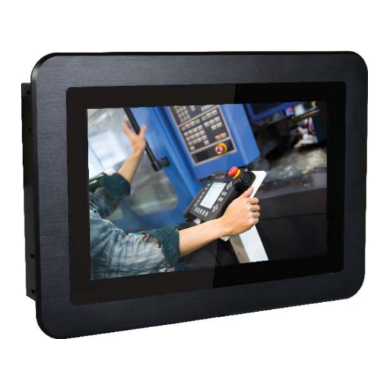
- Page 1 KS070-BT 7” Touch Panel PC User’s Manual A47200736 Chapter 1 Introduction www.dfi.com...
-
Page 2: Copyright
Product names or trademarks appearing in this manual are for identification purpose only and Shielded interface cables must be used in order to comply with the emission limits. are the properties of the respective owners. Chapter 1 Introduction www.dfi.com... -
Page 3: Table Of Contents
Wall Mount ................28 Key Features ................6 Panel Mount ................29 Specifications ................7 Getting to Know the KS070-BT ..........8 Chapter 7 - BIOS Setup ............31 Mechanical Dimensions ............9 Chapter 2 - Getting Started ..........10 Chapter 8 - Supported Software ........44 Appendix A - System Error Message ........55... -
Page 4: About This Manual
After installation or servicing, cover the system chassis before plugging the power cord. Battery: • Danger of explosion if battery incorrectly replaced. • Replace only with the same or equivalent type recommend by the manufacturer. • Dispose of used batteries according to local ordinance. Chapter 1 Introduction www.dfi.com... -
Page 5: Safety Precautions
• Disconnect the system from the DC outlet before cleaning. Use a damp cloth. Do not use liquid or spray detergents for cleaning. Chapter 1 Introduction www.dfi.com... -
Page 6: Chapter 1 - Introduction
Chapter 1 Chapter 1 - Introduction Key Features Overview Model Name KS070-BT KS070-BT Processor Intel Atom™ Processor E3800 Series, BGA 1170 ® Intel Atom™ Processor E3845, Quad Core, 2M Cache, 1.91GHz, 10W ® Intel Celeron Processor J1900, Quad Core, 2M Cache, 2GHz (2.42GHz), 10W ®... -
Page 7: Specifications
*Optional items are not supported in standard model. Please contact your sales repre- 1 x DC-in connector sentative for more information. Watchdog Timer System Reset, Programmable via Software from 1 to 255 Seconds Power Type:12~36V DC Connector: DC Jack Chapter 1 Introduction www.dfi.com... -
Page 8: Getting To Know The Ks070-Bt
Chapter 1 Getting to Know the KS070-BT Top View Bottom View LAN 1 LAN 2 Line-out Mic-in COM 3 Antenna Antenna hole hole COM 4, COM 2, COM 1 USB 3.0 Power DC-in HDMI USB 2.0 Reset/ Status LED Power Button with LED (Green) DC-in Press to power on or power off the system. -
Page 9: Mechanical Dimensions
Chapter 1 Mechanical Dimensions Motherboard Dimensions KS070-BT Top View 113.4 102.93 99.26 105.85 103.35 21.8 19.8 Front View 11.45 Left View 11.8 Right View 9.65 Bottom View Chapter 1 Introduction www.dfi.com... -
Page 10: Chapter 2 - Getting Started
Installing the Drivers The system package includes a CD disk. The CD includes drivers that must be installed to pro- vide the best system performance. Refer to the Supported Software chapter for instructions on installing the drivers. Chapter 2 Getting Started www.dfi.com... -
Page 11: Chapter 3 - Installing Devices
Remove these screws and put them in a safe place for later use. Mini PCIe slot microSD socket Mounting screw Mounting screw Lift the cover up to open the system. Lift the cover upward Chapter 3 Installing Devices www.dfi.com... -
Page 12: Installing A Sata Drive
Align the mounting holes of the HDD drive bay with the mounting holes on the system and and use the provided mounting screws to attach the SATA HDD to the drive bay. use the provided mounting screws to secure the drive bay in place. Mounting screw Mounting screw Chapter 3 Installing Devices www.dfi.com... - Page 13 The system also has one additional full-size Mini PCIe and one half-size Mini PCIe slot The system also has one additional full-size Mini PCIe and one half-size Mini PCIe slot that use the PCIe and LPC interface respectively. that use the mSATA and LPC interface respectively. Chapter 3 Installing Devices www.dfi.com...
-
Page 14: Chapter 4 - Jumper Settings
2. Set jumper pins 2 and 3 to On. Wait for a few seconds and set the jumper back to its de- fault setting, pins 1 and 2 On. 3. Now plug the power cord and power on the system. www.dfi.com Chapter 4 Jumper Settings... -
Page 15: Usb Power Select
LCD panel’s specification. Selecting the incorrect voltage will seriously damage the +5V_standby power source of your power supply must support ≥1.5A. For 3 or more USB ports, the +5V_standby power source of your power supply must support ≥2A. LCD panel. www.dfi.com Chapter 4 Jumper Settings... -
Page 16: Backlight Enable Power Select
You need to refer to your panel’s user guide to determine the type of mode (PWM or power specification of backlight control. Selecting the incorrect voltage will seriously Voltage) that is appropriate for your panel. damage the backlight. www.dfi.com Chapter 4 Jumper Settings... -
Page 17: Digital I/O Power Select
Based on the power level of DIO (Digital I/O) selected on JP17, JP20 (for DIO pin 0-3) and JP18 (for DIO pin 4-7) are used to select the state of DIO output: pull-high or pull-low. When selecting pull-high, the power selection will be set according to JP17’s setting. www.dfi.com Chapter 4 Jumper Settings... -
Page 18: Lcd/Inverter Power Select
The system board uses JP21 and JP22 to select between RS232/422/485 COM 4 or an 8-bit JP2 is used to select the power level of the LCD/inverter power connector. DIO connector. Note: You cannot use COM 4 and DIO at the same time. Please set up JP21 and JP22 together. www.dfi.com Chapter 4 Jumper Settings... -
Page 19: Chapter 5 - Ports And Connectors
Chapter 5 Chapter 5 - Ports and Connectors Top Panel I/O Ports Bottom Panel I/O Ports DC-in HDMI COM 1 COM 2 COM 4 Power button Mic-in USB 2.0 USB 3.0 LAN 2 LAN 1 COM 3 Line-out Reset Button The top panel I/O consists of the following ports and connectors: The bottom panel I/O consists of the following ports and connectors: •... -
Page 20: Usb Ports
Chapter 5 USB Ports Driver Installation You may need to install the proper drivers in your operating system to use the USB device. Refer to Chapter 8 for more information. JP22 (JP20) Wake-On-USB Keyboard/Mouse (JP18) Battery (JP17) (JP22, JP21) COM 4/DIO Select Chassis Intrusion Digital I/O 4-7 Output State... -
Page 21: Com (Serial) Ports
USB 2 Power RS232/RS422/RS485 Select Select (JP6) (JP5) (JP25) (JP2) LAN 2 USB 5 (JP23) (JP3) Model Name KS070-BT (JP4) COM 5 USB 2.0 LVDS LCD HDMI Panel USB 0 (USB 3.0) Native Auto Power-on Select (JP25) LAN 1 LCD/Inverter Power Select (JP2) USB 2 (USB 2.0) -
Page 22: Graphics Interfaces
Chapter 5 Graphics Interfaces COM 1 / COM 2 / COM 3 / COM 4 The system is equipped with an external HDMI port. 1 2 3 4 5 1 2 3 4 5 1 2 3 4 5 JP22 (JP20) (JP18) Battery... -
Page 23: Dc-In Power Connector
Chapter 5 DC-in Power Connector RJ45 LAN Ports JP22 (JP20) JP22 (JP18) Battery (JP20) (JP17) (JP18) Battery COM 4/DIO Select (JP22, JP21) (JP17) Chassis Digital I/O 4-7 Output State (JP18) Intrusion (JP21) (JP22, JP21) COM 4/DIO Select Chassis Digital I/O 0-3 Output State (JP20) Intrusion Digital I/O 4-7 Output State... -
Page 24: Audio Output
Chapter 5 I/O Connectors Audio Output Serial ATA Connector JP22 Serial ATA Power Connector (JP20) (JP18) Battery (JP17) COM 4/DIO Select (JP22, JP21) Chassis Digital I/O 4-7 Output State (JP18) Intrusion (JP21) Digital I/O 0-3 Output State (JP20) Digital I/O Power Select (JP17) Buzzer Clear CMOS... -
Page 25: Lvds Lcd Panel
Chapter 5 LVDS LCD Panel Pins Function Pins Function JP22 (JP20) (JP18) Battery LVDS_Out3+ (Odd_3+) LVDS_Out7+ (Even_3+) (JP17) COM 4/DIO Select (JP22, JP21) Chassis Intrusion Digital I/O 4-7 Output State (JP18) (JP21) Digital I/O 0-3 Output State (JP20) Digital I/O Power Select (JP17) LVDSA_DATA3N (Odd_3-) LVDSB_DATA3N (Even_3-) -
Page 26: Cooling Fan Connector
Chapter 5 Cooling Fan Connector Chassis Intrusion Connector JP22 JP22 (JP20) (JP20) (JP18) (JP18) Chassis Battery Battery (JP17) (JP17) Intrusion Ground COM 4/DIO Select (JP22, JP21) (JP22, JP21) Chassis COM 4/DIO Select Chassis Digital I/O 4-7 Output State (JP18) Intrusion Intrusion Digital I/O 4-7 Output State (JP18) -
Page 27: Expansion Slots
Chapter 5 Expansion Slots Battery Mini PCIe with PCIe, USB microSD socket and LPC signals (optional) Battery Battery JP22 (JP20) Ground (JP18) Battery (JP17) (JP22, JP21) COM 4/DIO Select Chassis JP22 (JP18) Intrusion Digital I/O 4-7 Output State (JP21) (JP20) Digital I/O 0-3 Output State (JP20) (JP18) -
Page 28: Chapter 6 - Mounting Options
Attach the other bracket (wall mount bracket 2) to the rear of the Panel PC. Wall mount bracket 1 Wall mount bracket 2 Before starting any installation procedures, attach the poron foam to the Panel PC. Mounting screw Wall mount bracket 2 Poron foam Hooks Chapter 6 Mounting Options www.dfi.com... -
Page 29: Panel Mount
Select a place on the panel (or wall) where you will mount the Panel PC. Cut out a shape on the panel that corresponds to the Panel PC’s rear dimensions (272mm x 169mm) and ensure that the Panel PC can be fitted into the panel properly. Mounting hole Panel Chapter 6 Mounting Options www.dfi.com... - Page 30 The maximum thickness of your panel’s mounting wall should be 10 mm for secure The system also has one additional full-size Mini PCIe and one half-size Mini PCIe slot panel mount. that use the mSATA and LPC interface respectively. Chapter 6 Mounting Options www.dfi.com...
-
Page 31: Chapter 7 - Bios Setup
To display the submenu, move the highlight to disappears before you respond, restart the system or press the “Reset” button. You may also that field and press <Enter>. restart the system by pressing the <Ctrl> <Alt> and <Del> keys simultaneously. Chapter 7 BIOS Setup www.dfi.com... -
Page 32: Ami Bios Setup Utility
The time format is <hour>, <minute>, <second>. The time is based on the 24-hour military-time clock. For example, 1 p.m. is 13:00:00. Hour displays hours from 00 to 23. Minute displays minutes from 00 to 59. Second displays seconds from 00 to 59. Chapter 7 BIOS Setup www.dfi.com... - Page 33 Change Settings Select the IO and IRQ address for each COM port. COM Driver Mode Set the serial communication mode for each COM port. This option is only available for COM Port 1 to 4. Chapter 7 BIOS Setup www.dfi.com...
- Page 34 Chapter 7 HW Monitor This section shows system health information. Case Open Set this field to “Enabled” to allow the system to alert you of a chassis intrusion event. Chapter 7 BIOS Setup www.dfi.com...
- Page 35 After it Enable or disable hot-plugging for Serial-ATA port 0 and 1. is enabled in the BIOS, you can enable the EIST feature using the operating system’s power management. Chapter 7 BIOS Setup www.dfi.com...
- Page 36 UEFI boot, configure network settings using the “Network Stack Enter the wait time value to abort the PXE boot by pressing the “ESC” key. Configuration” menu. Video Choose to allow the execution of UEFI, Legacy Video Option ROM or none. Chapter 7 BIOS Setup www.dfi.com...
- Page 37 Windows 7 installation. Please refer to the following tables for more information on USB port types. Table 2. The Type of USB Ports Model Name KS070-BT USB 0 (USB 3.0) Native USB 2 (USB 2.0) Native (share with USB 3.0 port) USB 5 (USB 2.0)
- Page 38 Chapter 7 Security Configuration This section configures the Intel Trusted Execution Engine. ® TXE HMRFP0 Select to enable or disable the Intel Trusted Execution Engine. ® Chapter 7 BIOS Setup www.dfi.com...
- Page 39 This section displays the information of the installed memory modules. Select one of the following options to configure: North Bridge The North Bridge shows memory configuration. South Bridge The items in the South Bridge include USB controllers and PCI Express ports. Chapter 7 BIOS Setup www.dfi.com...
- Page 40 This option lets you configure PCI Express root ports. The PCI Express Port 2 controls the full-size Mini PCIe (using PCIe and USB signals) slot. The PCI Express Port 3 controls the half-size Mini PCIe (using PCIe, USB and LPC signals) slot. Chapter 7 BIOS Setup www.dfi.com...
- Page 41 20 characters. This password establishes the BIOS Speed administrative privilege for entering the setup utility. Select the speed for the PCI Express port: Auto, Gen1 (2.5 GT/s) or Gen2 (5 GT/s). Chapter 7 BIOS Setup www.dfi.com...
- Page 42 <Enter>. A dialog box will appear. Select “Yes” to restore the default values of all the setup options. Boot Override Select a boot device below to override a previously defined boot device in the "Boot" menu and boot the system with the selection. Chapter 7 BIOS Setup www.dfi.com...
-
Page 43: Updating The Bios
EEPROM programmer has been burned and follow the Verifying flash ......done technical person's instructions to confirm that the MAC address should be burned Erasing BootBlock ....done Writing BootBlock ....done or not. Verifying BootBlock ....done C:\AFU\AFUDOS> Chapter 7 BIOS Setup www.dfi.com... -
Page 44: Chapter 8 - Supported Software
Chapter 8 Chapter 8 - Supported Software Auto Run Page (For Windows 7) The CD that came with the system board contains drivers, utilities and software applications required to enhance the performance of the system board. Insert the CD into a CD-ROM drive. The auto-run screen (Mainboard Utility CD) will appear. If the “Autorun”... - Page 45 Chapter 8 Intel Chipset Software Installation Utility 3. Go through the readme docu- ment for more installation tips then click “Next”. The Intel Chipset Device Software is used for updating Windows INF files so that the Intel ® chipset can be recognized and configured properly in the system. To install the utility, click “Intel Chipset Software Installation Utility”...
- Page 46 Chapter 8 Intel HD Graphics Drivers 3. Go through the readme docu- ment for system requirements and installation tips then click To install the driver, click “Intel HD Graphics Drivers” in the main menu. “Next”. 1. Setup is now ready to install the graphics driver.
- Page 47 Chapter 8 Intel LAN Drivers 4. Click “Install” to begin the installation. To install the driver, click “LAN Drivers” in the main menu. 1. Setup is ready to install the driver. Click “Next” to continue. 5. After the installation is complete, click “Finish”...
- Page 48 Chapter 8 Kernel Mode Driver Framework (For Windows 7 only) Intel Trusted Execution Engine Driver To install the driver, click “Kernel Mode Driver Framework” in the main menu. To install the driver, click “Intel Trusted Execution Engine Driver” in the main menu. 1.
- Page 49 Chapter 8 Realtek Audio Drivers 3. The screen displays the installation status in progress. To install the driver, click “Realtek Audio Drivers” in the main menu 1. Setup is now ready to install the audio driver. Click “Next”. 2. Follow the on-screen instruc- tions to proceed with the setup program.
- Page 50 Chapter 8 Infineon TPM Driver and Tool (optional) 4. Enter the necessary information and click “Next”. To install the driver, click “Infineon TPM driver and tool (option)” in the main menu. 1. The setup program is preparing to install the driver. 5.
- Page 51 Chapter 8 7. TPM requires installing the Micro- 10. Click “Yes“ to restart your system. soft Visual C++ package prior to installing the utility. Click “Install”. 8. The setup program is currently installing the Microsoft Visual C++ package. 9. Click “Finish” to exit the setup program.
- Page 52 Chapter 8 Intel USB 3.0 Drivers (For Windows 7 Only) 3. Go through the readme docu- ment for more installation tips then click “Next”. To install the driver, click “Intel USB 3.0 Driver” in the main menu. 1. Setup is ready to install the driver. Click “Next”.
- Page 53 Chapter 8 Adobe Acrobat Reader 9.3 To install the reader, click “Adobe Acrobat Reader 9.3” in the main menu. 1. Click “Next” to install or click “Change Destination Folder” to select another folder. 2. Click “Install” to begin the instal- lation.
- Page 54 Chapter 8 Wireless LAN To install the wireless LAN drivers, click “WLAN Driver” in the main menu. 4. Wait while the driver is being 1. The Wizard is preparing the installation files for the Qualcom installed and follow the on-screen Qualcomm Atheros Wireless LAN instructions to complete the pro- Client Adapter.
-
Page 55: Appendix A - System Error Message
IDE Enable 0xB6 Clean-up of NVRAM 0xAE Legacy Boot event 0xB7 Configuration Reset (reset of NVRAM settings) 0xB4 USB hot plug DXE Error Codes Appendix A System Error Message www.dfi.com 0xB6 Clean-up of NVRAM 0xD6 No Console Output Devices are found... - Page 56 No Console Output Devices are found DXE Error Codes DXE Error Codes 0xD7 No Console Input Devices are found 0xD8 0xD6 Invalid password No Console Output Devices are found 0xD7 No Console Input Devices are found 0xD8 Invalid password Appendix A System Error Message www.dfi.com...
-
Page 57: Appendix B - Troubleshooting Checklist
4. Adjust the brightness of the display by turning the monitor’s brightness control knob. 4. There is not enough space left on the diskette. Use another diskette with adequate storage space. Appendix B Troubleshooting Checklist www.dfi.com... -
Page 58: Hard Drive
Nothing happens when a key on the keyboard was pressed. 1. Make sure the keyboard is properly connected. 2. Make sure there are no objects resting on the keyboard and that no keys are pressed dur- ing the booting process. Appendix B Troubleshooting Checklist www.dfi.com...
Need help?
Do you have a question about the KS070-BT and is the answer not in the manual?
Questions and answers