
Related Manuals for DFI KS057R-FS


Summary of Contents for DFI KS057R-FS
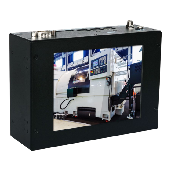
- Page 1 KS057R-FS 5.7” Fanless Touch Panel PC User’s Manual A54000929 Chapter 1 Introduction www.dfi.com...
-
Page 2: Copyright
Product names or trademarks appearing in this manual are for identification purpose only and Shielded interface cables must be used in order to comply with the emission limits. are the properties of the respective owners. Chapter 1 Introduction www.dfi.com... -
Page 3: Table Of Contents
About the Package ..............5 Chapter 1 - Introduction ............6 Overview .................6 Key Features ................6 Specifications ................7 Getting to Know the KS057R-FS ..........8 Mechanical Dimensions ............9 Chapter 2 - Getting Started ..........10 Chapter 3 - Installing Devices ..........11 Removing the Chassis Cover ........... 11 Installing a Mini PCIe Card ............. -
Page 4: About This Manual
An electronic file of this manual may be included in a support DVD. If not, you can download It is quite easy to inadvertently damage your PC, system board, components or devices even it and other product related documentation from our website at www.dfi.com. before installing them in your system unit. Static electrical discharge can damage computer components without causing any signs of physical damage. -
Page 5: Safety Precautions
• Disconnect the system from the DC outlet before cleaning. Use a damp cloth. Do not use liquid or spray detergents for cleaning. Chapter 1 Introduction www.dfi.com... -
Page 6: Chapter 1 - Introduction
Chapter 1 Chapter 1 - Introduction Key Features Overview Model Name KS057R-FS KS057R-FS Processor NXP i.MX6 Cortex-A9 DualLite, 1.0 GHz Two LAN ports on the connector panel Two COM ports (via DB-9 & terminal block) on the connector panel Status LED... -
Page 7: Specifications
Operating Temperature: -20 to 60°C (with extended temperature Note: peripherals, ambient with air flow) *Optional items are not supported in standard model. Please contact your sales repre- Storage Temperature: -30 to 80°C sentative for more information. Relative Humidity: 5 to 90% RH (non-condensing) Chapter 1 Introduction www.dfi.com... -
Page 8: Getting To Know The Ks057R-Fs
Chapter 1 Getting to Know the KS057R-FS Connector Panel View Side View Antenna hole Status LED Reset (green) Antenna hole Grounding USB 2.0 COM (RS485) COM (RS232) DC-in HDMI LAN 2 LAN 1 (GbE) (GbE) DC-in Wireless Antenna Holes Plug a power adapter into this socket. The acceptable power voltage/type is 12V/DC. -
Page 9: Mechanical Dimensions
Chapter 1 Mechanical Dimensions Top View Right View 57.50 170.20 Front View Bottom View Chapter 1 Introduction www.dfi.com... -
Page 10: Chapter 2 - Getting Started
The following devices can be installed in the system. • Mini PCIe card Installing an Operating System The device platform is an embedded system with Yocto 1.8 beta or Android 5.1 beta pre- loaded on the eMMC. Chapter 2 Getting Started www.dfi.com... -
Page 11: Chapter 3 - Installing Devices
Antenna hole Mounting screw Note: If installing a wireless module, place the antenna cable(s) on top of the Mini PCIe and route the cables to the side of the chassis to reach the antenna holes. Chapter 3 Installing Devices www.dfi.com... -
Page 12: Chapter 4 - Jumper Settings
SW5 switch is located on the back side of the system board. It is for development and troubleshooting which should only be performed by developers and service technicians who are fully aware of the outcome of any changes to the settings. www.dfi.com Chapter 4 Jumper Settings... -
Page 13: Chapter 5 - Ports And Connectors
Chapter 5 Chapter 5 - Ports and Connectors Graphics Interface Panel I/O Ports The system has one display port: • HDMI port Status LED Reset (green) Grounding USB 2.0 COM (RS485) COM (RS232) DC-in LAN 2 LAN 1 HDMI (GbE) (GbE) The front panel I/O consists of the following ports: •... -
Page 14: Rj45 Lan Ports
Chapter 5 RJ45 LAN Ports 9~36V DC-in LAN 2 LAN 1 Features • 2 LAN ports built on Atheros AR8033-AL1B (10/100/1000Mbps) and Microchip LAN7500- This 2-pin terminal block is considered a low power solution. This connector is wired as an ABZJ (10/100/1000Mbps) external DC-in connector and reset button for power control. -
Page 15: Usb Ports
Chapter 5 USB Ports Serial Port COM 3: RS232 Front COM 3 Panel eMMC LVDS LCD Panel i.MX6 Cortex-A9 1 2 3 4 5 6 7 8 DDR3L DDR3L USB 2.0 The USB 2.0 ports (USB 1, 2 and 3) and OTG connector are used for USB communication. In addition, the USB OTG allows the board and the devices connected to it to switch back and The COM 1 port provides 2-wire RS485 communication with support for auto flow control. -
Page 16: I/O Connectors
Chapter 5 I/O Connectors Debug Connectors Expansion Slots Front JTAG JTAG COM 3 DC-in Panel JTAG DC-in USB 2.0 Panel Backlight/SATA Power USB 1-2 USB 2.0 Panel Backlight/SATA Power USB 1-2 LAN 2 eMMC Debug LED LAN 2 USB 2.0 Debug LED USB 3 LAN 1... -
Page 17: Front Panel Connector
Chapter 5 Front Panel Connector Battery Front Panel JTAG Front DC-in COM 3 Panel USB 2.0 Panel Backlight/SATA Power USB 1-2 LAN 2 eMMC Debug LED USB 2.0 USB 3 LAN 1 USB OTG LVDS LCD Panel COM 1 i.MX6 Cortex-A9 1 2 3 4 5 6 7 8 HDMI... -
Page 18: Chapter 6 - Mounting Options
2. Flush with the front panel Din-rail mount bracket Mounting screws Fix the device on the wall. The following picture shows the dimensions and location of wall mount screw holes. Install the device onto the rail. 186.00 170.20 Unit: mm Chapter 6 Mounting Options www.dfi.com... -
Page 19: Chapter 7 - Software Features
Support Android ADB shell Source code package (support by request) Android Support Android APK install AP/API Support I C, Watchdog and GPIO Provide support console for i.MX6 platform. (*) This feature depends on NXP’s support. Chapter 7 Supported Software www.dfi.com... -
Page 20: Din-Rail Mount
Chapter 7 Android Support Component Support Status Component Support Status Support Loopback test, BR 115200 (need DFI Linux user space utility) UART1 - RS485 Support Loopback test, BR 115200 (need DFI Linux user space utility) 5.1.1 UART2 - RS422 Android Version 3.14.52... - Page 21 1. Support "busybox lspci" console command for check PCIe card status. Support Android ADB Mini PCIe 2. For standard product, we only port ENLi AP12356 WiFi/BT module. Support Loopback test, BR 115200 by DFI Android UART demo APP Android Factory Support UART1 - RS485 Reset...
Need help?
Do you have a question about the KS057R-FS and is the answer not in the manual?
Questions and answers