Table of Contents
Advertisement
Quick Links
Download this manual
See also:
User Manual
KS070-BT Installation Guide
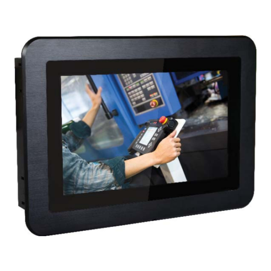
• One 7" Touch Panel PC
• One sheet of Poron foam
• One HDD drive bay kit
• 1 DVD disk includes:
- Manual
DFI reserves the right to change the specifi cations at any time prior to
the product's release. For the latest revision and more details of the
installation procedure, please refer to the user's manual on the website.
Package Contents
www.dfi .com
1
Advertisement
Table of Contents

Related Manuals for DFI KS070-BT


Summary of Contents for DFI KS070-BT
- Page 1 • 1 DVD disk includes: - Manual DFI reserves the right to change the specifi cations at any time prior to the product's release. For the latest revision and more details of the installation procedure, please refer to the user's manual on the website.
- Page 2 Panel COM 1 Power button (RS232/RS422/RS485) (Green LED) COM 2 HDMI (RS232/RS422/RS485) Status LED (Blue) COM 4/ 8-bit DIO Top View Reset Antenna USB 3.0 Antenna Antenna hole hole hole COM 3 (RS232/RS422/RS485) Mic-in LAN 1 LAN 2 Line-out Bottom View DC-in USB 2.0...
-
Page 3: Removing The Chassis Cover
Removing the Chassis Cover 1. Make sure the system and all other peripheral devices connected to it have been powered-off. 2. Disconnect all power cords and cables. 3. The 8 mounting screws on the rear side of the system are used to secure the cover to the chassis. -
Page 4: Installing A Sata Drive
Installing a SATA Drive 1. The SATA data and power connectors are on the system board. SATA connectors SATA mounting location 2. Align the mounting holes of the SATA HDD with the mounting holes on the HDD drive bay and use the provided mounting screws to attach the SATA HDD to the drive bay. - Page 5 3. Connect one end of the SATA cable to the SATA power and data connectors on the SATA drive and the other end of the SATA cable to the SATA power and data connectors on the system board. SATA connectors 4.
-
Page 6: Installing A Mini Pcie Card
Installing a Mini PCIe Card The system board is equipped with 3 Mini PCIe slots: two full-size and one half-size slots. Here we will demonstrate the installation of a full-size Mini PCIe card (mSATA interface) for capacity expansion. 1. Grasp the Mini PCIe card by its edges and align the notch in the connector of the PCIe card with the notch in the connector on the system board. -
Page 7: Mounting Options
Mounting Options Wall mount The wall mount kit includes the following: • 2 wall mount brackets • Bracket screws Wall mount bracket 1 Wall mount bracket 2 1. Before starting any installation procedures, attach the poron foam to the Panel PC. Poron foam 2. - Page 8 4. Attach the other bracket (wall mount bracket 2) to the rear of the Panel PC. Mounting screw Wall mount bracket 2 Hooks 5. Slide the Panel PC to "wall mount bracket 1" to attach the two brackets with the hooks. Then tighten the screw to secure the assembly in place. Screw...
-
Page 9: Panel Mount
Panel mount The panel mounting kit includes the following: • 6 mounting clamps 1. Before starting any installation procedures, attach the poron foam to the Panel PC. Poron foam 2. Select a place on the panel (or wall) where you will mount the Panel PC. 3. - Page 10 White plastic cap Mounting clamp Slit for mounting the clamp 6. The fi rst and second clamps must be positioned and secured diagonally fi prior to mounting the rest of the clamps. Tighten the clamp’s screw using an electric screwdriver by pressing the white plastic cap onto the back of the panel.
-
Page 11: Board Layout And Jumper Settings
Board Layout and Jumper Settings USB Power Select: 0 (JP5), 1-2 (JP6), 5-7 (JP7) Auto Power-on Select JP25 +5V_standby (default) 1-2 On Power-on via power button (default) 1-2 On 2-3 On Power-on via AC power 2-3 On JP18 (DIO 4-7) Clear CMOS Data JP24 Digital I/O Output State...
Need help?
Do you have a question about the KS070-BT and is the answer not in the manual?
Questions and answers