
Related Manuals for DFI KS104-CD


Summary of Contents for DFI KS104-CD
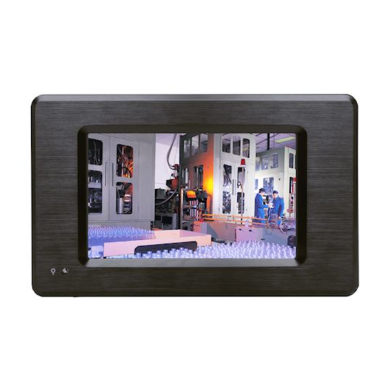
- Page 1 KS104-CD 10.4” Touch Panel PC User’s Manual A34600448 Chapter 1 Introduction www.dfi .com...
-
Page 2: Copyright
Copyright FCC and DOC Statement on Class B This publication contains information that is protected by copyright. No part of it may be re- This equipment has been tested and found to comply with the limits for a Class B digital produced in any form or by any means or used to make any transformation/adaptation without device, pursuant to Part 15 of the FCC rules. -
Page 3: Table Of Contents
......................6 Battery ....................... 30 Key Features ....................6 Specifications Chapter 5 - Mounting Options ....................7 ..............31 Getting to Know the KS104-CD ............... 8 Wall Mount ....................31 Mechanical Dimensions ................8 Panel Mount ....................32 Chapter 2 - Getting Started .............. -
Page 4: About This Manual
About this Manual Static Electricity Precautions An electronic file of this manual is included in the CD. To view the user’s manual in the CD, in- It is quite easy to inadvertently damage your PC, system board, components or devices even sert the CD into a CD-ROM drive. -
Page 5: Safety Precautions
Safety Precautions About the Package • Use the correct DC input voltage range. The package contains the following items. If any of these items are missing or damaged, please contact your dealer or sales representative for assistance. • Unplug the power cord before removing the system chassis cover for installation or servic- ing. -
Page 6: Chapter 1 - Introduction
Chapter 1 Chapter 1 - Introduction Key Features Overview Model Name KS104-CD KS104-CD Processor Intel ® Atom N2800 ® Chipset Intel NM10 Express Chipset 2 LAN ports 3 COM ports Display 1 VGA 2 USB 2.0 ports Audio Realtek ALC886 2-channel High Defi nition Audio... -
Page 7: Specifications
Chapter 1 Specifications ® Processor • Intel Atom N2800, 1.86GHz, 2x 512K L2, 6.5W TDP, dual-core Expansions • 1 Mini PCIe slot - Supports PCIe (PCIe and USB signals) or mSATA module ® Chipset • Intel NM10 Express chipset - Supports half size card Memory •... -
Page 8: Getting To Know The Ks104-Cd
Chapter 1 Getting to Know the KS104-CD Mechanical Dimensions KS104-CD Bottom View LAN 1 COM 3 Power LED LAN 2 Line-out Power Switch Top View 270.00 COM 1 Mic-in COM 2 USB 2.0 DC-in COM Ports Used to connect a serial device. - Page 9 Chapter 1 Motherboard Dimension 3.20 3.20 0.00 0.00 34.12 53.74 59.86 76.12 87.47 95.20 95.20 98.80 98.80 Chapter 1 Introduction www.dfi .com...
-
Page 10: Chapter 2 - Getting Started
Chapter 2 Chapter 2 - Getting Started Preparing the System Before you start using the system, you need the following items: • SATA hard drive • AC power adapter • PS/2 or USB keyboard • PS/2 or USB mouse • CD-ROM drive (for installing software/drivers) •... -
Page 11: Chapter 3 - Installing Devices
Chapter 3 Chapter 3 - Installing Devices 5. The SODIMM socket and the SATA drive bay are readily accessible after removing the chas- sis cover. Removing the Chassis Cover 1. Make sure that the system and all other peripheral devices connected to it have been powered-off. -
Page 12: Installing The Sodimm
Chapter 3 Chapter 2 Installing the SODIMM 3. Grasping the module by its edges, align the module into the socket at an approximately 30 degrees angle. Apply firm even pressure to each end of the module until it slips down into the socket. -
Page 13: Installing The Sata Drive
Chapter 3 Installing the SATA Drive 3. Align the mounting holes of the SATA drive with the mounting holes on the HDD bracket and then use the provided mounting screws to secure the drive in place. 1. Locate the SATA drive bay on the system. SATA drive HDD bracket SATA drive bay... - Page 14 Chapter 3 5. Place the SATA drive (with HDD bracket) into the system unit. Tighten the 4 mounting screws you removed in step 2. Mounting screw Chapter 3 Installing Devices www.dfi .com...
-
Page 15: Chapter 4 - Hardware Installation
Chapter 4 Chapter 4 - Hardware Installation Board Layout Front Panel System Fan SATA Power Battery DIO Power Chassis Intrusion Clear COM3 Front Audio CMOS (JP7) COM2 USB 2-5 Power Standby Power Fintek Seletct (JP6) F81866 COM6 COM5 SPI Flash BIOS USB 2.0 Mini PCIe/mSATA Select (JP8) USB 2-3... -
Page 16: System Memory
Chapter 4 Jumper Settings Important: Electrostatic discharge (ESD) can damage your board, processor, disk drives, add-in Clear CMOS Data boards, and other components. Perform installation procedures at an ESD workstation only. If such a station is not available, you can provide some ESD protection by wear- ing an antistatic wrist strap and attaching it to a metal part of the system chassis. -
Page 17: Usb Power Select
Chapter 4 USB Power Select Panel Power Select 2 4 6 USB 2-5 (JP6) 1 3 5 1-2 On: +5V 2-3 On: 1-2 On: +12V +5V_standby (default) 2 4 6 USB 0-1 (JP4) 1 3 5 1-2 On: +5V 2-3 On: +5V_standby 3-4 On: +5V (default) -
Page 18: Lvds Panel Select
Chapter 4 LVDS Panel Select Note: The default setting is eDP. 1. 1366x768: N2000 series processor supports eDP only. 2. 1600x1200: N2000 series processor supports DP only. 3. 1920x1080: D2000 series processor supports eDP only. 4. 1920x1200: D2000 series processor supports DP only. SW2 is used to select the resolution of LVDS panel on the system. -
Page 19: Power-On Select
Chapter 4 Power-on Select COM 2 RS232/RS422/RS485 Select COM 2 1-2 On: Power-on via power button (default) JP3 is used to configure the COM port 2 to RS232, RS422 (Full Duplex) or RS485. The pin function of the COM port will vary according to the jumper’s setting. 2-3 On: Auto power-on JP5 is used to select the method of powering on the system. -
Page 20: Mini Pcie/Msata Select
Chapter 4 Mini PCIe/mSATA Select 1-4-7-10, 2-5-8-11 On: Mini PCIe (default) 2-5-8-11, 3-6-9-12 On: mSATA JP8 is used to select the Mini PCIe signal. Chapter 4 Hardware Installation www.dfi .com... -
Page 21: Ports And Connectors
Chapter 4 Ports and Connectors COM (Serial) Ports Bottom Panel I/O Ports COM 3 COM 2 COM 2 : RS232/422/485 COM 6 LAN 1 COM 3 Power LED LAN 2 Line-out COM 4 Power Switch COM 5 COM 1: RS232 COM 3 to COM 6: RS232 COM 1... -
Page 22: Graphics Interface
Chapter 4 Graphics Interface RJ45 LAN Ports The display port consists of the following: • VGA port LAN 1 LAN 2 LAN 1 LAN 2 Features VGA Port The VGA port is used for connecting a VGA monitor. Connect the monitor’s 15-pin D-shell cable •... -
Page 23: Usb Ports
Chapter 4 USB Ports Wake-On-USB Keyboard/Mouse The Wake-On-USB Keyboard/Mouse function allows you to use a USB keyboard or USB mouse to wake up a system from the S3 (STR - Suspend To RAM) state. To use this function: • Jumper Setting JP4 and JP6 must be set to “2-3 On: +5V_standby”. -
Page 24: Dc-In
Chapter 4 DC-in I/O Connectors Digital I/O Connector Digital I/O Power Connector Digital I/O Digital I/O power DC-in This jack provides maximum of 60W power and is considered a low power solution. Connect a DC power cord to this jack. Use a power adapter with 12V DC output voltage. Using a volt- age higher than the recommended one may fail to boot the system or cause damage to the The 8-bit Digital I/O connector provides powering-on function to external devices that are con- system board. -
Page 25: Lvds Lcd Panel Connector
Chapter 4 LVDS LCD Panel Connector LVDS LCD Panel Connector LCD/Inverter Power Connector LCD/Inverter Power Connector Pins Function Pins Function Pins Function LVDS_Out3+ LVDS_Out7+ LVDS_Out3- LVDS_Out7- Panel Inverter Brightness Voltage Control Panel Power LVDS_Out2+ LVDS_Out6+ +3.3V LVDS_Out2- LVDS_Out6- Panel Backlight On/Off Control LVDS LCD +12V Panel... -
Page 26: Cooling Fan Connectors
Chapter 4 Cooling Fan Connectors Front Panel Connector System Fan Ground Power Sense Ground CPU Fan Power Sense HDD-LED - HDD LED This LED will light when the hard drive is being accessed. The fan connectors are used to connect cooling fans. The cooling fans will provide adequate RESET SW - Reset Switch airflow throughout the chassis to prevent overheating the CPU and system board components. -
Page 27: Sata (Serial Ata) Connector
Chapter 4 SATA (Serial ATA) Connector Front Audio Connector Line OUT-L Line OUT-JD SATA Power Mic-JD Line OUT-R Mic IN-R Mic IN-L SATA 0 SATA 2.0 3Gb/s Features The front audio connector allows you to connect to the second line-out and mic-in jacks that •... -
Page 28: Chassis Intrusion Connector
Chapter 4 Chassis Intrusion Connector Standby Power LED Ground Signal Standby Power LED The board supports the chassis intrusion detection function. Connect the chassis intrusion This LED will lit red when the system is in the standby mode. It indicates that there is power sensor cable from the chassis to this connector. -
Page 29: Compactflash Socket
Chapter 4 CompactFlash Socket Expansion Slot CompactFlash Socket Mini PCI Express Mini PCIe Slot The CompactFlashTM socket is used for inserting a CompactFlashTM card. CompactFlashTM card is a small removable mass storage device designed with flash technology - a non-volatile The Mini PCIe socket is used to install a Mini PCIe card. -
Page 30: Battery
Chapter 4 Battery Ground Battery Connect to the battery connector battery The lithium ion battery powers the real-time clock and CMOS memory. It is an auxiliary source of power when the main power is shut off. Safety Measures • Danger of explosion if battery incorrectly replaced. •... -
Page 31: Chapter 5 - Mounting Options
Chapter 5 Chapter 5 - Mounting Options 3. Attach the other bracket (wall mount bracket 2) to the rear of the Panel PC. Wall Mount The wall mount kit includes the following: • 2 Wall mount brackets • Bracket screws Mounting screw Wall mount bracket 2 Hooks... -
Page 32: Panel Mount
Chapter 5 Panel Mount 5. Tighten the screw to hold the assembly in place. The panel mounting kit includes the following: • 6 mounting clamps Mounting screw Select a place on the panel where you will mount the Panel PC. Cut out a shape on the panel that corresponds to the Panel PC’s rear dimensions (251mm x 201mm). - Page 33 Chapter 5 4. Slide the Panel PC through the hole until it is properly fi tted against the panel. 5. Position the mounting clamps along the rear edges of the Panel PC, fi tting them into the slits that are around the Panel PC. Mounting clamp Slit for mounting...
-
Page 34: Chapter 6 - Bios Setup
Chapter 6 Chapter 6 - BIOS Setup Legends Overview Keys Function The BIOS is a program that takes care of the basic level of communication between the CPU and peripherals. It contains codes for various advanced features found in this system board. Right and Left arrows Moves the highlight left or right to select a menu. -
Page 35: Ami Bios Setup Utility
Aptio Setup Utility - Copyright (C) 2012 American Megatrends, Inc. Project Version 1APJK 0.15.013 x64 Main Advanced Chipset Boot Security Save & Exit Model Name DFI CD951-C Bios Name CD9510C9.21A Legacy OpROM Support F81866A WDT Parameters. Bios Version RA15 Launch I82574 PXE [Disabled] Build Date and Time... - Page 36 Chapter 6 PCI Subsystem Settings ACPI Power Management Configuration This section is used to configure the PCI Subsystem. This section is used to configure the ACPI Setting. Aptio Setup Utility - Copyright (C) 2012 American Megatrends, Inc. Aptio Setup Utility - Copyright (C) 2012 American Megatrends, Inc. Advanced Advanced ACPI Power Management Confi...
- Page 37 Chapter 6 IDE Configuration CPU Configuration This section is used to configure IDE functions. This section is used to configure the CPU. It will also display the detected CPU information. Aptio Setup Utility - Copyright (C) 2012 American Megatrends, Inc. Aptio Setup Utility - Copyright (C) 2012 American Megatrends, Inc.
- Page 38 Chapter 6 USB Configuration Super IO Configuration This section is used to configure USB. This section is used to configure the I/O functions supported by the onboard Super I/O chip. Aptio Setup Utility - Copyright (C) 2012 American Megatrends, Inc. Aptio Setup Utility - Copyright (C) 2012 American Megatrends, Inc.
- Page 39 Chapter 6 Serial Port 1 Configuration to Serial Port 6 Configuration Aptio Setup Utility - Copyright (C) 2012 American Megatrends, Inc. Aptio Setup Utility - Copyright (C) 2012 American Megatrends, Inc. Advanced Advanced Serial Port 1 Confi guration Serial Port 3 Confi guration Enable or Disable Serial Select an Optimal Setting Port (COM)
- Page 40 Chapter 6 PC Health Status This section displays the hardware health monitor. Aptio Setup Utility - Copyright (C) 2012 American Megatrends, Inc. Advanced Aptio Setup Utility - Copyright (C) 2012 American Megatrends, Inc. Serial Port 5 Confi guration Select an Optimal Setting Advanced for Super IO device Serial Port...
- Page 41 Chapter 6 JMB36X ATA Controller Configuration WatchDog Config This section is used to configure the serial port functions. This section is used to configure the watchdog functions. Aptio Setup Utility - Copyright (C) 2012 American Megatrends, Inc. Aptio Setup Utility - Copyright (C) 2012 American Megatrends, Inc. Advanced Advanced Not Present...
- Page 42 Chapter 6 Chipset Host Bridge This section configures relevant chipset functions. Aptio Setup Utility - Copyright (C) 2012 American Megatrends, Inc. Chipset Aptio Setup Utility - Copyright (C) 2012 American Megatrends, Inc. Confi g Memory Frequen- Memory Frequency and Timing cy and Time Settings.
- Page 43 Chapter 6 Memory Frequency and Timing Intel IGD Configuration This section is used to configure the TOLUD functions. This section is used to select the amount of system memory used by the internal graphics device. Aptio Setup Utility - Copyright (C) 2012 American Megatrends, Inc. Advanced Aptio Setup Utility - Copyright (C) 2012 American Megatrends, Inc.
- Page 44 Chapter 6 TPT Devices South Bridge Enable or disable Intel IO Controller Hub (TPT) devices Aptio Setup Utility - Copyright (C) 2012 American Megatrends, Inc. Aptio Setup Utility - Copyright (C) 2012 American Megatrends, Inc. Advanced Chipset Azalia Controller [HD Audio] Azalia Controller Enable/ Disable Intel (R) ...
- Page 45 Chapter 6 Boot Security Aptio Setup Utility - Copyright (C) 2012 American Megatrends, Inc. Aptio Setup Utility - Copyright (C) 2012 American Megatrends, Inc. Main Advanced Chipset Boot Security Save & Exit Main Advanced Chipset Boot Security Save & Exit Boot Confi...
-
Page 46: Updating The Bios
Chapter 6 Save & Exit Updating the BIOS To update the BIOS, you will need the new BIOS file and a flash utility, AFUDOS. EXE. Please contact technical support or your sales representative for the files. Aptio Setup Utility - Copyright (C) 2012 American Megatrends, Inc. Main Advanced Chipset... -
Page 47: Chapter 7 - Supported Software
Chapter 7 Chapter 7 - Supported Software Intel Chipset Software Installation Utility The CD that came with the system board contains drivers, utilities and software applications The Intel Chipset Software Installation Utility is used for updating Windows INF files so that ®... - Page 48 Chapter 7 Intel Graphics Drivers 3. Go through the readme document for system re- quirements and installation To install the driver, click “Intel Graphics Drivers” on the main menu. tips then click Next. 1. Setup is now ready to install the graphics driver.
- Page 49 Chapter 7 Audio Drivers 3. Go through the readme docu- ment for system requirements and installation tips then click To install the driver, click “Audio Drivers” on the main menu. Next. 1. Setup is now ready to install the driver. Click Next. 2.
- Page 50 Chapter 7 Intel LAN Drivers 4. Click Install to begin the installation. To install the driver, click “Intel LAN Drivers” on the main menu. 1. Setup is ready to install the driver. Click Next. 5. After completing installa- tion, click Finish. 2.
- Page 51 Chapter 7 Intel Rapid Storage Technology 3. Read the license agreement then click Yes. The Intel Rapid Storage Technology is a utility that allows you to monitor the current status of the SATA drives. It enables enhanced performance and power management for the storage subsystem.
- Page 52 Chapter 7 F6 Floppy Configuration Utility 6. Click “Yes, I want to restart my computer now” then click Finish. This is used to create a floppy driver diskette needed when you install Windows ® Restarting the system will allow the XP using the F6 installation method.
- Page 53 Chapter 7 DFI Utility 3. Enter “User name” and “Organization” information DFI Utility provides information about the board, Watchdog, DIO, and Backlight. then click “Next”. To access the utility, click “DFI Utility” on the main menu. Note: If you are using Windows 7, you need to access the operating system as an administrator to be able to install the utility.
- Page 54 Chapter 7 The DFI Utility icon will appear on the desktop. Double-click the icon to open the utility. Information WatchDog HW Health Chapter 7 Supported Software www.dfi .com...
- Page 55 Chapter 7 Adobe Acrobat Reader 9.3 To install the reader, click “Adobe Acrobat Reader 9.3” on the main menu. 1. Click Next to install or click Change Destination Folder to select another folder. Backlight 2. Click Install to begin installa- tion.
-
Page 56: Appendix A - Smart Fan Setting Guide
Appendix A Appendix A - NLITE and AHCI Installation Guide 4. Insert the XP installation disc into an optical drive. nLite 5. Launch nLite. The Welcome screen will appear. Click nLite is an application program that allows you to customize your XP installation disc by Next. - Page 57 Appendix A 7. Click Next. 9. Click Insert and then select Multiple driver folder to select the drivers you will integrate. Click Next. Select only the drivers ap- 8. In the Task Selection dialog propriate for the Windows box, click Drivers and version that you are using Bootable ISO.
- Page 58 Appendix A If you are uncertain of The program is currently the southbridge chip used integrating the drivers on your motherboard, and applying changes to select all RAID/AHCI the installation. controllers and then click When the program is finished applying the changes, click Next.
- Page 59 Appendix A To create an image, You have finished cus- select the Create Image tomizing the Windows mode under the General XP installation disc. Click section and then click Finish. Next. Enter the BIOS utility to configure the SATA con- troller to RAID/AHCI.
- Page 60 Appendix A AHCI 5. In the Hardware Update Wizard dialog box, select “No, not this time” then The installation steps below will guide you in configuring your SATA drive to AHCI mode. click Next. 1. Enter the BIOS utility and configure the SATA controller to IDE mode. 2.
- Page 61 Appendix A 8. Click “Have Disk”. A warning message appeared because the se- lected SATA controller did not match your hardware device. Ignore the warning and click Yes to proceed. Click Finish. 9. Select C:\AHCI\iaAHCI.inf and then click Open. The system’s settings have been changed.
-
Page 62: Appendix B - Watchdog Sample Code
Appendix B Appendix B - Watchdog Sample Code ;Software programming example: ;--------------------------------------------- ;(1) Enter Super IO Confi guration mode ;--------------------------------------------- DX,2EH AL,87H DX,AL DX,AL ;------------------------------------------------------------------------------------------- ;(2) Confi guration Logical Device 7, register CRF5/CRF6 (WDT Control /WDT timer) ;------------------------------------------------------------------------------------------- DX,2EH AL,07H ;Ready to Program Logical Device DX,AL DX,2FH... -
Page 63: Appendix C - System Error Message
Appendix C Appendix C - System Error Message Hard Disk(s) fail (20) When the BIOS encounters an error that requires the user to correct something, either a beep HDD initialization error. code will sound or a message will be displayed in a box in the middle of the screen and the message, PRESS F1 TO CONTINUE, CTRL-ALT-ESC or DEL TO ENTER SETUP, will be shown in Hard Disk(s) fail (10) the information box at the bottom. -
Page 64: Appendix D - Troubleshooting Checklist
Appendix D Appendix D - Troubleshooting Checklist The picture seems to be constantly moving. Troubleshooting Checklist 1. The monitor has lost its vertical sync. Adjust the monitor’s vertical sync. This chapter of the manual is designed to help you with problems that you may encounter 2. -
Page 65: Hard Drive
Appendix D Hard Drive System Board 1. Make sure the add-in card is seated securely in the expansion slot. If the add-in card is Hard disk failure. loose, power off the system, re-install the card and power up the system. 1.
Need help?
Do you have a question about the KS104-CD and is the answer not in the manual?
Questions and answers