Table of Contents
Advertisement
Quick Links
Download this manual
See also:
Owner's Manual
Advertisement
Table of Contents
Troubleshooting

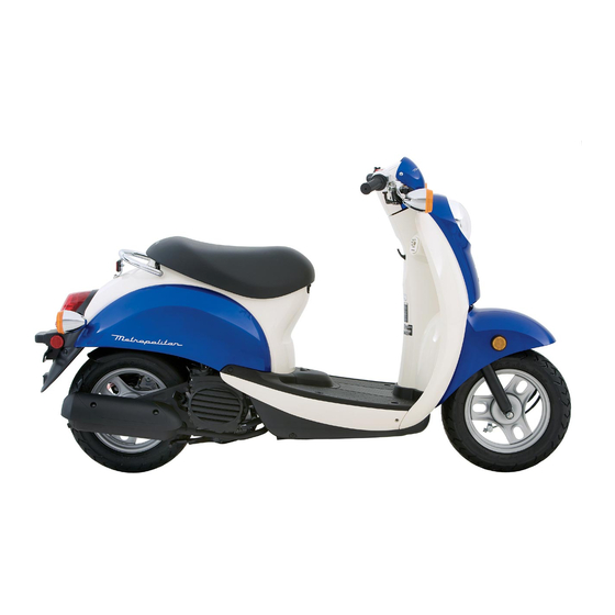
Summary of Contents for Honda Metropolitan CHF50
-
Page 3: Troubleshooting
OUT INCURRING ANY OBLIGATION WHATSO- EVER. NO PART OF THIS PUBLICATION MAY BE REPRODUCED WITHOUT WRITTEN PER- MISSION. THIS MANUAL IS WRITTEN FOR PERSONS WHO HAVE ACQUIRED BASIC KNOWLEDGE OF MAINTENANCE ON HONDA MOTORCYCLES, MOTOR SCOOTERS ATVS. Honda Motor Co., Ltd. - Page 8 GENERAL INFORMATION The safety certification label is attached on the leg shield. SAFETY CERTIFICATION LABEL The Emission Control Information Label (After ’05 model) is attached EMISSION CONTROL INFORMATION LABEL on the left side of the luggage box inside. The Emission Control Information Label (Canada type only: After ’05 model) is attached on the right side of the luggage box inside.
- Page 10 – At disassembly 0.7 liter (0.7 US qt, 0.6 lmp qt) – Recommended engine oil Pro Honda GN4 4-stroke oil (U.S.A. and – Canada) or an equivalent motor oil API service classification: SG or higher JASO T 903 standard: MA...
- Page 17 Throttle cable outer inside Cable lubricant Brake cable outer inside Seat lock cable outer inside Main stand lock cable outer inside Handlebar grip rubber inside Honda bond A or equivalent Air cleaner connecting tube-to-housing mating area Equalizer cover bolt threads Locking agent 1-13...
- Page 32 GENERAL INFORMATION MAIN WIRE HARNESS REAR BRAKE CABLE SEAT LOCK CABLE FUEL LEVEL SENSOR 3P (Bu) CONNECTOR THROTTLE CABLE AFTER ’07 MODEL: 1.0 – 3.0 mm IGNITION COIL (0.04 – 0.12 in) MAIN WIRE HARNESS SPARK PLUG WIRE FUEL HOSE SEAT LOCK CABLE THROTTLE CABLE REAR BRAKE CABLE...
- Page 33 GENERAL INFORMATION FUEL PUMP/IGNITION MAIN WIRE HARNESS COIL WIRE LOWER COVER ALTERNATOR/STARTER WIRE 1.0 – 3.0 mm AFTER ’07 MODEL: MAIN STAND LOCK (0.04 – 0.12 in) CABLE FUEL HOSE FUEL HOSE WIRE BAND WHITE TAPE IGNITION COIL WIRE SEAT LOCK CABLE 20°...
- Page 36 GENERAL INFORMATION RADIATOR RESERVE TANK AFTER ’07 MODEL: AIR SUCTION HOSE FUEL HOSE BATTERY 1.0 – 3.0 mm (0.04 – 0.12 in) SIPHON HOSE CARBURETOR VACUUM PISTON HOSE THROTTLE CABLE ENGINE BREATHER HOSE MAIN STAND LOCK CABLE FRAME IGNITION COIL WATER HOSE AIR SUPPLY HOSE IGNITION COIL WIRE...
-
Page 42: Noise Emission Control System
GENERAL INFORMATION EXHAUST EMISSION CONTROL SYSTEM (After ’05 model) SECONDARY AIR SUPPLY SYSTEM The secondary air supply system introduces filtered air into the exhaust gases in the exhaust port. Fresh air is drawn into the exhaust port whenever there is a negative pressure pulse in the exhaust system. This charge of fresh air promotes burning of the unburned exhaust gases and changes a considerable amount of hydrocarbons and carbon monoxide into relatively harmless carbon dioxide and water vapor. -
Page 90: Fuel System
FUEL SYSTEM SERVICE INFORMATION GENERAL • Work in a well ventilated area. Smoking or allowing flames or sparks in the work area or where gasoline is stored can cause a fire or explosion. • For fuel pump inspection, refer to page 4-5. •... - Page 184 FINAL REDUCTION COMPONENT LOCATION 26 N·m (2.7 kgf·m, 20 lbf·ft) 2002 only 10-4...
- Page 188 FINAL REDUCTION Remove the dowel pins. DOWEL PINS Clean any sealant from the transmission case mat- ing surface. Remove the thrust washers and countershaft. COUNTERSHAFT FINAL GEAR SHAFT Remove the final gear shaft, counter gear and side washer. WASHER 2002 only WASHERS COUNTER GEAR DRIVESHAFT REMOVAL...
- Page 193 FINAL REDUCTION Install the countershaft into the transmission case. COUNTER SHAFT Install the thrust washers onto the countershaft and final gear shaft. THRUST WASHER 2002 only THRUST WASHER Apply sealant to the transmission case mating sur- face. Install the dowel pins. DOWEL PINS Apply molybdenum oil solution to the countershaft and final gear shaft sliding surface.
-
Page 269: Ignition System
IGNITION SYSTEM If the peak voltage measured at the ECM connector is abnormal, measure the peak voltage at the pulse generator connector. Disconnect the alternator/starter 6P (W) connector 6P (W) CONNECTOR and connect the peak voltage tester or adaptor probes to the connector terminals of the alternator/ starter side. -
Page 270: Ignition Timing
IGNITION SYSTEM IGNITION TIMING • The ignition timing is factory preset and need only be checked when an electrical system com- ponent is replaced. Warm up the engine to normal operating tempera- PLUG ture. MAINTENANCE LID Stop the engine and remove the radiator cover (page 6-5) and plug maintenance lid. - Page 271 IGNITION SYSTEM Disconnect the throttle position sensor 3P connec- YELLOW/RED YELLOW/BLUE tor. Check the 3P connector for loose contact or cor- roded terminals. Measure the resistance between the Yellow/red and Yellow/blue wire terminals of the sensor side con- nector. STANDARD: 4 – 6 kΩ (20°C/68°F) Measure the resistance between the Blue/green and Yellow/blue wire terminals of the sensor side con- BLUE/GREEN...


Need help?
Do you have a question about the Metropolitan CHF50 and is the answer not in the manual?
Questions and answers
I locked the ignition now I don't know how to unlock it. Also how do you open the seat up