Table of Contents
Advertisement
Quick Links
Advertisement
Table of Contents

Related Manuals for LifeGear 30805


Summary of Contents for LifeGear 30805
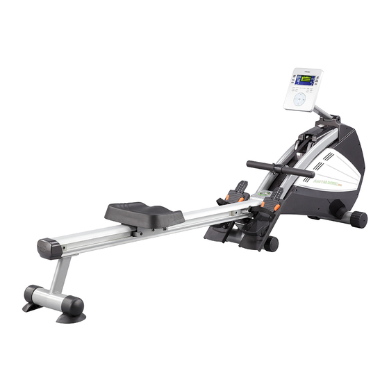
- Page 1 AIR MAGNETIC ROWER PC ITEM NO: 30805 OWNER’S MANUAL IMPORTANT: Read all instructions carefully before using this product. Retain this owner’s manual for future reference. The specifications of this product may vary from this photo, subject to change without notice.
-
Page 2: Table Of Contents
TABLE OF CONTENTS WARRANTY ------------------------------------------------------------------------------ 2 IMPORTANT SAFETY INSTRUCTIONS ------------------------------------------- 3 PARTS LIST ------------------------------------------------------------------------------- 4 HARDWARE LIST ------------------------------------------------------------------------ 5 TOOLS -------------------------------------------------------------------------------------- 5 OVERVIEW DRAWING ----------------------------------------------------------------- 6 ASSEMBLY INSTRUCTIONS --------------------------------------------------------- 7 SAFETY OPERATING INSTRUCTIONS ------------------------------------------- 13 MAINTENANCE -------------------------------------------------------------------------- 13 FOLDING UP THE ROWER ----------------------------------------------------------- 14 SETTING DOWN THE ROWER ------------------------------------------------------ 15 TRANSPORTATION --------------------------------------------------------------------- 16 OPERATING THE COMPUTER ------------------------------------------------------ 17... -
Page 3: Warranty
ONE YEAR LIMITED WARRANTY LifeGear Inc. warrants to the original purchaser that this product is free from defects in material and workmanship when used for the purpose intended, under the conditions that it has been installed and operated in accordance with LifeGear's Owner's Manual. LifeGear's obligation under this warranty is limited to replacing or repairing free of charge, any parts which may prove to be defective under normal home use. -
Page 4: Important Safety Instructions
IMPORTANT SAFETY INSTRUCTIONS Basic precautions should always be followed, including the following important safety instructions when using this equipment. Read all instructions before using this equipment. Read all instructions and follow it carefully before using this equipment. Make sure the equipment is properly assembled and tightened before use. -
Page 5: Parts List
PARTS LIST Description Qty No. Description 001 Main Frame 1 026 Bumper Stopper 28x28x37 Hexagon Socket Countersunk 002 Plastic Fan with Sensor Magnet 1 027 Head Cap Bolt M8x80mm 003 Pulling Strap Transmission Set 1 028 Aluminum Beam Cover 004 Strap Wheel Set 1 029 Rear Connect Plate 005 Handlebar 1 030 Rear Stabilizer... -
Page 6: Hardware List
PARTS LIST Description Qty No. Description 050 Power Supply Cable 1 062 Flat Washer M8xØ16x1.5T 051 Adapter 1 063 Self Tapping Screw 5/32"x1/2" 052 Sensor Wire 400mm 1 064 Self Tapping Screw 3/16"x5/8" 053 Computer Wire 400mm 1 065 Self Tapping Screw 3/16"x1/2" Hexagon Socket Head Bolt 4 066 Plastic Washer Ø32.45xØ38.5x2T M5x10mm... -
Page 7: Overview Drawing
OVERVIEW DRAWING... -
Page 8: Assembly Instructions
ASSEMBLY INSTRUCTIONS Tool: M6 Allen Wrench Step 1 Attach the Aluminum Beam (24) onto the Shaft Bracket (22) with six M8x16mm Hexagon Socket Head Bolts (41). Tighten bolts with the M6 Allen Wrench provided. Hardware: (41) Hexagon Socket Head Bolt M8x16mm 6 PCS... - Page 9 Tool: M6 Allen Wrench Step 2 Attach the Seat (40) onto the Seat Carriage (39) with four M8x16mm Hexagon Socket Head Bolts (41). Tighten bolts with the M6 Allen Wrench provided. Hardware: (41) Hexagon Socket Head Bolt M8x16mm 4 PCS...
- Page 10 Tool: M6 Allen Wrench Step 3 Attach the Rear Stabilizer (30) onto the Aluminum Beam (24) with four M8x16mm Hexagon Socket Head Bolts (41). Tighten bolts with the M6 Allen Wrench provided. Slide the Aluminum Beam Cover (28) onto the end of the Aluminum Beam (24). Hardware: (41) Hexagon Socket Head Bolt M8x16mm...
- Page 11 Tool: M6 Allen Wrench Step 4 Attach both Right/Left Lower Foot Pedals (17R, 17L) onto the Main Frame (1) with the Foot Pedal Connection Plate (56) and two M8x25mm Hexagon Socket Countersunk Head Cap Bolts (69). Tighten bolts with the M6 Allen Wrench provided. Hardware: (69) Hexagon Socket Countersunk Head Cap Bolt M8x25mm...
- Page 12 (31) (21) LOCK POSITION Step 5 1. To set down the Aluminum Beam (24), firmly hold the Aluminum Beam (24) with one hand and the other hand to pull the Lock Pin Ball (34) with Lock Pin (34B). 2. Carefully lower the Aluminum Beam (24) until the Rear Stabilizer End Caps (31) to the ground.
- Page 13 Step 6 Plug the wire of the Adapter (51) into the power jack of the Power Supply Cable (50) and then connect the Adapter (51) to the electrical wall outlet.
-
Page 14: Safety Operating Instructions
SAFETY OPERATING INSTRUCTIONS INCORRECT CORRECT UNLOCK POSITION LOCK POSITION The Lock Pin is NOT in the lock Make sure the Lock Pin is in the lock position. position before using the rower. WARNING: Please make sure the Lock Pin is in the lock position to prevent serious injury from occurring. -
Page 15: Folding Up The Rower
FOLDING UP THE ROWER (21) (34B) (24) LOCK POSITION (34B) 1. With one hand to hold the Pedal Strap (21). 2. Pull the Pedal Strap (21) up until the Lock Pin (34B) can be pulled out. 3. Lower the Main Frame (1) to the ground. 4. -
Page 16: Setting Down The Rower
SETTING DOWN THE ROWER (24) (24) (31) (34B) (21) LOCK POSITION To set down the Aluminum Beam (24), firmly hold the Aluminum Beam (24) with one hand and the other hand to pull the Lock Pin (34B). Carefully lower the Aluminum Beam (24) until the Rear Stabilizer End Caps (31) to the ground. -
Page 17: Transportation
TRANSPORTATION REAR STABILIZER TRANSPORTATION WHEEL Rower has TRANSPORTATION WHEELS located at the Front Stabilizer End Cap. This enables user to easily move the rower. From the folded position GRASP the REAR STABILIZER of the rower and tilt the machine until the TRANSPORTATION WHEELS are engaged with the floor. -
Page 18: Operating The Computer
OPERATING THE COMPUTER COMPUTER KEY FUNCTIONS: START/STOP: To start and stop the workout session. ENTER: To confirm your selection. RESET: Press the RESET key to reset the functional values to zero when you are presetting the functional values. Press the RESET key for over 2 seconds, all functional values will reset to zero and the computer screen will display STOP, MANUAL, PROGRAM, WATT, USER, H.R.C., and RACE exercise modes image. - Page 19 countdown is complete, the Pulse Recovery grade will be displayed. Your ratings for Pulse Recovery are as follows: F1 = Excellent F4 = Below Average F2 = Good F5 = Not Good F3 = Fair F6 = Poor COMPUTER DISPLAY FUNCTIONS: TM (TIME): Displays the workout time.
-
Page 20: Getting Started
GETTING STARTED: Plug the wire of the adapter into the power jack, which is located in the front of the machine and then connect the adapter to the electrical wall outlet. The computer screen will display U0 with a long BI tone, press the + or - key to select USER number (U0-U4) and press Enter key to confirm the User number. - Page 21 Press the ENTER key for confirmation. At this point you can press the START/STOP key to start your workout or you can set LEVEL or a goal as described above. TRAINING IN WATT MODE: When the computer screen displays STOP, MANUAL, PROGRAM, WATT, USER, H.R.C., and RACE modes, press the + or - key to select the WATT control program mode and then press the ENTER key for confirmation.
- Page 22 select a program, use the + or - key. If user selects 55% heart symbol and the target heart rate will be 107 displaying on the split window of PULSE because user has inputted USER data (gender, age, height, and weight) after the adapter connected to the electrical wall outlet.
- Page 23 level according to the heart rate detected. For example, the resistance level will increase while the heart rate detected is lower than Target Heart Rate. Also, the resistance level will decrease while the heart rate detected is higher than Target Heart Rate. As a result, the user’s heart rate will be adjusted to equal the Target Heart Rate.
-
Page 24: Adjustments
ADJUSTMENTS (38) Computer COMPUTER ANGLE AND HEIGHT ADJUSTMENT Tool: The Computer (38) angle and height can be adjusted in a wide range. After long use, the Computer Post (32) may get loose. Tighten the Computer Post (32) by screwing the M8 Allen Wrench Bolt (59) clockwise with the M8 (32) Computer Post... -
Page 25: How To Row
HOW TO ROW Take up the initial Push yourself Continue movement position leaning backwards, straight until you are leaning forward, knees bent your back and legs at slightly backwards, and arms straight. the same time. bending the arms at the same time. ALTERNATIVE EXERCISE Return to 1 and repeat. -
Page 26: Warm Up And Cool Down Routine
WARM UP AND COOL DOWN ROUTINE The WARM-UP is an important part of any workout. The purpose of warming up is to prepare your body for exercise and to minimize injuries. Warm up for two to five minutes before aerobic exercising. Warming up should prepare your body for more strenuous exercise by heating up and stretching your muscles, increasing your circulation and pulse rate, and delivering more oxygen to your muscles. - Page 27 QUADRICEPS STRETCH With one hand against a wall for balance, reach behind you and pull your right foot up. Bring your heel as close to your buttocks as possible. Hold for 15 counts and repeat with left foot. INNER THIGH STRETCH Sit with the soles of your feet together and your knees pointing outward.
Need help?
Do you have a question about the 30805 and is the answer not in the manual?
Questions and answers