Table of Contents
Advertisement
Advertisement
Table of Contents

Related Manuals for LifeGear 75164


Summary of Contents for LifeGear 75164
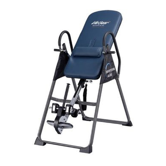
- Page 1 INVERSION TABLE with Memory Foam ITEM NO: 75164 OWNER’S MANUAL IMPORTANT: Read all instructions carefully before using this product. Retain this owner’s manual for future reference. The specifications of this product may vary from this photo and are subject to change without...
-
Page 2: Table Of Contents
TABLE OF CONTENTS WARRANTY ------------------------------------------------------------------------------ 2 IMPORTANT SAFETY INSTRUCTIONS ------------------------------------------- 3 EXPLODED VIEW ----------------------------------------------------------------------- 5 PARTS LIST ------------------------------------------------------------------------------- 6 HARDWARE AND TOOLS PACK ---------------------------------------------------- 8 ASSEMBLY INSTRUCTIONS --------------------------------------------------------- 9 SAFETY OPERATING INSTRUCTIONS ------------------------------------------- 15 HOW TO USE ----------------------------------------------------------------------------- 16 QUICK RELEASE ANKLE LOCK ----------------------------------------------------- 18 OPERATION ------------------------------------------------------------------------------- 19 WARM UP AND COOL DOWN ROUTINE ----------------------------------------- 21... -
Page 3: Warranty
ONE YEAR LIMITED WARRANTY LifeGear Inc. warrants to the original purchaser that this product is free from defects in material and workmanship when used for the purpose intended, under the conditions that it has been installed and operated in accordance with LifeGear's Owner's Manual. LifeGear's obligation under this warranty is limited to replacing or repairing free of charge, any parts which may prove to be defective under normal home use. -
Page 4: Important Safety Instructions
IMPORTANT SAFETY INSTRUCTIONS This inversion table was designed and built for optimum safety. However, certain precautions apply whenever you operate the exercise equipment. Be sure to read the entire manual before assembling and operating this equipment. When using an appliance, basic precautions should always be followed, including the following: WARNING - To reduce the risk of injury to persons:... - Page 5 WARNING - Risk of personal injury - Keep body parts, hair, loose clothing and jewelry clear of all moving parts. NOTE: Maximum user weight for this product is 350 lbs / 160 kgs. Maximum Rated Height for this product is 200 cm. WARNING: Before using this equipment you should consult with your personal physician to see if inversion equipment is appropriate for you.
-
Page 6: Exploded View
EXPLODED VIEW... -
Page 7: Parts List
PARTS LIST Description Description Front U-Frame Loop Strap Rear U-Frame Strap Lock Adjustable Boom Foam Bed Bed Frame Foam Grip Pivot Arm Protective Cover Adjustable Lock Plate Hex Head Bolt M8x23 Steel Heel Holder Bracket Front Plastic Cover Folding Arm 040L Left Plastic Cover Rear Rod 040R Right Plastic Cover... - Page 8 PARTS LIST Description Qty No. Description Bolt M6x30 1 070 Bolt M5x10 Spacer Ø22x16.8 2 071 Bolt M8x50 Screw ST4.2x12 8 072 Pivot Arm Ring Screw ST4.8x20 1 073 Phillips Screw M4x16 Shaft Nut Ø8...
-
Page 9: Hardware And Tools Pack
HARDWARE AND TOOLS PACK (43) Hex Head Bolt (15) Lock Nut 2 PCS 2 PCS (13) Washer 4 PCS (38) Hex Head Bolt (15) Lock Nut 2 PCS 2 PCS (13) Washer 4 PCS (48) Bolt (51) Bolt 4 PCS 4 PCS (55) Nut Cap (54) Washer... -
Page 10: Assembly Instructions
ASSEMBLY INSTRUCTIONS Step 1 Stand up the base of the machine by separating the Front and Rear U-Frames (1, 2). Pull the Front and Rear U-Frames (1, 2) as far apart from each other as possible. Then push down on the middle of the two Folding Arms (8) until they are fully locked down. Step 2 Lay the base on its side as shown. - Page 11 bolts with the Multi Hex Tool with Phillips Screwdriver provided. Hardware: (48) Bolt (51) Bolt (54) Washer 4 PCS 4 PCS 8 PCS ------------------------------------------------------------------------------------------- (55) Nut Cap 2 PCS Step 3 Install two Nut Caps (55) onto Lock Nuts (15). Slide one Protective Cover (37) on to each side of the base as shown, and pull down on the Protective Covers (37) until the bottom of the covers are slightly lower than the Folding Arms (8).
- Page 12 Step 4 Slide the bottom of the Pivot Arms (5) into the brackets, located at each side of the Bed Frame (4), align to the desired hole on the arm with the peg on the bracket. Insert the peg into the hole to lock the Pivot Arms (5) in place. It is recommended that you use the bottom hole on the Pivot Arms (5) until you become more familiar with the equipment.
- Page 13 NOTE: Make sure the lock teeth are wedged into the slots in the Rear and Front Rods (11, 9) to lock the Steel Heel Holder Brackets (7) and Rubber Heel Holders (31) in place as shown in figures A and B before use. Step 6 Slide two Steel Heel Holder Brackets (7) and two Rubber Heel Holders (31) onto both ends of the Rear Rod (9) until the lock teeth are wedged into the slots in the Rear Rod (9), as...
- Page 14 13 15 38 13 (55) Nut Cap 2 PCS Step 8 Attach the top end of Handlebar (29) onto the Rear U-Frame (2) and Pivot Arm Ring (72) with one Hex Head Bolt (38), one Lock Nut (15), and two Washers (13). Tighten Bolt and Lock Nut with the Multi Hex Tool with Phillips Screwdriver and Wrench provided.
- Page 15 Step 9 Attach the Nylon and Loop Straps (32, 33) to the inversion table by hooking the Safety Hook (19) on the end of the Nylon Strap (32) to the loop on the back of the Bed Frame (4) as shown.
-
Page 16: Safety Operating Instructions
SAFETY OPERATING INSTRUCTIONS Incorrect Correct Pivot arm is NOT aligned correctly. Make sure the pivot arm is inserted all The pivot arm is not inserted all the way into the slot. Pivot arm is the way into the curved slot. aligned correctly when the groove sits directly on the curved slot and the pivot arm is able to rotate freely. -
Page 17: How To Use
HOW TO USE SHORTEN LENGTHEN Adjusting the Strap For added safety, a nylon strap has been included to restrict the degree of inversion. This strap can be adjusted to different lengths to allow for a greater or lesser degree of inversion. To lengthen the Nylon Strap (32) feed the top end of Nylon Strap (32) into the strap lock, and pull on the lower end of the strap. - Page 18 Mounting the table Pull the Adjustable Handle until the heel holders lock on the feet securely. Wearing shoes will help ankles stay more secure. Dismounting the table 1. Pull the Adjustable Handle. 2. Press the Button. 3. Push the Adjustable Handle forward.
-
Page 19: Quick Release Ankle Lock
QUICK RELEASE ANKLE LOCK Before mounting the table, press the button on top and pull open. Pull the handle to lock your feet securely after mounting the table. When dismounting the table, press the button to release and open. If the button is too tight, pull the handle toward you first before pressing the button to release. -
Page 20: Operation
OPERATION PIVOT ARMS The Pivot Arms (5) can be adjusted to allow for a greater or lesser degree of inversion. To adjust the Pivot Arms (5) simply pull out on them until the post is out of the hole, slide them up or down to the desired hole, push in until the post goes through the desired hole. - Page 21 BALANCING THE INVERSION TABLE The inversion table is like a very sensitively balanced fulcrum. It responds to very slight changes in weight distribution. So, it is very important to make sure that the height is adjusted properly. To do this, mount the inversion table, lock your ankles into the heel holders, and lie back with your hands at your sides.
-
Page 22: Warm Up And Cool Down Routine
WARM UP AND COOL DOWN ROUTINE The WARM-UP is an important part of any workout. The purpose of warming up is to prepare your body for exercise and to minimize injuries. Warm up for two to five minutes before aerobic exercising. It should begin every session to prepare your body for more strenuous exercise by heating up and stretching your muscles, increasing your circulation and pulse rate, and delivering more oxygen to your muscles. - Page 23 QUADRICEPS STRETCH With one hand against a wall for balance, reach behind you and pull your right foot up. Bring your heel as close to your buttocks as possible. Hold for 15 counts and repeat with left foot. INNER THIGH STRETCH Sit with the soles of your feet together and your knees pointing outward.
Need help?
Do you have a question about the 75164 and is the answer not in the manual?
Questions and answers
Where do you get parts
You can find parts for the LifeGear 75164 from the parts list and hardware pack included in the manual. Additionally, generic pivot arms that work on all LifeGear inversion tables are available for purchase online, with shipping options both within the USA and internationally.
This answer is automatically generated
Price of Life Gear Inversion Table Model 75164