Table of Contents
Advertisement
Quick Links
Advertisement
Table of Contents

Related Manuals for LifeGear 75303


Summary of Contents for LifeGear 75303
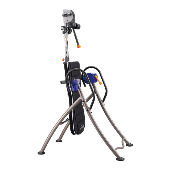
- Page 1 INVERT EASE INVERSION TABLE ITEM NO: 75303 OWNER’S MANUAL IMPORTANT: Read all instructions carefully before using this product. Retain this owner’s manual for future reference. The specifications of this product may vary from this photo and are subject to change without prior notice.
-
Page 2: Table Of Contents
TABLE OF CONTENTS WARRANTY ------------------------------------------------------------------------------- 2 IMPORTANT SAFETY INSTRUCTIONS ------------------------------------------- 3 OVERVIEW DRAWING ----------------------------------------------------------------- 5 PARTS LIST ------------------------------------------------------------------------------- 7 HARDWARE LIST ----------------------------------------------------------------------- 9 TOOLS -------------------------------------------------------------------------------------- 9 ASSEMBLY INSTRUCTIONS --------------------------------------------------------- 10 HOW TO USE ----------------------------------------------------------------------------- 16 QUICK RELEASE ANKLE LOCK ----------------------------------------------------- 18 OPERATION ------------------------------------------------------------------------------- 19 STORAGE ---------------------------------------------------------------------------------- 21 WARM UP AND COOL DOWN ROUTINE ----------------------------------------- 22... -
Page 3: Warranty
ONE YEAR LIMITED WARRANTY LifeGear Inc. warrants to the original purchaser that this product is free from defects in material and workmanship when used for the purpose intended, under the conditions that it has been installed and operated in accordance with LifeGear's Owner's Manual. LifeGear's obligation under this warranty is limited to replacing or repairing free of charge, any parts which may prove to be defective under normal home use. -
Page 4: Important Safety Instructions
IMPORTANT SAFETY INSTRUCTIONS This inversion table was designed and built for optimum safety. However, certain precautions apply whenever you operate the exercise equipment. Be sure to read the entire manual before assembling and operating this equipment. When using an appliance, basic precautions should always be followed, including the following: WARNING - To reduce the risk of injury to persons:... - Page 5 WARNING - Risk of personal injury - Do not grab the Lock Handle Plastic Bar for getting up, use the handlebar instead. WARNING - Risk of personal injury - Keep body parts, hair, loose clothing and jewelry clear of all moving parts. NOTE: Maximum user weight for this product is 160 kgs.
-
Page 6: Overview Drawing
OVERVIEW DRAWING... - Page 7 OVERVIEW DRAWING 11 62...
-
Page 8: Parts List
PARTS LIST Description Qty No. Description 001 Front Frame 1 030 Knob 002 Cup Holder 1 031 Rubber Heel Holder Cross Recessed Oval Head Bolt 003 Rear Frame 1 032 M6x30 004 Cup Holder Rotation Cap 1 033 Lock Mechanism 005 Front Heel Holder 2 034 Lock Handle Plastic Bar 006 Gear Plate... - Page 9 PARTS LIST Description Qty No. Description 059 Button 1 074 Rotor Cover 060 Handle Tip 1 075 Left Brake Pad II 061 Blocking Bush Ø28.5xØ22.5x10 2 076 Pin 062 Screw ST3.5x10 19 077 Washer Ø4.3xØ9xt0.3 Spring Washer 2 078 Lock Nut M8 Ø8.1xØ12.3x2.1mm 064 Carriage Bolt M8x60 2 079 Spring...
-
Page 10: Hardware List
HARDWARE LIST (13) Washer (14) Curve Washer (15) Lock Nut M8 Ø8.5xØ20xt1.5 Ø8.5xØ16xt2.0 (Galvanize) 6 PCS 2 PCS 4 PCS (27) Washer (38) Bolt M8x60 (43) Bolt M8x12 Ø12xØ6.5x1.0 2 PCS 2 PCS 4 PCS (46) Bolt M8x20 (51) Bolt M6x15 (76) Pin 4 PCS 4 PCS... -
Page 11: Assembly Instructions
ASSEMBLY INSTRUCTIONS Step 1 Lay the base on its side as shown. Attach the Front Foot Caps (53) to the Front Frame (1) each with one Ø12xØ6.5x1.0 Washer (27) and one M6x15 Bolt (51). Attach the Rear Foot Caps (49) to the Rear Frame (3) each with one Ø12xØ6.5x1.0 Washer (27) and one M6x15 Bolt (51). - Page 12 Correct Incorrect Step 2 Stand up the base and open fully. Make sure all Foot Caps are level. Insert the Pin (76) into Frames. Install two Caps (82) onto two M8 Lock Nuts (15). Hardware: (76) Pin (82) Cap 1 PC 2 PCS...
- Page 13 Step 3 Attach the Bed Frame (10) onto the Right Pivot Arm (12) and Left Pivot Arm (19) by using two M8 Lock Nuts (15), two M8x12 Bolts (43), two M8x20 Bolts (46) and two Ø8.5xØ20xt1.5 Washers (13). Tighten M8x12 Bolts (43) with #5 Allen Wrench provided. Tighten M8x20 Bolts (46) and M8 Lock Nuts (15) with #6 Allen Wrench and Multi Hex Tool with Phillips Screwdriver provided.
- Page 14 Step 4 Attach both Handlebars (29) onto Rear Frame (3) with four Ø8.5xØ20xt1.5 Washers (13), two Ø8.5xØ16xt2.0 Curve Washers (14), two M8 Lock Nuts (15), two Bolts (38) and two M8x20 Bolts (46). Tighten M8x20 Bolts (46) with #6 Allen Wrench provided. Tighten M8x60 Bolts (38) and M8 Lock Nuts (15) with #6 Allen Wrench and Multi Hex Tool with Phillips Screwdriver provided, attach the Caps (82) to the M8 Lock Nuts (15).
- Page 15 Step 5 Slide two Heel Holder Brackets (7) and Rubber Heel Holders (31) onto both ends of the Rear Rod (9) until the lock teeth are wedged into the slots in the Rear Rod (9), as shown in detailed drawing below. Slide Front Heel Holder (5) onto Front Rod (11).
- Page 16 Step 6 Loosen the Knob (30). Pull the Spring Knob (18) and slide the Adjustable Boom (8) in. Slide the Adjustable Boom (8) up to the desired height. Release the Spring Knob (18) and make sure it “pops” into the hole. Tighten the Knob (30) for additional safety.
-
Page 17: How To Use
HOW TO USE Set the Adjustable Boom to your height Turn the Knob counter-clockwise to loosen the Adjustable Boom. Adjustable Pull the Spring Knob as you adjust the Boom Adjustable Boom to desired height. Turn Knob clockwise to de-rattle the Adjustable Boom. - Page 18 Get to inversion Push the Lock Handle Plastic When you’re at desired angle, pull the Lock Handle Plastic Bar forward Bar to UNLOCK position. to LOCK position to lock the bed. With both hands on handles, slowly lie down. Get to vertical inversion Pull the Lock Handle Plastic Bar to LOCK position.
-
Page 19: Quick Release Ankle Lock
QUICK RELEASE ANKLE LOCK Before mounting the table, press the button on top and pull open. Pull the handle to lock your feet securely after mounting the table. When dismounting the table, press the button to release and open. If the button is too tight, pull the handle toward you first before pressing the button to release. -
Page 20: Operation
OPERATION The Handlebars For added convenience and safety, a set of Handlebars has been added to the inversion table. These Handlebars are located at the top of the Rear Frames. The Handlebars are there to help you return to the upright position from any degree of inversion. If you wish to return to the upright position, and the bed is moving too slowly, or not moving at all, simply grab the Handlebars and pull on them until you return to the upright position. - Page 21 USING THE INVERSION TABLE Start by lying fully back on the bed with your hands at your side, or resting on your thighs. Keeping your hands close to your body begin to raise your arms slowly allowing the table to rotate backward. Stop, or lower your arms to control the downward rotation of the table.
-
Page 22: Storage
STORAGE Pull out the Pin (76), and then fold the Front Frame (1) and the Rear Frame (3). Tool: Multi Hex Tool with Phillips Screwdriver When the inversion table is displayed in a store, or when it is not in use, it should be locked with the Tube Clamp (87) to prevent unsupervised use. -
Page 23: Warm Up And Cool Down Routine
WARM UP AND COOL DOWN ROUTINE The WARM-UP is an important part of any workout. The purpose of warming up is to prepare your body for exercise and to minimize injuries. Warm up for two to five minutes before aerobic exercising. It should begin every session to prepare your body for more strenuous exercise by heating up and stretching your muscles, increasing your circulation and pulse rate, and delivering more oxygen to your muscles. - Page 24 QUADRICEPS STRETCH With one hand against a wall for balance, reach behind you and pull your right foot up. Bring your heel as close to your buttocks as possible. Hold for 15 counts and repeat with left foot. INNER THIGH STRETCH Sit with the soles of your feet together and your knees pointing outward.
Need help?
Do you have a question about the 75303 and is the answer not in the manual?
Questions and answers