Table of Contents
Advertisement
Quick Links
Advertisement
Table of Contents

Related Manuals for LifeGear 30640


Summary of Contents for LifeGear 30640
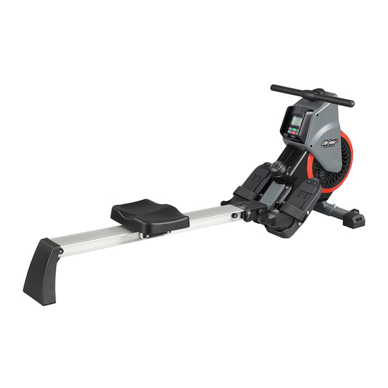
- Page 1 AIR MAGNETIC ROWER ITEM NO: 30640 OWNER’S MANUAL IMPORTANT: Read all instructions carefully before using this product. Retain this owner’s manual for future reference. The specifications of this product may vary from this photo and are subject to change without prior notice.
-
Page 2: Table Of Contents
TABLE OF CONTENTS WARRANTY -------------------------------------------------------------------------------- 2 IMPORTANT SAFETY INSTRUCTIONS ------------------------------------------- 3 PARTS LIST -------------------------------------------------------------------------------- 4 HARDWARE PACK ---------------------------------------------------------------------- 6 EXPLODED VIEW ------------------------------------------------------------------------ 7 ASSEMBLY INSTRUCTIONS --------------------------------------------------------- 8 STORAGE ---------------------------------------------------------------------------------- 14 MAINTENANCE --------------------------------------------------------------------------- 15 MOVING THE ROWER ------------------------------------------------------------------ 15 OPERATING THE COMPUTER ------------------------------------------------------ 16 ADJUSTMENTS --------------------------------------------------------------------------- 17 TROUBLESHOOTING ------------------------------------------------------------------- 19 WARM UP AND COOL DOWN ROUTINE ----------------------------------------- 20... -
Page 3: Warranty
ONE YEAR LIMITED WARRANTY LifeGear Inc. warrants to the original purchaser that this product is free from defects in material and workmanship when used for the purpose intended, under the conditions that it has been installed and operated in accordance with LifeGear's Owner's Manual. -
Page 4: Important Safety Instructions
IMPORTANT SAFETY INSTRUCTIONS Basic precautions should always be followed, including the following important safety instructions when using this equipment. Read all instructions before using this equipment. Read all instructions and follow it carefully before using this equipment. Make sure the equipment is properly assembled and tightened before use. Before exercise, in order to avoid muscle injury, warm-up exercises are recommended. -
Page 5: Parts List
PARTS LIST Description Qty No. Description 001 Right Foot Pedal 1 031 Left Cover 002 Left Foot Pedal 1 032 Right Cover 003 Plastic Fan Plate Ø316x136 1 033 Sensor Bracket 29x15x9.4 004 Rolling Wheel Ø37x32 1 034 Handlebar Ø25.4x15.Tx560 005 Rear Stabilizer 1 035 Computer Console 1 036 Wire Clip Ø1/8”... - Page 6 PARTS LIST Description Qty No. Description 061 Washer Ø10.5xØ20xT3.0 1 068 Front Stabilizer End Cap 062 Spring Washer Ø6.1xØ9.3xT1.6 6 069 Transport Wheel Ø50xØ8.5x21 Hexagon Socket Button Head Bolt 063 Adjustable Foot Pedal 2 070 M8x35 064 Pedal Strap 2 071 Lock Nut M8 Hexagon Socket Round Head 065 Seat 260x320x52 1 072...
-
Page 7: Hardware Pack
HARDWARE PACK STEP 3 STEP 5 (28) Buffer 2 PCS (50) Hexagon Socket (49) Cross Recessed Button Head Truss Head Bolt 2 PCS Bolt 4 PCS (50) Hexagon Socket (60) Washer 4 PCS Button Head Bolt 2 PCS (60) Washer 2 PCS Allen Wrench with Phillips... -
Page 8: Exploded View
EXPLODED VIEW... -
Page 9: Assembly Instructions
ASSEMBLY INSTRUCTIONS STEP 1 Position the Front Stabilizer (9) in front of the Main Frame (11) and align bolt holes. Attach the Front Stabilizer (9) onto the Main Frame (11) with two Carriage Bolts (44), two Cap Nuts (48), and two Washers (60). Tighten cap nuts with the Double Open End Wrench provided. - Page 10 50 60 60 50 STEP 2 A. Slide the Slide Tube (6) onto the Support Slide Tube (12) and align bolt holes. Attach the Slide Tube (6) onto the Support Slide Tube (12) with four Hexagon Socket Button Head Bolts (50) and four Washers (60). Tighten bolts with the Allen Wrench with Phillips Screwdriver provided.
- Page 11 NOTE: This side faces downwards. STEP 3 A. Slide the Seat (65) to the Slide Tube (6). B. Attach the Rear Stabilizer (5) to the rear end of the Slide Tube (6) with two Buffers (28), two Cross Recessed Truss Head Bolts (49), two Hexagon Socket Button Head Bolts (50) and two Washers (60).
- Page 12 STEP 4 Hold the Slide Tube (6) with one hand and use the other hand to pull out the Safety Pin (13) from the Main Frame (11) and Support Slide Tube (12). STEP 4-1 Lower the Rear Stabilizer (5) until it makes contact with the floor. Lift the Main Frame (11) and Slide Tube (6) to align the holes and insert the Safety Pin (13) into the hole on the Main Frame (11).
- Page 13 STEP 5 Insert both Foot Pedal Axles (14) onto the Main Frame (11), and insert both Right and Left Foot Pedals (1, 2) onto the Foot Pedal Axles (14). Tighten both Right and Left Foot Pedals (1, 2) in place with four Hexagon Socket Button Head Bolts (50) and four Washers (60) by using the Allen Wrench with Phillips Screwdrivers provided.
- Page 14 CLIP STEP 6 A. Lift up on the CLIP and gently pulling the Computer Console (35) out. BE CAREFUL when pulling the Computer Console (35) out. There are three wires attached to the backside. B. Using the Allen Wrench with Phillips Screwdriver to remove the screw from the Computer Console (35) to open the battery cover.
-
Page 15: Storage
STORAGE To store the Rower: Hold the Slide Tube (6) with one hand and use the other hand to pull out the Safety Pin (13) from the Main Frame (11). Lift the Slide Tube (6) up until the Main Frame (11) and Support Slide Tube (12) to align the holes and insert the Safety Pin (13) into the hole on the Main Frame (11). -
Page 16: Maintenance
MAINTENANCE The rower can be cleaned with a soft damp cloth. Do not use abrasives or solvents on plastic parts. Please wipe your perspiration off the rower after each use. Be careful not to get excessive moisture on the computer display panel as this might cause an electrical hazard or it may cause the electronics to fail. -
Page 17: Operating The Computer
OPERATING THE COMPUTER USING THE COMPUTER CONSOLE Power On: The computer console will turn on when the user starts rowing or presses a button on the computer console. Power Off: The computer console will automatically turn off after 20 minutes of inactivity. Reset: Press and hold the STOP button for 3 seconds to reset the computer console. -
Page 18: Adjustments
SPLIT: Will display the average time it takes to travel 500 meters based on the current workout pace. WATTS: Will display the current workout effort in the form of Watts. The Watts value is dependent on the length of the pull, the pace of the workout, and the resistance level. - Page 19 Adjustable Leveler Adjusting the Adjustable Leveler Turn the adjustable leveler on the front stabilizer as needed to level the rower. Adjusting the Adjustable Foot Pedal First pull the adjustable foot pedal up and then slide the adjustable foot pedal up or down direction to the suitable position.
-
Page 20: Troubleshooting
TROUBLESHOOTING PROBLEM: The rower wobbles when in use. SOLUTION: Turn the adjustable level on the front stabilizer as needed to level the rower. PROBLEM: There is no display on the computer console. SOLUTION: Remove the computer console and verify the wires that come from the computer console are properly connected to the wires that come from the main frame. -
Page 21: Warm Up And Cool Down Routine
WARM UP AND COOL DOWN ROUTINE The WARM-UP is an important part of any workout. The purpose of warming up is to prepare your body for exercise and to minimize injuries. Warm up for two to five minutes before aerobic exercising. Warming up should prepare your body for more strenuous exercise by heating up and stretching your muscles, increasing your circulation and pulse rate, and delivering more oxygen to your muscles. - Page 22 QUADRICEPS STRETCH With one hand against a wall for balance, reach behind you and pull your right foot up. Bring your heel as close to your buttocks as possible. Hold for 15 counts and repeat with left foot. INNER THIGH STRETCH Sit with the soles of your feet together and your knees pointing outward.
Need help?
Do you have a question about the 30640 and is the answer not in the manual?
Questions and answers