Table of Contents
Advertisement
Quick Links
Advertisement
Table of Contents

Related Manuals for LifeGear 63100


Summary of Contents for LifeGear 63100
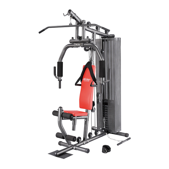
- Page 1 LifeGear G1 /HOME GYM ITEM NO.: 63100 OWNER’S MANUAL IMPORTANT: Read all instructions carefully before using this product. Retain this owner’s manual for future reference. The specifications of this product may vary from this photo, subject to change without notice.
-
Page 2: Table Of Contents
TABLE OF CONTENTS WARRANTY ------------------------------------------------------------------------------- 2 IMPORTANT SAFETY INSTRUCTIONS ------------------------------------------- 3 PARTS NUMBERS AND ILLUSTRATIONS --------------------------------------- 4 PARTS LIST ------------------------------------------------------------------------------- 6 MAINTENANCE -------------------------------------------------------------------------- 7 HARDWARE PACKING LIST --------------------------------------------------------- 8 OVERVIEW DRAWING ----------------------------------------------------------------- 11 ASSEMBLY INSTRUCTIONS --------------------------------------------------------- 12 CABLE LOOP DIAGRAM -------------------------------------------------------------- 25 PULLEYS AND LAT BAR CABLE INSTALLATION ------------------------------ 26 PULLEYS AND BUTTERFLY ARM CABLE INSTALLATION ------------------ 31 PULLEYS AND ABDOMINAL CABLE INSTALLATION ------------------------- 34... -
Page 3: Warranty
ONE YEAR LIMITED WARRANTY LifeGear Inc. warrants to the original purchaser that this product is free from defects in material and workmanship when used for the purpose intended, under the conditions that it has been installed and operated in accordance with LifeGear's Owner's Manual. LifeGear's obligation under this warranty is limited to replacing or repairing free of charge, any parts which may prove to be defective under normal home use. -
Page 4: Important Safety Instructions
IMPORTANT SAFETY INSTRUCTIONS Basic precautions should always be followed, including the following safety instructions when using this home gym. Read all instructions before using this home gym. Read all the instructions in this manual and do warm up exercises before using this home gym. -
Page 5: Parts Numbers And Illustrations
PARTS NUMBERS AND ILLUSTRATIONS... - Page 6 PARTS NUMBERS AND ILLUSTRATIONS...
-
Page 7: Parts List
PARTS LIST Description Qty No. Description 001 Main Base Tube 1 033 Leg Extension Cable 002 Main Support Tube 1 034 Abdominal Strap 003 Top Frame 1 035 Ankle Strap 004 Side Pulley Bracket 1 036 Top Weight Stack 005 Support Tube 1 037 Weight Stack 006 Weight Sliding Rod 2 038 Plastic Bushing... -
Page 8: Maintenance
PARTS LIST Description Qty No. Description 065 Ø19 Steel Bushing 2 080 M8x20 Hex Bolt 066 Ø16 Steel Bushing 4 081 M8x45 Hex Bolt 067 M8 Nylon Lock Nut 1 082 M8x80 Hex Bolt 068 M10 Nylon Lock Nut 34 083 M10x25 Hex Bolt 069 M12 Nylon Lock Nut 2 084 M10x45 Hex Bolt 070 M16 Nylon Lock Nut... -
Page 9: Hardware Packing List
HARDWARE PACKING LIST Hardware Bag (17) Lock Bar (39) Pin (40) Big Washer (42) L-Shaped Pin 1 PC 1 PC 1 PC 1 PC (62) Ring Pin (63) Hook (64) Coil Chain (200) (67) Nylon Lock 1 PC 6 PCS 2 PCS Nut M8 1 PC... - Page 10 (91) M8x12 Hex Bolt (94) Ø8 Big Washer 16 PCS 16 PCS Plastic Parts (38) Plastic Bushing (43) Rubber Bumper (56) Lock Bar Knob 1 PC 2 PCS 1 PC (57) Round Knob (61) Flange Cover (92) Hex Nut Cap M12 1 PC 4 PCS 2 PCS...
- Page 11 Cables (30) Lat Bar Cable (31) Butterfly Arm Cable 1 PC 1 PC (32) Abdominal Cable (33) Leg Extension Cable 1 PC 1 PC Accessories (34) Abdominal Strap (35) Ankle Strap 1 PC 1 PC Weight Stack Pack (36) Top Weight Stack (37) Weight Stack (Approximately 4.5 kgs/10 lbs) (Approximately 5.7 kgs/12.5 lbs)
-
Page 12: Overview Drawing
OVERVIEW DRAWING... -
Page 13: Assembly Instructions
ASSEMBLY INSTRUCTIONS NOTE: It is recommended that you always use the aid of a second person when assembling the home gym. Tool: 2 Wrenches (19-17) Step 1 Attach the Front Stabilizer (23) onto the Main Base Tube (1) and Foot Frame (14) with two M10 Nylon Lock Nuts (68), two M10x80 Hex Bolts (86), and four Ø10 Curve Washers (77). - Page 14 Tool: 2 Wrenches (19-17) Step 2 Attach the Main Support Tube (2) onto the Main Base Tube (1) with two M10 Nylon Lock Nuts (68), two M10x80 Hex Bolts (86), and four Ø10 Flat Washers (73). Tighten bolts and nuts with two Wrenches provided. Attach the Side Pulley Bracket (4) onto the tube of the Main Base Tube (1) with one M12 Nylon Lock Nut (69).
- Page 15 Tool: hole INCORRECT CORRECT 1 Allen Wrench (6mm) Step 3 Slide two Rubber Bumpers (43) onto the Weight Stack Sliding Rods (6). Then insert two Stack Sliding Rods (60) into the holes of the Bottom Cover Support (88) and Rear Stabilizer (24).
- Page 16 CORRECT INCORRECT Step 4 Install each Weight Stack (37) onto the Weight Stack Sliding Rods (6). NOTE: Ensure that each weight stack’s selector pin slot faces downward. Slide the Plastic Bushing (38) onto the Guide Rod (41) and align pin hole. Secure the Plastic Bushing (38) onto the Guide Rod (41) by inserting the Pin (39) through into the holes of the Guide Rod (41) and Plastic Bushing (38).
- Page 17 Tool: 2 Wrenches (19-17) Step 5 Insert each Weight Stack Sliding Rod (6) into the corresponding hole in the Top Frame (3). Secure Weight Stack Sliding Rods (6) in the Top Frame (3) using two M10x25 Hex Bolts (83) and two Ø10 Curve Washers (77). Tighten bolts with the Wrench provided. Attach the Top Frame (3) onto the Main Support Tube (2) with one Curve Plate I (25), two M10x80 Hex Bolts (86), two M10 Nylon Lock Nuts (68), and four Ø10 Curve Washers (77).
- Page 18 Tool: 77 68 2 Wrenches (19-17) Step 6 Attach the Lock Bar (17) onto the Main Support Tube (4) with two M10x80 Hex Bolts (86), two M10 Nylon Lock Nuts (68), and four Ø10 Curve Washers (77). Tighten bolts and nuts with two Wrenches provided.
- Page 19 Tool: 77 68 86 77 2 Wrenches (19-17) Step 7 Attach the Seat Support Frame (7) onto the Main Support Tube (2) with one Curve Plate I (25), two M10x80 Hex Bolts (86), two M10 Nylon Lock Nuts (68), and four Ø10 Curve Washers (77).
- Page 20 Tool: 2 Wrenches (19-17) Step 8 Attach the Leg Extension Tube (8) onto the clevis of the Seat Support Frame (7) with one M12x85 Hex Bolt (87), one M12 Nylon Lock Nut (69), and two Ø12 Flat Washers (74). Tighten bolt and nut with two Wrenches provided. Install two M12 Hex Nut Caps (92) onto the M12x85 Hex Bolt (87) and M12 Nylon Lock Nut (69).
- Page 21 Tool: 1 Wrench (14-10) Step 9 Attach the Backrest (28) onto the Main Support Tube (2) with two Ø8 Curve Washers (76) and two M8x80 Hex Bolts (82). Tighten bolts with the Wrench provided. Attach the Seat Pad (29) onto the Seat Frame (9) with four Ø6 Flat Washers (71) and four M6x20 Hex Bolts (79).
- Page 22 Step 10 Slide the Foam Roll Tube (22) through the round hole on the clevis of the Seat Support Frame (7). Slide two Ø80x160 Foam Rollers (47) onto both ends of the Foam Roll Tube (22). Slide the Foam Roll Tube (22) through the round hole on the Leg Extension Tube (8). Slide two Ø80x160 Foam Rollers (47) onto both ends of the Foam Roll Tube (22).
- Page 23 Tool: 67 72 2 Wrenches (14-10) Step 11 Attach the Support Frame for Butterfly Arm (11) onto the Top Frame (3) with one Shaft (21) and two M8x20 Hex Bolts (80). Tighten bolt with the Wrench provided. Attach the Lock Bar (17) onto the clevis of the Support Tube (5) with one M8x45 Hex Bolt (81), one M8 Nylon Lock Nut (67), and two Ø8 Flat Washers (72).
- Page 24 Tool: 1 Wrench (19-24) Step 12 Attach the Right Butterfly Arm (12) onto the Support Frame for Butterfly Arm (11) with one Ø16 Flat Washer (75 )and one M16 Nylon Lock Nut (70). Tighten nut with the Wrench provided. Install one M16 Hex Nut Caps (93) onto the M16 Nylon Lock Nut (70). Use the same procedure to install the Left Butterfly Arm (13) onto the Support Frame for Butterfly Arm (11).
- Page 25 Tool: 77 83 1 Wrench (19-17) Step 13 Slide the Ø90x245 Foam Roll (48) onto the Right Butterfly Arm (12). Attach the L Handle (10) onto the Right Butterfly Arm (12) with two Ø10 Curve Washers (77) and two M10x25 Hex Bolts (83). Tighten bolts with the Wrench provided. Use the same procedure to install the other Ø90x245 Foam Roll (48) and L Handle (10) onto the Left Butterfly Arm (13).
-
Page 26: Cable Loop Diagram
CABLE LOOP DIAGRAM 61 73 68... -
Page 27: Pulleys And Lat Bar Cable Installation
PULLEYS AND LAT BAR CABLE INSTALLATION 61 73 68 Lat Bar Cable Tool: 2 Wrenches (19-17) Step 1 Insert the Lat Bar Cable (30) around the Pulley (60) with the ball end of the cable at the front of the Pulley (60). Then attach the Pulley (60) onto the Top Frame (3) with one M10x80 Hex Bolt (86), one M10 Nylon Lock Nut (68), two Ø10 Flat Washers (73), and two Flange Covers (61). - Page 28 Tool: 2 Wrenches (19-17) Step 2 Pull the Lat Bar Cable (30) towards to the second Pulley (60) and draw it under the Pulley (60). Then attach the Pulley (60) onto the Top Frame (3) with one M10x45 Hex Bolt (84), one M10 Nylon Lock Nut (68), and two Ø10 Flat Washers (73).
- Page 29 Tool: 2 Wrenches (19-17) Step 3 Pull the Lat Bar Cable (30) downwards. Draw the Lat Bar Cable (30) around the Pulley (60). Then attach the Pulley (60) onto the Double Floating Pulley Bracket (19) with one M10x45 Hex Bolt (84), one M10 Nylon Lock Nut (68), and two Ø10 Flat Washers (73). Tighten bolt and nut with two Wrenches provided.
- Page 30 Tool: 2 Wrenches (19-17) Step 4 Pull the Lat Bar Cable (30) upwards to the Pulley (60) and draw it around the Pulley (60). Then attach the Pulley (60) onto the Top Frame (3) with one M10x45 Hex Bolt (84), one M10 Nylon Lock Nut (68), and two Ø10 Flat Washers (73).
- Page 31 Step 5 Pull the Lat Bar Cable (30) downwards to the Guide Rod (41). Thread the bolt at the end of the Lat Bar Cable (30) into the opening on top of the Guide Rod (41) to secure the cable. PLEASE REFER TO THE “CABLE LOOP DIAGRAM”...
-
Page 32: Pulleys And Butterfly Arm Cable Installation
PULLEYS AND BUTTERFLY ARM CABLE INSTALLATION Butterfly Arm Cable Tool: 2 Wrenches (19-17) Step 1 Attach one end of the Butterfly Arm Cable (31) onto the Left Butterfly Arm (13) with one M10x25 Hex Bolt (83), one M10 Nylon Lock Nut (68), and two Ø10 Flat Washers (73). Tighten bolt and nut with two Wrenches provided. - Page 33 Tool: 2 Wrenches (19-17) Step 2 Attach the Pulley Bracket (20) onto the left clevis of the Main Support Tube (2) with one M10x65 Hex Bolt (85), one M10 Nylon Lock Nut (68), and two Ø10 Flat Washers (73). Tighten bolt and nut with two Wrenches provided. Insert the other end of the Butterfly Arm Cable (31) around the Pulley (60).
- Page 34 Tool: 2 Wrenches (19-17) Step 3 Pull the Butterfly Arm Cable (31) downwards to the Crossed Double Floating Pulley Bracket (18). Draw the Butterfly Arm Cable (31) around the Pulley (60) on the Crossed Double Floating Pulley Bracket (18). Then attach the Pulley (60) onto the Crossed Double Floating Pulley Bracket (18) with one M10x45 Hex Bolt (84), one M10 Nylon Lock Nut (68), and two Ø10 Flat Washers (73).
-
Page 35: Pulleys And Abdominal Cable Installation
PULLEYS AND ABDOMINAL CABLE INSTALLATION Abdominal Cable Tool: 2 Wrenches (19-17) Step 1 Insert the Abdominal Cable (32) around the Pulley (60) with the ball end of the cable at the front of the Pulley (60). Then attach the Pulley (60) onto the Main Support Tube (2) with one M10x80 Hex Bolt (86), one M10 Nylon Lock Nut (68), two Ø10 Flat Washers (73), and two Flange Covers (61). - Page 36 Tool: 2 Wrenches (19-17) Step 2 Pull the Abdominal Cable (32) downwards. Draw the Abdominal Cable (32) around the Pulley (60). Then attach the Pulley (60) onto two Pulley Plates (27) with one M10x45 Hex Bolt (84), one M10 Nylon Lock Nut (68), and two Ø10 Flat Washers (73). Tighten bolt and nuts with two Wrenches provided.
- Page 37 Tool: 2 Wrenches (19-17) Step 3 Pull the Abdominal Cable (32) upwards. Draw the Abdominal Cable (32) around the Pulley (60). Then attach the Pulley (60) onto the Double Floating Pulley Bracket (19) with one M10x45 Hex Bolt (84), one M10 Nylon Lock Nut (68), and two Ø10 Flat Washers (73). Tighten bolt and nut with two Wrenches provided.
- Page 38 Step 4 Pull the Abdominal Cable (32) downwards to connect the Hook (63) to the end of the Abdominal Cable (32) and Coil Chain (64). Connect the other Hook (63) to the Coil Chain (64) and Main Base Tube (1). PLEASE REFER TO THE “CABLE LOOP DIAGRAM”...
- Page 39 Step 5 Connect the Hook (63) to the ball stopper end of the Abdominal Cable (32) and Abdominal Strap (34). PLEASE REFER TO THE “CABLE LOOP DIAGRAM” SECTION ON PAGE Hardware: (63) Hook 1 PC Accessory: (34) Abdominal Strap 1 PC...
-
Page 40: Pulleys And Leg Extension Cable Installation
PULLEYS AND LEG EXTENSION CABLE INSTALLATION Leg Extension Cable Tool: 2 Wrenches (19-17) Step 1 Insert the Leg Extension Cable (33) around the Pulley (60) with the ball end of the cable at the front of the Pulley (60). Then attach the Pulley (60) onto the Side Pulley Bracket (4) with one M10x45 Hex Bolt (84), one M10 Nylon Lock Nut (68), and two Ø10 Flat Washers (73). - Page 41 Tool: 2 Wrenches (19-17) Step 2 Pull the Leg Extension Cable (33) upwards. Draw the Leg Extension Cable (33) around the Pulley (60). Then attach the Pulley (60) onto two Pulley Plates (27) with one M10x45 Hex Bolt (84), one M10 Nylon Lock Nut (68), and two Ø10 Flat Washers (73). Tighten bolt and nut with two Wrenches provided.
- Page 42 Tool: 2 Wrenches (19-17) Step 3 Pull the Leg Extension Cable (33) downwards. Draw the Leg Extension Cable (33) around the Pulley (60). Then attach the Pulley (60) onto the Main Base Tube (1) with one M10x45 Hex Bolt (84), one M10 Nylon Lock Nut (68), and two Ø10 Flat Washers (73). Tighten bolt and nut with two Wrenches provided.
- Page 43 Tool: 2 Wrenches (19-17) Step 4 Pull the Leg Extension Cable (33) upwards to the Crossed Double Floating Pulley Bracket (18). Draw the Leg Extension Cable (33) around the Pulley (60) on the Crossed Double Floating Pulley Bracket (18). Then attach the Pulley (60) onto the Crossed Double Floating Pulley Bracket (18) with one M10x45 Hex Bolt (84), one M10 Nylon Lock Nut (68), and two Ø10 Flat Washers (73).
- Page 44 Tool: 2 Wrenches (19-17) Step 5 Pull the Leg Extension Cable (33) downwards. Draw the Leg Extension Cable (33) around the Pulley (60). Then attach the Pulley (60) onto the Main Base Tube (1) with one M10x45 Hex Bolt (84), one M10 Nylon Lock Nut (68), and two Ø10 Flat Washers (73). Tighten bolt and nut with two Wrenches provided.
- Page 45 Tool: 2 Wrenches (19-17) Step 6 Pull the Leg Extension Cable (33) towards. Draw the Leg Extension Cable (33) around the Pulley (60). Then attach the Pulley (60) onto the Main Base Tube (1) with one M10x45 Hex Bolt (84), one M10 Nylon Lock Nut (68), and two Ø10 Flat Washers (73). Tighten bolt and nut with two Wrenches provided.
- Page 46 Tool: 2 Wrenches (19-17) Step 7 Pull the Leg Extension Cable (33) upwards to the Leg Extension Tube (8). Then attach the end of the Leg Extension Cable (33) onto the Leg Extension Tube (8) with one M10x25 Hex Bolt (83), one M10 Nylon Lock Nut (68), and two Ø10 Flat Washers (73). Tighten bolt and nut with two Wrenches provided.
- Page 47 Step 8 Connect the Hook (63) to the ball stopper end of the Leg Extension Cable (33) and Coil Chain (64). Connect the other Hook (63) to the Coil Chain (64) and Low Row Bar (16) or Ankle Strap (35). PLEASE REFER TO THE “CABLE LOOP DIAGRAM”...
-
Page 48: Weight Stack Cover Installation
WEIGHT STACK COVER INSTALLATION Tool: 1 Wrench (14-10) Attach four Weight Stack Covers (90) onto the Bottom Cover Support (88) and Top Cover Support (89) with two M8x20 Hex Bolts (80), sixteen M8x12 Hex Bolts (91), and sixteen Ø8 Big Washers (72). Tighten bolts with the Wrench provided. Hardware: (91) M8x12 Hex Bolt (80) M8x20 Hex Bolt... -
Page 49: Warm Up And Cool Down Routine
WARM UP AND COOL DOWN ROUTINE The WARM-UP is an important part of any workout. The purpose of warming up is to prepare your body for exercise and to minimize injuries. Warm up for two to five minutes before aerobic exercising. It should begin every session to prepare your body for more strenuous exercise by heating up and stretching your muscles, increasing your circulation and pulse rate, and delivering more oxygen to your muscles. - Page 50 QUADRICEPS STRETCH With one hand against a wall for balance, reach behind you and pull your right foot up. Bring your heel as close to your buttocks as possible. Hold for 15 counts and repeat with left foot. INNER THIGH STRETCH Sit with the soles of your feet together and your knees pointing outward.
Need help?
Do you have a question about the 63100 and is the answer not in the manual?
Questions and answers